element14 Community
element14 Community
    Register Log In
  • Site
  • Search
  • Log In Register
  • Community Hub
    Community Hub
    • What's New on element14
    • Feedback and Support
    • Benefits of Membership
    • Personal Blogs
    • Members Area
    • Achievement Levels
  • Learn
    Learn
    • Ask an Expert
    • eBooks
    • element14 presents
    • Learning Center
    • Tech Spotlight
    • STEM Academy
    • Webinars, Training and Events
    • Learning Groups
  • Technologies
    Technologies
    • 3D Printing
    • FPGA
    • Industrial Automation
    • Internet of Things
    • Power & Energy
    • Sensors
    • Technology Groups
  • Challenges & Projects
    Challenges & Projects
    • Design Challenges
    • element14 presents Projects
    • Project14
    • Arduino Projects
    • Raspberry Pi Projects
    • Project Groups
  • Products
    Products
    • Arduino
    • Avnet Boards Community
    • Dev Tools
    • Manufacturers
    • Multicomp Pro
    • Product Groups
    • Raspberry Pi
    • RoadTests & Reviews
  • About Us
  • Store
    Store
    • Visit Your Store
    • Choose another store...
      • Europe
      •  Austria (German)
      •  Belgium (Dutch, French)
      •  Bulgaria (Bulgarian)
      •  Czech Republic (Czech)
      •  Denmark (Danish)
      •  Estonia (Estonian)
      •  Finland (Finnish)
      •  France (French)
      •  Germany (German)
      •  Hungary (Hungarian)
      •  Ireland
      •  Israel
      •  Italy (Italian)
      •  Latvia (Latvian)
      •  
      •  Lithuania (Lithuanian)
      •  Netherlands (Dutch)
      •  Norway (Norwegian)
      •  Poland (Polish)
      •  Portugal (Portuguese)
      •  Romania (Romanian)
      •  Russia (Russian)
      •  Slovakia (Slovak)
      •  Slovenia (Slovenian)
      •  Spain (Spanish)
      •  Sweden (Swedish)
      •  Switzerland(German, French)
      •  Turkey (Turkish)
      •  United Kingdom
      • Asia Pacific
      •  Australia
      •  China
      •  Hong Kong
      •  India
      •  Korea (Korean)
      •  Malaysia
      •  New Zealand
      •  Philippines
      •  Singapore
      •  Taiwan
      •  Thailand (Thai)
      • Americas
      •  Brazil (Portuguese)
      •  Canada
      •  Mexico (Spanish)
      •  United States
      Can't find the country/region you're looking for? Visit our export site or find a local distributor.
  • Translate
  • Profile
  • Settings
Experimenting with Flyback Transformers
  • Challenges & Projects
  • Design Challenges
  • Experimenting with Flyback Transformers
  • More
  • Cancel
Experimenting with Flyback Transformers
Blog Blog 2: Switching MOSFET's at +100kHz frequencies in high voltage environments - it's a precursor to getting Flyback Transformers to work properly.
  • Blog
  • Forum
  • Documents
  • Polls
  • Files
  • Members
  • Mentions
  • Sub-Groups
  • Tags
  • More
  • Cancel
  • New
Join Experimenting with Flyback Transformers to participate - click to join for free!
  • Share
  • More
  • Cancel
Group Actions
  • Group RSS
  • More
  • Cancel
Engagement
  • Author Author: BigG
  • Date Created: 20 Jan 2024 10:44 PM Date Created
  • Views 2208 views
  • Likes 9 likes
  • Comments 5 comments
  • pwm
  • EXPERIMENTING WITH FLYBACK TRANSFORMERS
  • p-channel MOSFET
  • bourns
Related
Recommended

Blog 2: Switching MOSFET's at +100kHz frequencies in high voltage environments - it's a precursor to getting Flyback Transformers to work properly.

BigG
BigG
20 Jan 2024
Blog 2: Switching MOSFET's at +100kHz frequencies in high voltage environments - it's a precursor to getting Flyback Transformers to work properly.

Introduction

Intentional instability. According to Wikipedia, this is a highly sought after feature in fighter aircraft design. I think, based on my experiments so far, I could say the same for flyback transformers!

image


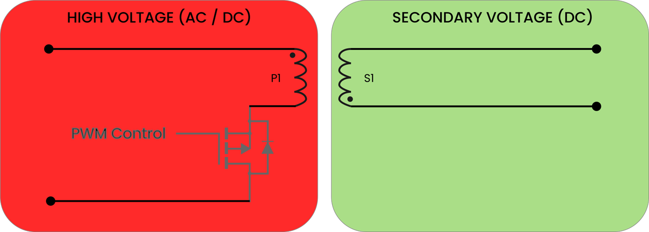
As with many other flyback transformers on the market, the ones we were provided with all typically require switching speeds in the micro to nano second range. This is not trivial and requires either a fast enough clock signal on a microcontroller together with some low-level PWM clock timer code or a dedicated PWM component that can be suitably powered within the high voltage environment.

So in this blog, I am focusing on the MOSFET to learn more about how well they can switch on and off at these high frequencies because, as they say, rubbish in equates to rubbish out.

Generating +100kHz PWM signals

I like to keep things simple. So I tend to start testing things out using Arduino code. This way I don’t have to buy additional components, if I don’t really need them.

However, so as not to leave a stone unturned, I did do a quick search for some possible PWM components. I found two examples of dedicated PWM components. Both were from Texas Instruments. The first was the TL3844BP PWM controller, which switches at up to 500kHz with a 50% duty cycle, and the other was the TL494, which provides a max PWM frequency of 300kHz.

To start me off on the microcontroller route, I thought to check out the Arduino documentation, which provides a handy tutorial on how to generate PWM signals.

https://docs.arduino.cc/learn/microcontrollers/analog-output/

In this tutorial, it shows that the “AnalogWrite()” function is used to generate a steady rectangular wave at a specified duty cycle. Neat.

However, before getting too excited by the simplicity of it all, it always pays to check the details. For this I went to the specific reference page for the AnalogWrite function. Here it provides a table with all the maximum PWM frequencies possible for all the different Arduino boards.

Basically, the Arduino AnalogWrite function is not up to my task as you cannot even get 1kHz using this function with most boards.

So another method was required, if sticking with Arduino.

Well, Arduino has already thought of it, and there is another handy documentation page titled “Secrets of Arduino PWM” on their website, which demonstrates how to achieve higher PWM frequencies. However, the tips offered are only meant for ATmega328 or the older ATmega168 chipsets.

I was not going to give up that easily with my favourite prototyping platform. I decided to stick with the Arduino IDE but went with a Raspberry Pi Pico instead as I could then test out the PICO SDK PWM example using the RP2040 PIO functionality. To do this, I simply took the raw PIO code from the existing Pico Examples written in C code (as shown here):

;
; Copyright (c) 2020 Raspberry Pi (Trading) Ltd.
;
; SPDX-License-Identifier: BSD-3-Clause
;

; Side-set pin 0 is used for PWM output

.program pwm
.side_set 1 opt

    pull noblock    side 0 ; Pull from FIFO to OSR if available, else copy X to OSR.
    mov x, osr             ; Copy most-recently-pulled value back to scratch X
    mov y, isr             ; ISR contains PWM period. Y used as counter.
countloop:
    jmp x!=y noset         ; Set pin high if X == Y, keep the two paths length matched
    jmp skip        side 1
noset:
    nop                    ; Single dummy cycle to keep the two paths the same length
skip:
    jmp y-- countloop      ; Loop until Y hits 0, then pull a fresh PWM value from FIFO

% c-sdk {
static inline void pwm_program_init(PIO pio, uint sm, uint offset, uint pin) {
   pio_gpio_init(pio, pin);
   pio_sm_set_consecutive_pindirs(pio, sm, pin, 1, true);
   pio_sm_config c = pwm_program_get_default_config(offset);
   sm_config_set_sideset_pins(&c, pin);
   pio_sm_init(pio, sm, offset, &c);
}
%}

I then popped this code in the online picoasm utility tool offered by Wokwi to generate my header file.

// -------------------------------------------------- //
// This file is autogenerated by pioasm; do not edit! //
// -------------------------------------------------- //

#pragma once

#if !PICO_NO_HARDWARE
#include "hardware/pio.h"
#endif

// --- //
// pwm //
// --- //

#define pwm_wrap_target 0
#define pwm_wrap 6

static const uint16_t pwm_program_instructions[] = {
            //     .wrap_target
    0x9080, //  0: pull   noblock         side 0     
    0xa027, //  1: mov    x, osr                     
    0xa046, //  2: mov    y, isr                     
    0x00a5, //  3: jmp    x != y, 5                  
    0x1806, //  4: jmp    6               side 1     
    0xa042, //  5: nop                               
    0x0083, //  6: jmp    y--, 3                     
            //     .wrap
};

#if !PICO_NO_HARDWARE
static const struct pio_program pwm_program = {
    .instructions = pwm_program_instructions,
    .length = 7,
    .origin = -1,
};

static inline pio_sm_config pwm_program_get_default_config(uint offset) {
    pio_sm_config c = pio_get_default_sm_config();
    sm_config_set_wrap(&c, offset + pwm_wrap_target, offset + pwm_wrap);
    sm_config_set_sideset(&c, 2, true, false);
    return c;
}

static inline void pwm_program_init(PIO pio, uint sm, uint offset, uint pin) {
   pio_gpio_init(pio, pin);
   pio_sm_set_consecutive_pindirs(pio, sm, pin, 1, true);
   pio_sm_config c = pwm_program_get_default_config(offset);
   sm_config_set_sideset_pins(&c, pin);
   pio_sm_init(pio, sm, offset, &c);
}

#endif

And then based on the Pico SDK example, I came up with some very very simple Arduino code to generate my PWM signals:

#include "hardware/clocks.h"
#include "hardware/pio.h"
#include "pwm_pio.pio.h"

// GPIO for PIO generated PWM output:
const uint PWM_PIN = 10;

// (1u << 16) is 65,536 or 256 * 256 etc.
// 20kHz = 256 * 8 = 2048
// 40kHz = 1024
// 81kHz = 512
// 120kHz = 344
// 162kHz = 256

const uint16_t FREQ = (344);


// Choose PIO instance (0 or 1)
PIO pio = pio0;
uint sm = -1;
uint offset = -1;


void setup() {

  Serial.begin(115200);
  //while (!Serial) continue;
  
  // Get first free state machine in PIO 0
  sm = pio_claim_unused_sm(pio, true);

  // Add PIO program to PIO instruction memory. SDK will find location and
  // return with the memory offset of the program.
  offset = pio_add_program(pio, &pwm_program);
  Serial.println("Loaded PIO script at offset " + String(offset,HEX));

  pwm_program_init(pio, sm, offset, PWM_PIN);
  pio_pwm_set_period(pio, sm, FREQ - 1);  

  Serial.println("PIO PWM Enabled");
  Serial.println("Setting PWM Duty Cycle to 50%");
  pio_pwm_set_level(pio, sm, FREQ*0.5);

}

void loop() {

}

// Write `period` to the input shift register
void pio_pwm_set_period(PIO pio, uint sm, uint32_t period) {
    pio_sm_set_enabled(pio, sm, false);
    pio_sm_put_blocking(pio, sm, period);
    pio_sm_exec(pio, sm, pio_encode_pull(false, false));
    pio_sm_exec(pio, sm, pio_encode_out(pio_isr, 32));
    pio_sm_set_enabled(pio, sm, true);
}

// Write `level` to TX FIFO. State machine will copy this into X.
void pio_pwm_set_level(PIO pio, uint sm, uint32_t level) {
    pio_sm_put_blocking(pio, sm, level);
}

This code can generate a PWM frequency of your choice and you can also set the duty cycle using these two functions pio_pwm_set_period() and pio_pwm_set_level().

And here is a 162kHz PWM frequency with a 50% duty cycle seen on the assigned GPIO:
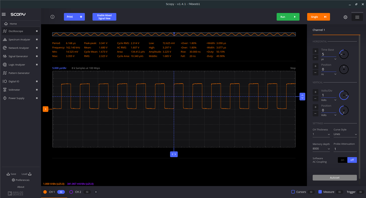
image

Success!

I now had a simple means of generating high speed PWM signals in a normal low voltage safe environment.

I could now move onto the next part of testing out some MOSFET’s using this PWM signal, as a switch, to see what happens to the voltage levels across the source of the MOSFET and ground.

Switching MOSFETs using +100kHz PWM signals

I started with the first one I could find on my desk. It was a n-channel MOSFET from ONSemi (NTD5867NL) nicely packaged as a breakout board from Freetronics, which also included the necessary resistors.

image

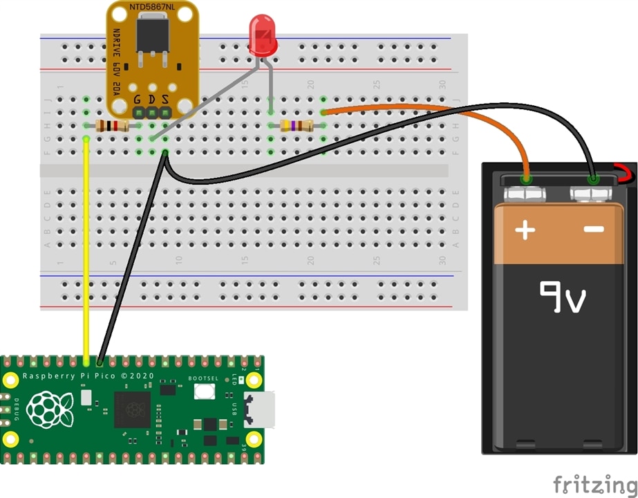
For my MOSFET testing, I started with a low PWM frequency and then increased the frequency until I reached my target frequency of 120kHz. I was keen to see at what frequency the square wave changed shape. In all cases I kept the duty cycle at 50%.

{gallery:autoplay=false}N-Channel MOSFET

image

image

image


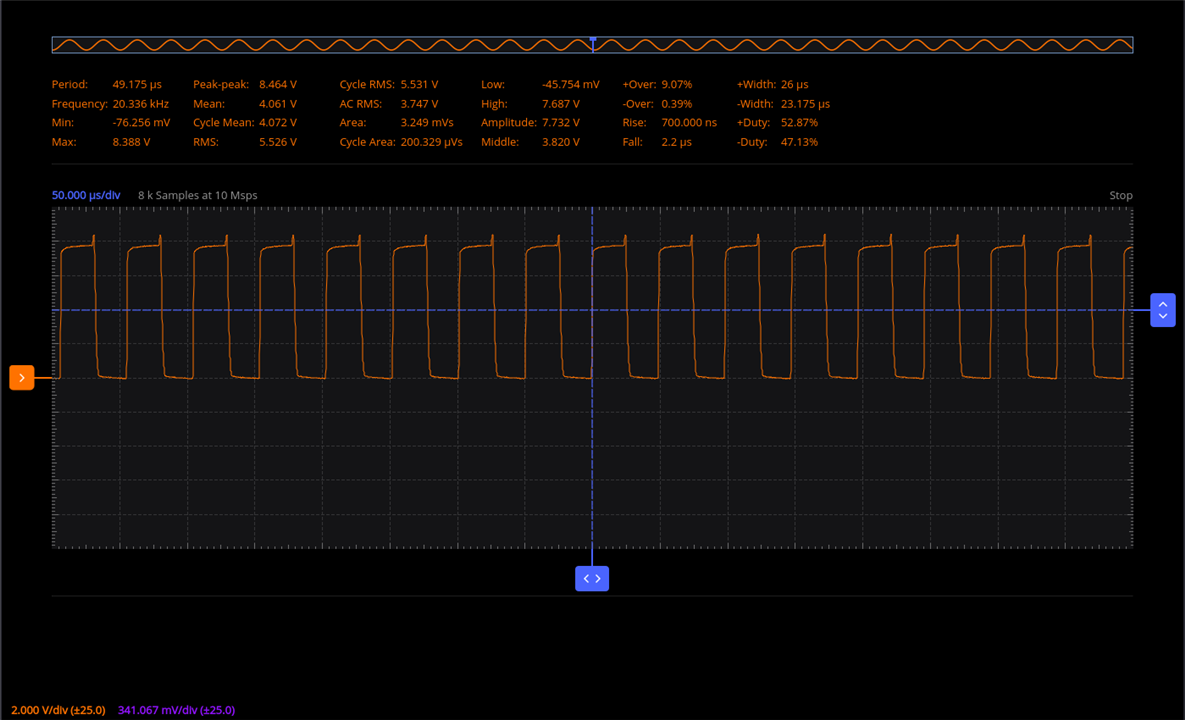
So, based on my tests (as shown) I was able to reach 80kHz PWM before the NTD5867NL n-channel MOSFET could no longer replicate the clean square wave.

Does this match the specification? I’ll leave it up to you to decide.

image

Experimenting with a P-Channel MOSFET

I had forgotten to order in some through-hole P-Channel MOSFET’s so I was left soldering on wires to a SOT-23 SMD component. Thankfully, I had a small enough soldering tip to make short work of this little hack.

image

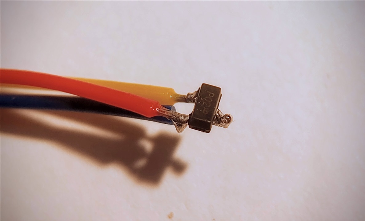
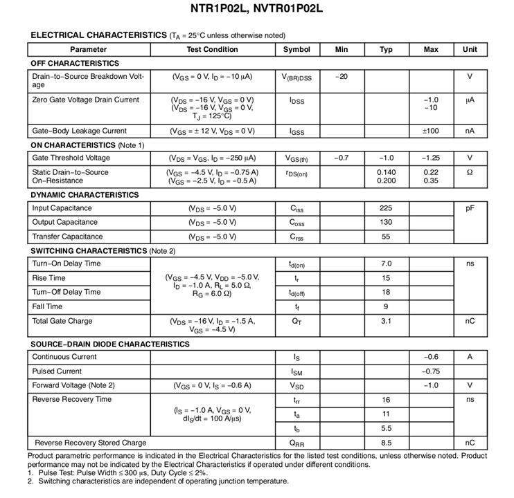
The tiny MOSFET in question was the NTR1P02LT1-D from Onsemi. According to the datasheet, typical applications for these miniature SMD are DC−DC converters and power management in portable and battery−powered products.

image

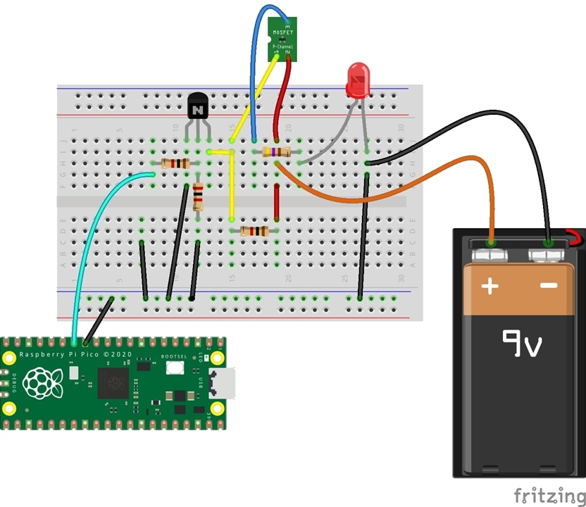
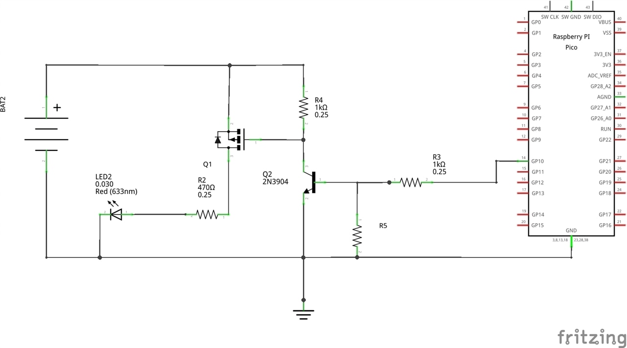
The test circuit a fairly standard p-channel switch circuit which included an additional transistor to switch the MOSFET with a 3V3 microcontroller:

{gallery:autoplay=false}P-channel Circuit

image

image

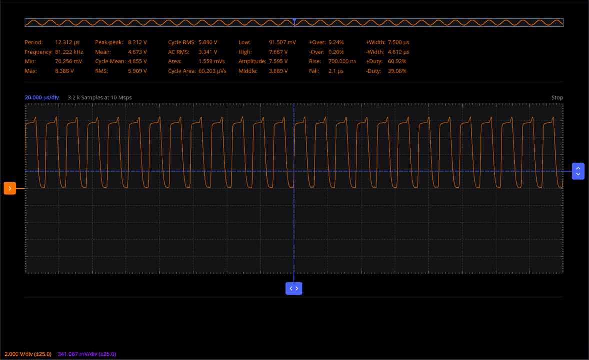
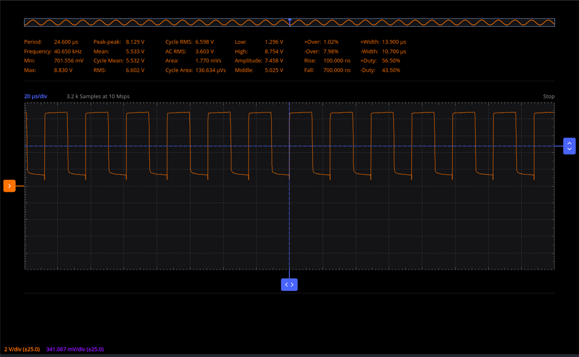
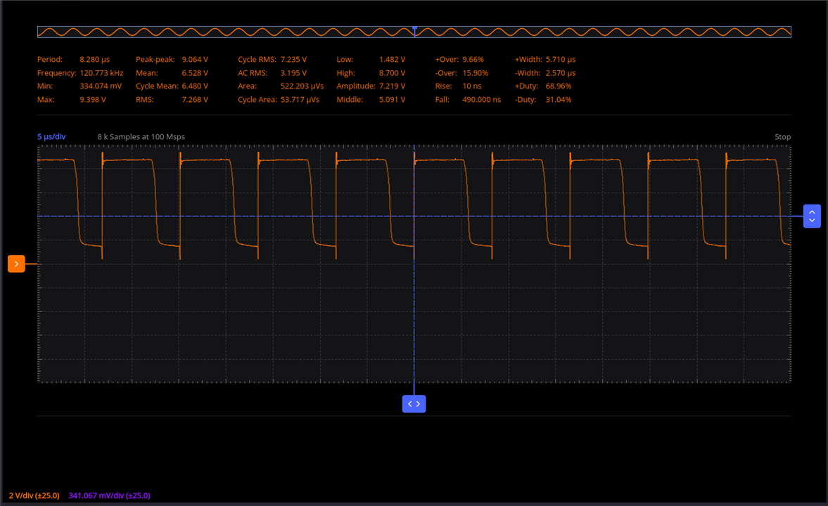
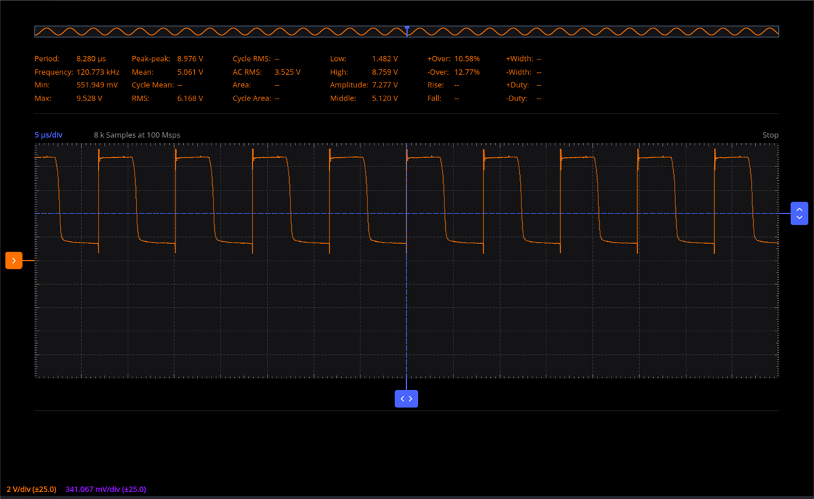
The results were fairly encouraging as I was able to reach 120kHz. Although it was not ideal.

{gallery:autoplay=false}P-Channel PWM Results

image

image

image

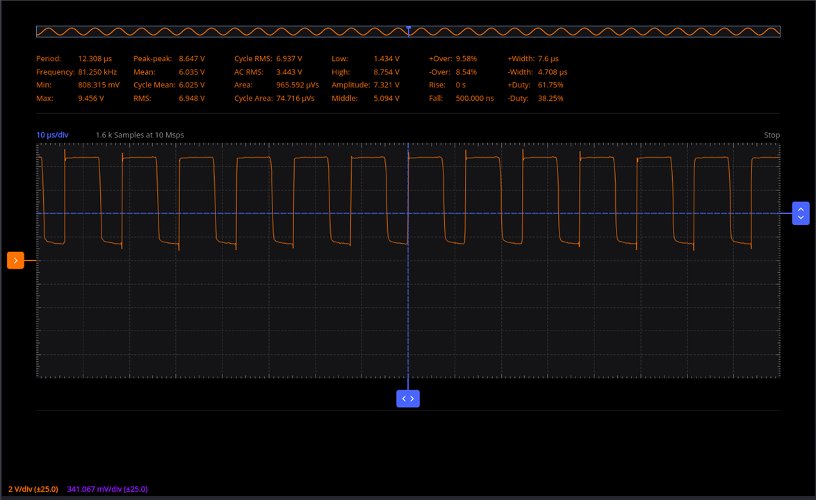
Then, after a little pondering, I came up with an improvement. By adjusting the PWM duty cycle to 30%:

image

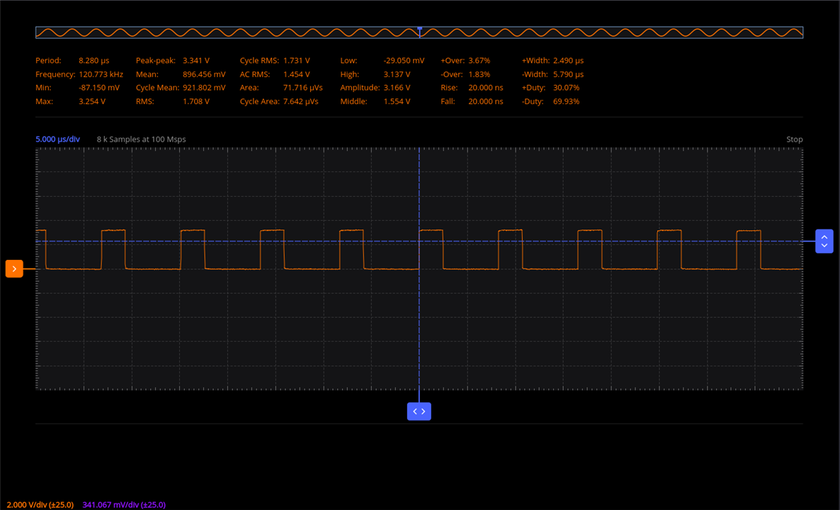
I was now able to get the desired square wave through this p-channel MOSFET. Happy days.

image

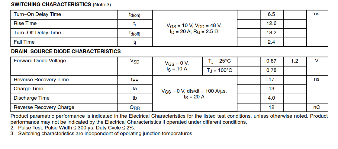
I’ll leave it up to you to decide whether this output meets expectations based on specifications shown above.

To close off my P-channel experiment, I decided as a quick exercise to compare this P-Channel MOSFET with others, based on timings alone. It seems there are some better than others.

Specified as typical in datasheets
Model Manufacturer Turn-on delay (ns) Rise Time (ns) Turn-off delay (ns) Fall Time (ns) Reverse Recovery Time (ns)
FDN5618P Onsemi 6.5 8.0 16.5 4.0
DMP10H4D2S Diodes Inc 3.3 2.6 8.4 4.9 17.8
BSS84AHZG ROHM Semiconductor 12.0 22.0 140.0 56.0
IRF5305PbF Infineon 14.0 66.0 39.0 63.0 71
BSS84P Infineon 6.7 16.2 8.6 20.5 23
TP0610K Vishay 20.0 ? 35.0 ?
NTR1P02L Onsemi 7.0 15.0 18.0 9.0

32.5

Closing Remarks

Now that I have obtained a better understanding of the behaviour of this specific P-Channel MOSFET, I feel reasonably confident that I can effectively handle the inherent instability of these flyback transformers in a properly controlled manner. The assumption here, of course, is that I can generate the required +100kHz PWM frequencies in a high voltage environment. For this I plan to use an opto-coupler. We'll how that goes in the next blog.

So to conclude, I have now moved beyond the stumbling blocks and onto the stepping stones. Hopefully I can find the time to achieve my objectives before the deadline.

  • Sign in to reply
  • shabaz
    shabaz over 1 year ago

    Hi Colin,

    As another project if you fancy it one day: it's possible to make the Pi Pico into a convenient test tool, using Jan Cumps  Pico SCPI labTool (PST). I didn't realize but now it's got a PST documentation wiki. It has PWM capability, although I believe we hard-coded the PWM frequency for now.

    The PWM can serve at least two purposes on PST; one is for an isolated DAC board (which will take that PWM and convert it to an analog output, hopefully on a couple of channels), but the DAC board still needs to be worked on (a schematic for a test board is done), and the other is to use it simply as a frequency or PWM output for general circuit stimulus!

    I wanted to add a display to it, which would be used for monitoring purposes (not for controlling, because that's too fiddly, it is better to control with SCPI, and see the current live measurements on the display), but then later realized that with PWM, there could be a need for directly controlling from buttons, since there could be occasions where it is desired to detatch from the PC, especially when working with high-voltage projects!

    Unrelated, I was working on a pico-sized GUI and button library in C++, to make pico-sized appliances (they don't need to be pico-sized! but I liked that Waveshare display/buttons board, it was a quick way of knocking up microcontroller based projects that need a bit of info display/control) , and at the time I tested it with PWM (using the hardware/pwm capability, not PIO). Very basic, the up/down controls on the mini joystick control the frequency, and left/right control the duty cycle, no acceleration etc for now. 

    I've not done much with it recently, the code is very ropey, but if anyone's interested and wishes to extend it, I'd be happy to stick the code somewhere. It's nothing special, but those rectangles on the display are all individual C++ text window objects! Each box is a mini text window, which automatically scrolls text if it exceeds the height of each box (e.g. you could have a multi-line box).

    You can see small bugs, like the white box isn't perfectly rectangular, there is an artifact just below where it says 56%.

    To keep the library simple, it only supports 3 or 4 font sizes. 

    image

    • Cancel
    • Vote Up 0 Vote Down
    • Sign in to reply
    • More
    • Cancel
  • jc2048
    jc2048 over 1 year ago

    Interesting blog. Maybe with all this good blog activity, Randel might let the challenge run on a bit longer.

    "Does this match the specification? I’ll leave it up to you to decide."

    Whilst the datasheet specification looks very impressive, switching characteristics are a secondary attribute: they depend very much on the test used to measure them. That's because the thing that slows is capacitance, and you partially get round that by throwing more current at the capacitance so that the voltage changes quicker.

    The manufacturer wants the part to look good in a comparison, so the test is designed to show the part at it's best within the limits the part is rated for. In the case of the NTD5867NL, they have the device switching 20A to 48V in the output circuit, and they're initially throwing several amps at the gate (4A in this case, if the gate is metal rather than heavily doped silicon). In your case, the output is very lightly loaded and the gate current is probably initially something like 100mA - the output pin of the Pico is driven high by an internal MOSFET with an on resistance of maybe something like 20-25 ohms. So you won't see the figures they are showing you on the datasheet.

    One thing that does help you is that the microcontroller pin driver is fast, so you aren't being slowed by the performance of the driver in the way Javagoza was with his discrete bipolar circuit. The limitation, though, is that you can only get the gate to 3.3V, so fine for switching lowish currents with a logic-level MOSFET, but may struggle switching higher currents.

    Implementing a digital control loop is quite difficult (but rewarding to look at because there are things that can be done digitally that would be impractical with an analogue loop). You might find it more straightforward to implement an analogue control system first (in a chip so that the difficult part has been done for you), get the converter working, and then move on to experimenting with digital control algorithms knowing you weren't fighting two things at once. Having the analogue system would also let you see how the controller deals with different scenarios, like the way the controller has to back off after quickly charging the output capacitor, if a light load isn't then taking the energy being provided, and would give you a benchmark for comparison with your own algorithm.

    • Cancel
    • Vote Up 0 Vote Down
    • Sign in to reply
    • More
    • Cancel
  • DAB
    DAB over 1 year ago

    Very good update.

    • Cancel
    • Vote Up 0 Vote Down
    • Sign in to reply
    • More
    • Cancel
  • BigG
    BigG over 1 year ago in reply to dougw

    Yes, I am pretty impressed by the Pico-Arduino PWM capabilities. I found that I could take it up to 2.45MHz before it started to lose shape a bit.

    image

    • Cancel
    • Vote Up 0 Vote Down
    • Sign in to reply
    • More
    • Cancel
  • dougw
    dougw over 1 year ago

    Nicely done with the Pico-Arduino PWM

    • Cancel
    • Vote Up 0 Vote Down
    • Sign in to reply
    • More
    • Cancel
element14 Community

element14 is the first online community specifically for engineers. Connect with your peers and get expert answers to your questions.

  • Members
  • Learn
  • Technologies
  • Challenges & Projects
  • Products
  • Store
  • About Us
  • Feedback & Support
  • FAQs
  • Terms of Use
  • Privacy Policy
  • Legal and Copyright Notices
  • Sitemap
  • Cookies

An Avnet Company © 2025 Premier Farnell Limited. All Rights Reserved.

Premier Farnell Ltd, registered in England and Wales (no 00876412), registered office: Farnell House, Forge Lane, Leeds LS12 2NE.

ICP 备案号 10220084.

Follow element14

  • X
  • Facebook
  • linkedin
  • YouTube