In this Blog 2, I will describe the flyback smps technology. When I had applied for this design challenge, I didn't thought of writing any special blog for this, as all materials are available on net but the motivation of writing specially a separate blog started with dis-agreements in the blog titled "What Is So Special About a Flyback Transformer?", where I had said flyback transformer is a transformer isolated buck converter and even a transformer isolated strictly buck converter!. Here i did mistake as flyback technically is derived only from buck-boost and is a transformer isolated buck-boost converter. How come i did mistake is explained in this blog. In simple words - I have used it as strictly step-down and the forward topology completely went out from my mind & I did this mistake with the flyback instead forward but both have f alphabet( this was brought into notice by Shabaz).
, in 'Fun with Flybacks: Building a 600V Supply'
because 'forward and 2switch forward' topologies are replaced by other topologies(half brige,full bridge, DAB(dual active bridge) ,MRC,LLC etc.). I haven't designed any SMPS using forward or 2 switch topology and this topology is hardly used in new (old systems may be based on & there could be new designs based on it as new design examples are based on it ), so these topologies (forward, 2switch) didn't came in my mind and it was mess with f alphabet. Also, to design a strictly buck converter, I have always used flyback as strictly buck for a decade.
Here on e14, I have found experienced engineers who have practically used flyback in high voltages or probably only in very high voltages (25 kV) in CRTs /old color TV sets, and thus, it is easy for them. Also, a recent blog titled 'Fun with Flybacks: Building a 600V Supply', I have found very interesing points using it in 600V supply or flyback supply, CRTs etc.
These blogs have brought lot of points and also there are few questions posted outside these blogs along with my question raised here in this blog, so all this I thought of making as a separate blog, as other doctors(phds or post-phds or even clinical bio-medical) or engineers may have the same arguments.
So, I will explain all this in this blog.
Firstly, I clarify, I m not acting here as some authoritative or oversmart on writing this as blog (or proposing as Talk), collecting all points and answering. Also, flyback is not my trademark.
My Background in SMPS
As mentioned in Blog 1
Of all the Flyback SMPS, I had designed or worked on, they were always strictly step-down but the buck-boost ones which I had designed, I (and the client or other graduate engineer who had wanted) had never called them as flyback buck-boost or flyback but they were called as simply buck-boost or interleaved buck-boost. Then other topololgies I had designed or worked on, were simply called as buck, multiphase buck, interleaved flyback (took for a buck only not buck-boost), SEPIC, charge pump, Ćuk, multiphase flyback(again for a buck not buck-boost), interleaved boost, 2 phase flyback, 3 phase flyback, 6 phase flyback, 9 phase, 12 phase, 24/48-pulse, Novel ß boost (self claim as shown here), Novel ß Inverter, Novel ß Power Boost, LLC, CLLLC, full bridge, phase shift full bridge,half bridge, push pull; on all these I had done calculations, whether complete or incomplete or only on paper, wherever the flyback word was used, it was always strictly step-down, in these particular designs.
With the clearance Flyback(FBT) SMPS is a transformer isolated buck-boost(by derivation), there arises again the need to write this blog because
- All the kit components of this design challenge of flyback transformers are strictly step-down.
- Why Flyback transformers as sold as step-down. This can be seen by primary and secondary voltage specifications, where the secondary is always down?
- All manufacturers selling Flyback transformers as strictly step-down.
- Nearly all mobile chargers or laptop or battery chargers use flyback transformers and are always strictly step-down. Why they are called so?
- The Engineers on e14, worked on FBT which were strictly boost (to even 25 kV) but they only called them as flyback FBT transformer not flyback buck-boost transformer, when these could be easily and safely called as only boost. When now there is Flybuck, why not these called Flyboost.
- If flyback is a buck-boost topology, why the strictly boost are called as flyback transformers and why the strictly step-down are also called as flyback transformer and of course buck-boost are also called as flyback transformers.
- It thus also becomes necessary to write, as to decide 'Where are Flyback Transformers are used?' because applications can be different for strictly boost or strictly step-down or strictly buck-boost.
- Some also gets confused whether flyback transformer is DC-DC or AC-DC.
- There are some very good arguments mentioned in the 'collection of points'.
- There are terminologies used Flybuck, Flyback, fly-buck-boost, flyback boost circuits, flyback circuits, inverting Fly-Buck-Boost Converter- What are these? Are they same?
- There is confusion which arises from application notes itself, as some notes eliminates boost and mentions the use is limited to buck and flyback conversions.
- There are some variations in buck- boost topology but they are not called as flyback. Why?
- Similarly, if one using boost topology, one do not use word 'flyback' in boost, unless 'flyback boost circuits'. Why
- There is also boost-buck topology. Is it same as Flyback?
Thus, it's still a confusion, a dilema, and I have used 'quandary' word instead 'dilema' or 'confusion', which I will clear it in this blog.
Besides this, I will go into detailed other buck-boost and boost-buck topologies, theory of operation, the design examples are in next blog; all these again are elementary for school/diploma/graduate.
Blog Organization
This blog is organized as : I have divided this blog in three sections.
The first section is titled as Flyback Quandary, which is divided in 2 sub-sections - (a) Collection of Points, (b) Uses in Today's Scenario.
The 2nd section is titled as Topologies & Theory of Operation.
The 3rd section is the Conclusion of flyback quandary. This conclusion is add-on besides my comments/remarks and answers along side in Section I, II. So,I have answered this 'flyback quandary'
- Along side comments/remarks
- Section I. 10-50 KV FBT
- Section III
- Section III,Conclusion of Part-B
- Section III, Answers of Part A
Table of Contents
I. Flyback Quandary
A. Collection of Points
- Where are Flyback Transformers used ?
- Arguments : It is Often Step Up
- Arguments from Blog Fun with Flybacks: Building a 600V Supply
- Angelfire : Dissection Of A Flyback Transformer With An Internal Diode
- Old TV FBT
- LOPT
- Article : Kevin Chen
- 10-50 KV FBT
B. Uses in Today's Scenario
- Kit Components & Other Manufacturers
- TVs and Monitors
- Tool & eBike Chargers
- Computers & Servers
- LED Driver
- IoT, Smart Home and Building Automation
- Meters and Industrial Equipment
- USB PD Adapters
II. Topologies & Theory of Operation
III. Conclusion of Flyback Quandary
Videos
- 750316586r01 Wurth Elektronik Transformer- 3058.ti1.mp4
- video of broken PCB of color TV with FBT
- Volt-Sec Balance
- Quadrant Switch Operation
- Buck
- Boost
- Buck- boost
- Flyback
I. Flyback Quandary
In this section, I have taken all points as said and answered them along side with comments.
I have already clarified the mistake above and yes, flyback is derived and is a transformer isolated buck-boost, so its story repetition is not required in this section. This section is organized in two sub-sections- Collection of Points and Uses in Today's Scenario.
A. Collection of Points
So, firstly I start with where flyback transformers are used.
1. Where are Flyback Transformers used ?
1. As I have mentioned here
My Comment
Here all the 72 transformers (besides all other transformers I have worked on) are flyback transformers and strictly buck not buck-boost.
2.
3. The use of flyback transformers as mentioned by experienced e14 engineers were in CRT, old TV Sets, color TV sets. This I am keeping as separate in the list of use of where FBTs are used because these FBTs are upto 35 kV or 50 kV. I have addressed this in "Section III. Answers of Part A- All related to Old TVs- flyback boost, often step up, and step up, 10 kV or 50 kV, from following blogs "
4. FBTs are still used in TVs and Monitors but with a lower voltage level(neither at 10kV nor 50 kV).
5. FBTs are used in tool chargers, eBike chargers, computers & servers, LED driver, IoT, smart home automation, building automation, meters, industrial equipment, USB PD Adapters and gate drive transformers. I will take all of these in this blog2 except gate drive transformers which I will explain in blog 4.
2. Arguments : It is Often Step Up
In this part, I am mentioning 6 arguments or disagreements and 1 question, as promised.
Following arguments or disagreements, I have taken from the blog titled "What Is So Special About a Flyback Transformer?". Other doctors or engineers may have the same argument.
- Step-up flyback circuits
- Possible step up operation when turn ratio is properly set.
- Wikipedia : Buck-Boost
- Whether it is buck or boost depends on the turns ratio.
- Texas Instruments PMP30165
- Often Step Up
- Question
My Comment
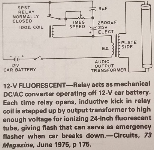
Yes, shabaz, but nothing is changed if it was 1975 or 2024, that is, in approx 50 years or more. Here, you have mentioned two circuits . One in the picture, which is a 12V fluorescent and the other in old TVs, which you have mentioned as flyback boost.
In 12V fluorescent (Source : your attached pic caption),
- the DC-AC which nowadays as you know is called an inverter, this function is achieved using relay which can be seen as 'SPST Relay NC', 100Ω coil. So, the inverter function was achieved using MOSFETS or IGBTs or SiCs (BJT also obselete).
- The inductive kick (which is the result as relay is opened) is stepped up using 'Audio output Transformer' to high enough voltage, the HV not mentioned how much Volts or kV but you can estimate as the complete circuitry is powered by 12V car battery. This stepped up voltage to HV ionizes 24inch fluorescent tube, which gave flash and acts as an emergency flasher when car breaks down.
- This was in 1975 and even if you do the same in 2024 or 2030, it would be exactly said in the same way as it was in 1975 or earlier.
- Here, inductive kick is used and no flyback
For old TVs, camera flash, pls see below as flyback was used to generate even 35 kV or 50 kV. But again, even if you use the same circuitry of big color TV sets today in 2024 or 2030, it would be exactly said in the same way as it was in 1975 or earlier-flyback FBT. Why were or are these called as 'flyback boost', for this, pls see in 'Section I 10-50 KV FBT and Section III'.
2. Possible step up operation when turn ratio is properly set.
My Comment
Yes, for step-up, turns ratio has to be adjusted. But in a SMPS, flyback transformer, the turns ratio are fixed when delivered as a product, and it is a buck-boost.
So, once you have a physical object, here a transformer, the windings cannot be stepup or step-down, the FBT works on the principle of duty ratio. I have explained this in video flyback-1.
For a regular step down

For a regular step-up

3. Whether it is buck or boost depends on the turns ratio.
My Comment
Yes, turns ratio is used to step-up and step-down, ONLY FOR regular transfromers.
But when a flyback transformer is purchased, say as in the kit provided only like in blog 1, I have mentioned - SMPS Flyback Transformers - BOURNS 094929, BOURNS 063929, BOURNS 063932, BOURNS 093830, BOURNS 063934, BOURNS 094931 and BOURNS 094932.
These are all having fixed number of coil turns, so for a general step-up, additional coil turns are needed and similarly for a general step-down, lesser coil turns are needed; both which cannot be changed after they are products.
The flyback transformer being derived from buck-boost can still do boost or buck. How ? I have explained this in video flyback-1. When a flyback transformer (FBT) is used, output voltage magnitude can be less than that of the source or greater than the source. This is not achieved based on number of turns but the FBT works on the principle of duty ratio, so the output voltage magnitude depends on the duty ratio of the switch.

If duty ratio D > 0.5, that is D > 50% the output voltage is larger than the input voltage.
If duty ratio D < 0.5, that is D <50% the output voltage is smaller than the input voltage.
Therefore, flyback transformer is able to give the capabilities of both buck and boost converters.
My Comment

Below quote from Wikipedia says, Buck-boost is equivalent; It not saying is the buck-boost

Flyback is derived from buck-boost(no doubt) and I have derived in the video flyback-1, from buck-boost to transformer isolated buck-boost; converted single inductor of buck-boost to transformer (this in actual is the derivation process).
My Comment
I.
The PMP30165 reference design is an inverting Fly-Buck-Boost Converter NOT FLYBACK CONVERTER and this particular PMP30165 is 5W Isolated Triple Output Inverting Fly-Buck-Boost.
Files can be downloaded from here : TI PMP30165 and Flybuck 750316586r01 Wurth Elektronik Transformer
Below is screenshot from Texas Instruments (TI),
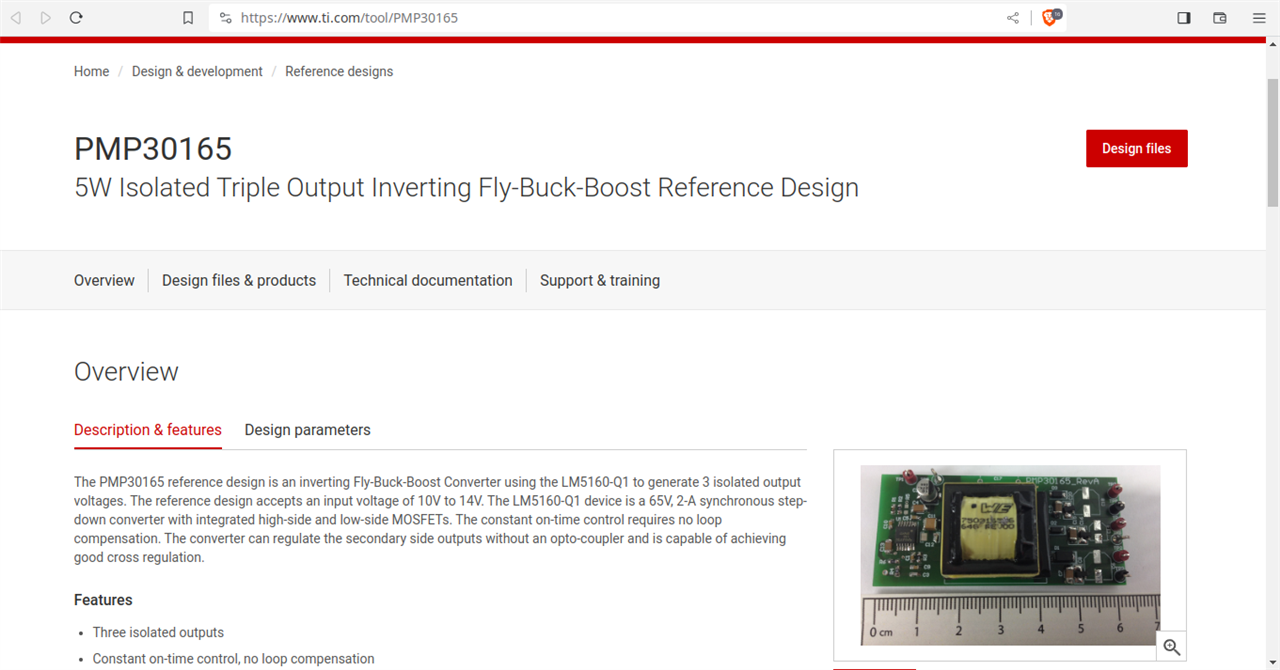
The input and output voltage specifications are :
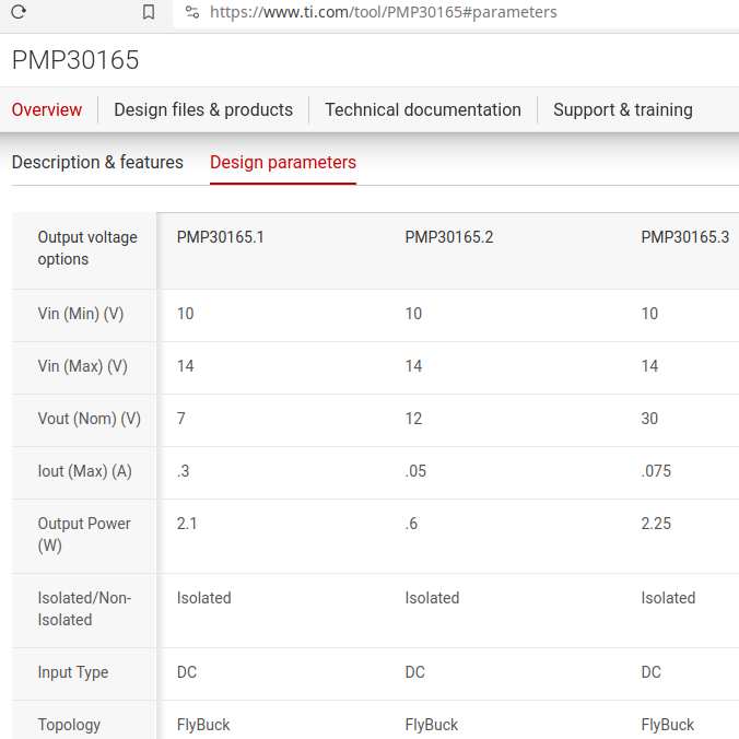
As I see above (in screenshot),
in PMP30165.1, output voltage is lower than minimum input voltage.
in PMP30165.2, output voltage is higher than minimum input voltage but lower than maximum input voltage.
in PMP30165.3, output voltage is higher than both minimum input voltage and maximum input voltage.
T1 1 150uH 750316586r01 Wurth Elektronik Transformer, 150 uH, TH

Here Texas Instruments (TI) not saying or said, it is a flyback; for all three output variations- Flybuck
Below is from Wurth Elektronik Transformer,
It can be seen the transformer 750316586 or 750316586r01 is in category of Isolated Buck Transformers and Fly-Buck, the voltage levels already mentioned above.
So, this is out of discussion but I have mentioned about this in Conclusion.
The more relevant TI examples for discussion are below.
II.
Below is another screenshot from TI controller UCC28711
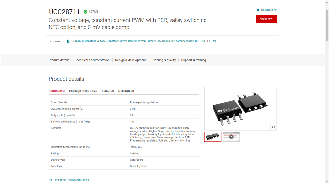
In the topology, you can see - buck and flyback.
TI, is not writing it as buck, boost, flyback. Why boost is not mentioned here, when flyback is a buck-boost derived and can be used to boost by definition.
The answer is simple, this particular controller UCC28711 cannot be used to boost with a flyback transformer. If a FBT is used, it can do only buck or flyback, that is, stritcly buck, not boost with this particular controller UCC28711.
Thus, in this case, the duty ratio as i have mentioned above would be always < 0.5 or less than 50 %.
III. Following is other screenshot from calculator - Flybuck / Flyback Calculator
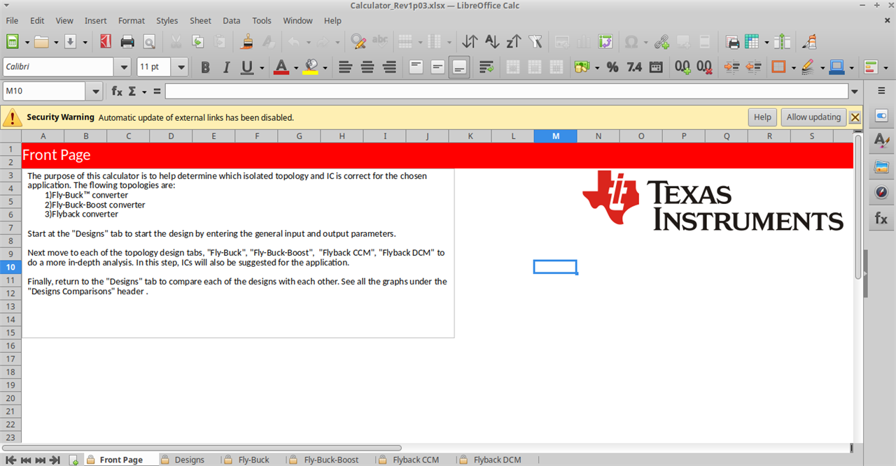
Here you can see, there are 4 topologies mentioned
- flybuck
- flybuck boost
- flyback CCM
- flyback DCM
My Comment
Flyback converters for voltage transformation and circuit isolation. -Yes.
(often, step up) - No.
In the old sceraios, like color TV sets, you can say so but in Section II- Uses in Today's Scenario, you will see number of applications, and all are step-down (rather strictly step-down).
7. Question
My Comment
Pls see 'Section III, Answers of Part A'.
3. Arguments from Blog Fun with Flybacks: Building a 600V Supply
3.1
- Angelfire : Dissection Of A Flyback Transformer With An Internal Diode
- flyback transformer from a scrapped computer monitor
- LOPT
My Comment : Pls see in 'Section I. 10-50 KV FBT and Section III'.
3.2 Flyback circuit used to achieve 600 V
My Comment : Pls see in 'Section III, Answers of Part A'.
3.3
My Comment : Pls see in 'Section I. 10-50 KV FBT and Section III'.
3.4
My Comment : Pls see in 'Section I. 10-50 KV FBT and Section III'.
3.5
My Comment : Pls see in 'Section I. 10-50 KV FBT and Section III'.
3.6
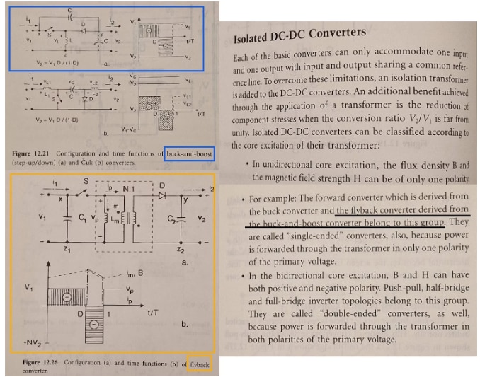
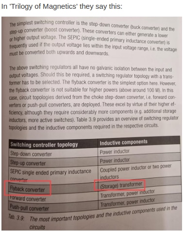
My Comment
Thanks for attaching this, and as i said, forward topology went completely out from my mind , which I have mentioned above.
3.7
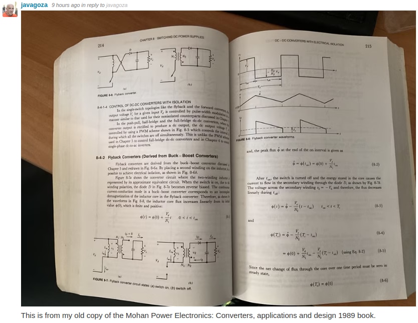
My Comment
Thanks for attaching this, and as said, forward topology went completely out from my mind , which I have mentioned above.
3.8
My Comment : Pls see in 'Section III, Answers of Part A'.
4. Angelfire : Dissection Of A Flyback Transformer With An Internal Diode
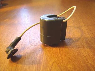
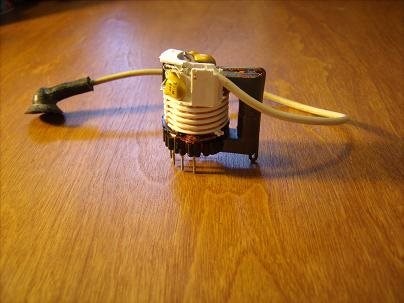
Following three images are from this article "Dissection Of A Flyback Transformer With An Internal Diode", which shows the usage of flyback circuits to generate high voltages, that is strictly boost.

Source : https://www.angelfire.com/oh3/ebjoew/Flyback.html
Fig. 4.1 : flyback transformer with its external diode
Source : https://www.angelfire.com/oh3/ebjoew/Flyback.html
Fig. 4.2 : Flyback Case
Source : https://www.angelfire.com/oh3/ebjoew/Flyback.html
Fig. 4.3 : Internals of Flyback Case with plastic shell removed
In this flyback case, two capacitors, diode, primary windings and secondary windings are enclosed.
My Comment
The article do not mention anything of the voltage range but it is HV flyback transformer and strictly boost FBT. But diode looks of 600W, a transient voltage suppressor diode, with breakdown voltage of 22V (typical), and maximum temperature coefficient of 0.092 %/°C.
Pls see Section I. 10-50 KV FBT and Section III
5. Old TV FBT
From customcoils - here, they have mentioned FBT for generating voltages ranging from 10 kV to 35kV, and following FBTs are mentioned :
- 6-8kV AC Flyback Transformers:
- 10kV AC Compact Flyback Transformer
- DC Flyback Transformer
- Disc-shaped AC Flyback Transformer
- DST flybacks (Diode-split Transformers)
My Comment
This is in rhythm with '3. Arguments from Blog Fun with Flybacks: Building a 600V Supply', where experienced e14 engineers have used 10 kV or 25 kV.
For more, Pls see in 'Section I. 10-50 KV FBT and Section III'.
6. LOPT
A flyback transformer (FBT) was populary known as line output transformer (LOPT) and as per Wikipedia
Following three images are also from Wikipedia Flyback transformer ( Source: https://en.wikipedia.org/wiki/Flyback_transformer)
Fig 6.1 : An old style flyback transformer producing an arc

Fig 6.2 : Modern CRT television flyback transformer with integral tripler

Fig 6.3 : Example of current waveforms in a flyback transformer
My Comment
With the article it's mentioned FBT are still used to generate even 10 kV !
And, this is in rhythm with
- 3. Arguments from Blog Fun with Flybacks: Building a 600V Supply
- 4. Angelfire : Dissection Of A Flyback Transformer With An Internal Diode
- 5. Old TV FBT
This same article also reveals the reason why this is FBT as it denotes this FBT as 10 kV SMPS (switched-mode power supplies)
In the previous point 5, FBT generated upto 35 kV but here LOPT/ FBT were used to generate upto 50 kV due to requirement by CRT (cathode ray tube) .
A large color TV CRT may require 20 to 50 kV with a horizontal scan rate of 15.734 kHz for NTSC devices and 15.625 kHz for PAL devices.
Pls see in 'Section I. 10-50 KV FBT and Section III'.
7. Article : Kevin Chen
This article is mentioned on the design challenge main page under Technical Resources Everything You Should About Flyback Transformer and is last updated on October 22, 2023.
1) Here the author (Kevin Chen - Founder / Writer at Rantle East Electronic Trading Co.,Limited) has mentioned -
There are three types of flyback transformers. These include:
1) Forward Converter Flyback Transformer
2) Reverse Converter Flyback Transformer
3) Half-Bridge Converter Flyback Transformer
But
- Forward Converter and Flyback Converters are different and are different topologies
- Reverse Converter and Flyback Converters are different and are different topologies
- Half-Bridge Converter and Flyback Converters are different and are different topologies
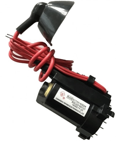
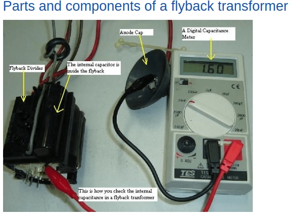
My Comment
Here the author has classified three more types of flyback transformers - Forward Converter Flyback Transformer, Reverse Converter Flyback Transformer and Half-Bridge Converter Flyback Transformer. This may be due to circuit configuration similarity on using the design of Forward Converter, Reverse Converter and Half-Bridge Converter with Flyback Transformer.
As such I don't have practical experience, for designing 25 kV or 50 kV.
For more, Pls see in 'Section I. 10-50 KV FBT and Section III'.
8. 10-50 KV FBT
All related to Old TVs- flyback boost, often step up, and step up, 10 kV or 50 kV, from following
- 2. Arguments : It is Often Step Up Step-up flyback circuits
- 3. Arguments from Blog Fun with Flybacks: Building a 600V Supply
- 4. Angelfire : Dissection Of A Flyback Transformer With An Internal Diode
- 5. Old TV FBT
- 6. LOPT
- 7. Article : Kevin Chen
All this brings more questions
- Why FBT required instead Conventional Transformer ?
- Why were they called flyback when they are strictly boost ?
- Why these are needed to be called as flyback boost when other boost circuits are not called flyback boost!
- Can these be called as High Voltage transformers or power transformers?
- What role these flyback or HV Step up FBT has ?
- Why these are called, even at 10kV or 50 kV, as FBT SMPS
Before I answer this here and in Section III, it is necessary to understand high voltage or very high voltage as both SMPS and high voltage comes from hardcore electrical engg.
8.1. Can these be called as High Voltage transformers or power transformers?
This question I have placed myself, and as mentioned LOPT FBT are of 50 kV, which is very high voltage in layman terms, and it has to be understood first.
Before answering this, I first explain what a high voltage is ?
In layman terms, even 110 VAC or 230 VAC Mains or 400/415/440 VAC is considered high voltage as it can cause an electrical shock and can even kill. Some call, a high-voltage transformer has voltage rating of greater than 33 kV.
But in electrical engineering, even a 11kV is a medium voltage transformer.
Voltages Classification :
1. According to Electrical Engineering standards, there are three types of transformers types-
- Distribution transformers: rated up to 69 kV
- Power transformers: rated from 69 kV to 230 kV
- Extra-high-voltage (EHV) transformers: rated above 230 kV
2. Second Classification is
- Low Voltage (LV): up to 1000V.
- Medium Voltage (MV): between 1000 V and 45 kV.
- High Voltage (HV): between 45 kV and 230 kV.
- Extra High Voltage (EHV): from 230 kV and above.
3. IEC voltage range
- Low voltage : 50 V to 1000 V
- High voltage : > 1000 V
I have mentioned, general voltage classifications. Different regions have different ranges like
1. India
- Low Voltage 50 – 1000 V
- Medium Voltage 1 kV – 100 kV
- High Voltage 100 kV – 345 kV
- EHV Voltage 345 kV – 765 kV
2. USA
- Low Voltage - upto 600V
- Medium Voltage - 601 V - 69 kV
- High Voltage - above 69 kV
3. Canada
- Low Voltage - upto 750V
- Medium Voltage - 750 V - 46 kV
- High Voltage - above 46 kV
Thus, whether 10kV (as mentioned by wikipedia as high voltage) or 50 kV, falls in which category is neither debate of this blog nor my authority of discussion nor my authority of categorizing it
but for my discussion, I will use layman voltage which can cause shock as high voltage.
8.2 Distribution Transformers vs FBTs
I have mentioned the classification above, so as to use these on flyback transformer. As can be seen that
- Distribution transformers: rated up to 69 kV
but these are called as distribution transformers and not flyback transformers and in general loose speaking, high voltage/very high voltage, power transformers.
These distribution transformers are always 3 phase and can if voltage range crtiteria is to be seen, it will comprise 10 kV FBT, 25 kV FBT, 35 kV FBT, 50 kV FBT.
But the FBTs can never be said as distribution transformers, Why ?
Because distribution transformers are always 3 phase and FBTs are single phase, we will see the internal structure of FBT in 8.2.
The distribution transformers are generally connected in delta-star,Δ-Υ but FBTs are not.
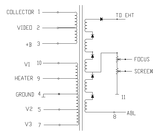
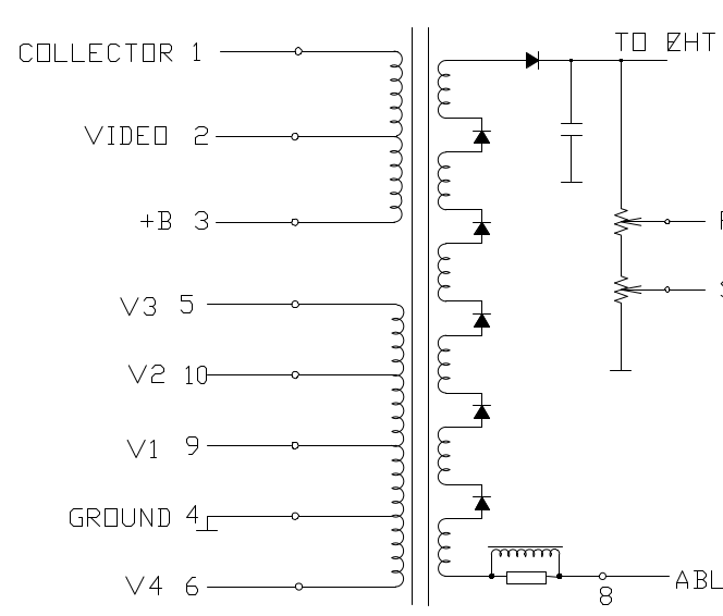
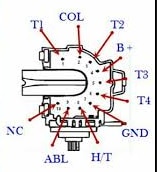
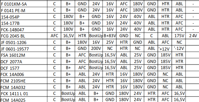
8.2 CRT FBTs and Schematic
Following is the list of some of the FBTs for CRT available in the market,to this date of 17 Jan 2024.
 JF0501-19587
8-598-998-00
BSC27-0101Q
1-439-421-00
BSC25-Z2706
BSC26-2631S
JF0501-32611
JF0501-38501
JF0501-38534
BSC25-N0379
BSC25-T1010A
BSC26-T1083B-2
BSC26N40A
8-598-960-00
FCM20B062N
1-439-421-11
154-277V
6174V-6002A
BSC22-2403C
BSC26-2639S
BSC26-2670S
BSC27-0101V
CF0801-3701
F0067PEM
F0069PE-M
JF0101-0101
JY0301-0292
TFB4067BD
FCA173
| {gallery}FBT Schematic |
|---|
 |
 |
 |
 |
 |
 |
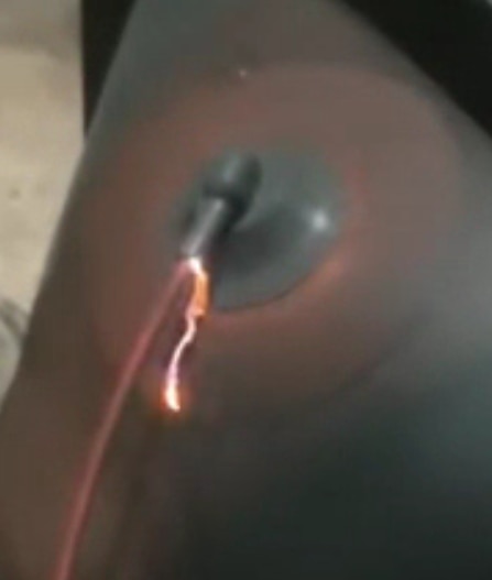
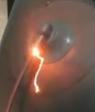
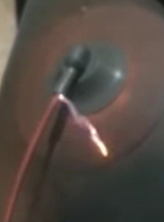
Below is video of broken PCB of color TV with FBT
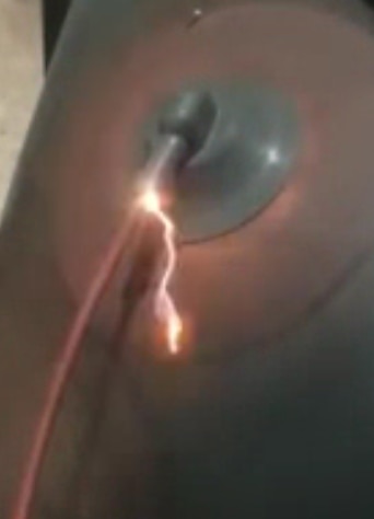
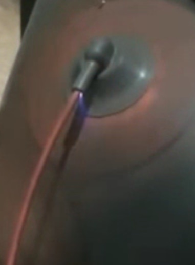
FBT ARCs
| {gallery}FBT arc |
|---|
 |
 |
 |
 |
 |
 |
B. Uses in Today's Scenario
1. Kit Components & Other Manufacturers
1.1. Kit Components
1) From 'Blog 1' , if we see the kit components which are SMPS Flyback Transformers, all have step-down voltages.
2) There can be more confusion as in blog1 under '3. Kit Remarks', I had written
BOURNS has provided 4 types of flyback transformer, which are classified according to usage - Gate Drive Transformer, Automotive Grade DC-DC Flyback Transformer, SMPS Flyback Transformer,Common Mode Choke
I did not mistake calling Gate Drive Transformer, Common Mode Choke under FBT as the contest is of FBT but flyback I have separately used with Automotive Grade DC-DC Flyback Transformer and SMPS Flyback Transformer; and they are gatedrive and cm chokes only.
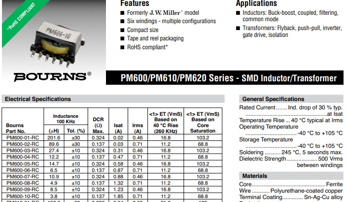
To add confusion, see below screenshot. Under Application and under 'Transformers'- you can see flyback and gate drive both!
1.2. Bourns Other Transformers
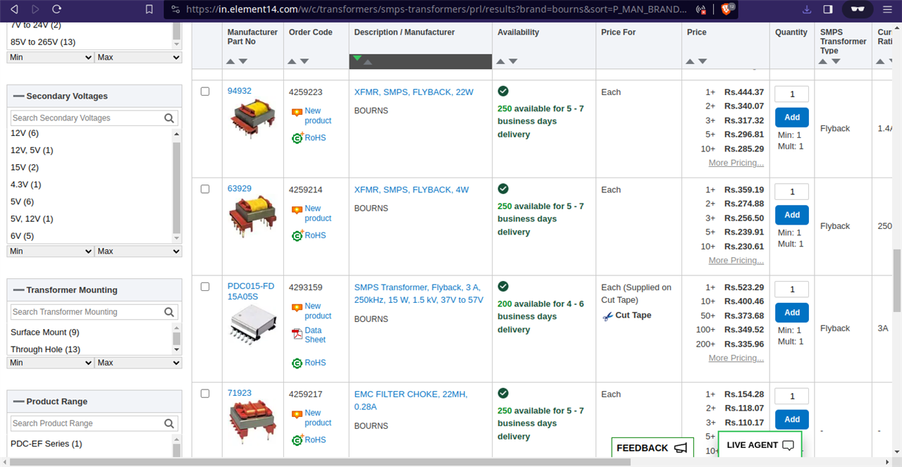
As can be seen the secondary voltages are limited to 15 V, whereas primary voltages are always higher.
1.3. Other Manufacturers/Competitors
- Coilcraft
- Power Integration
- Pulse Electronics
- Wurth Elektronik
- Misc
1.3.1 Coilcraft
Below is the screenshot from Coilcraft manufacturer
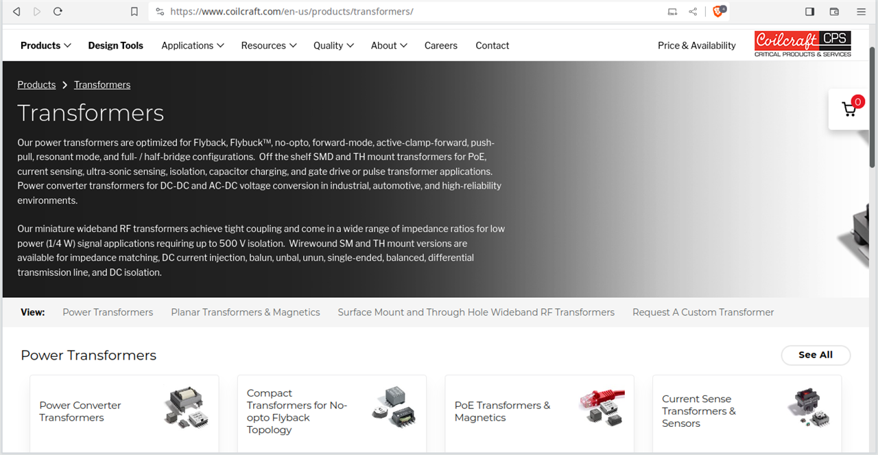
My Remark :
If we see from this page, Coilcraft categorizes its power transformers as
- Flyback,
- Flybuck
,
- no-opto,
- forward-mode,
- active-clamp-forward,
- push-pull,
- resonant mode, and
- full- / half-bridge configurations
- Compact Transformers for No-opto Flyback Topology
The word 'power transformers' can be seen from the screenshot and obviously here power transformers do not mean the power transformers mentioned in the previous section under 'Voltages Classification' ( Power transformers: rated from 69 kV to 230 kV).
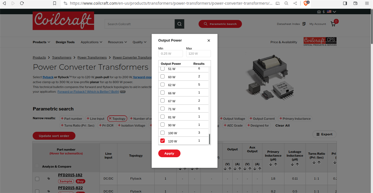
Also, it can be seen clearly on the screenshot

- flyback or flybuck
for up to 120 W,
- push-pull for up to 200 W,
- forward-mode for half-bridge, full-bridge, or active clamp up to 300 W,
- low-profile planar for up to 800 W power.
The flyback is limited upto 120 W, whereas in the beginning, I have mentioned limited upto 150 W.
Below is the screenshot from Coilcraft, which displays only 1 transformer with 120 W (though Coilcraft has many transformers based on flyback topology only when other wattages are considered).
And in the following screenshot, it can be seen
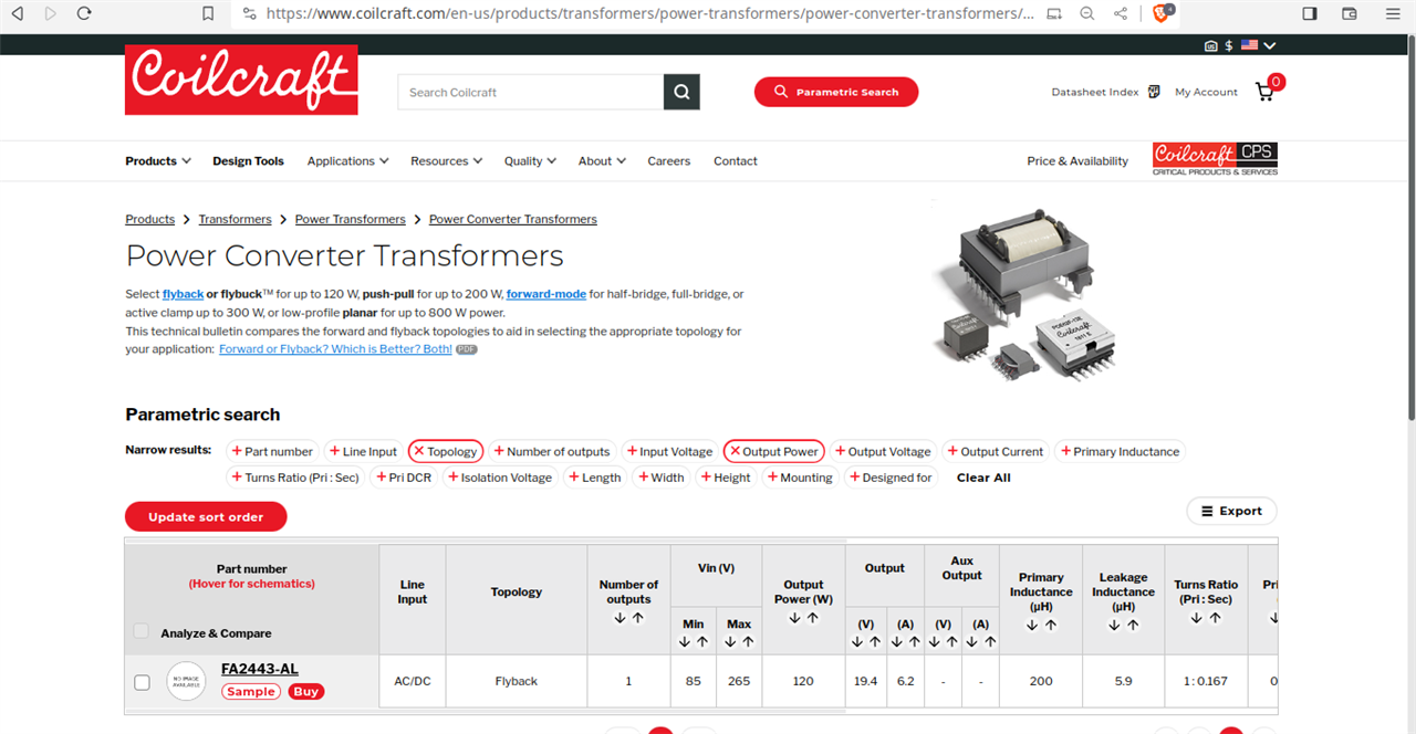
The above screenshot says the input is AC voltage from 85 VAC - 265 VAC and the output is 19.4 V , 6.2 A = 19.4 x 6.2 W = 120.28 W.
The input voltage is clearly < 265VAC and the output voltage is clearly 19.4V but the above transformer is classified under 'power transformer' !
1.3.2 Power Integration
Below is the list of ICs, not transformers, made by Power Integrations
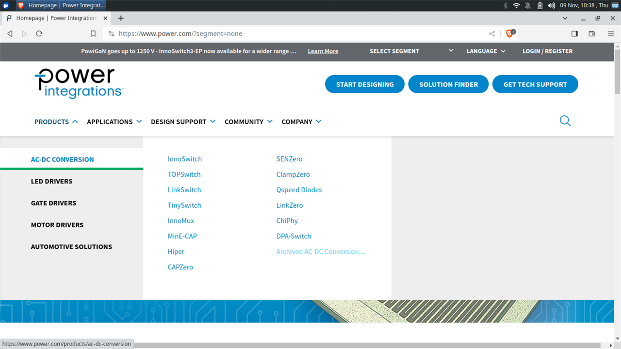
My Remark :
I am only mentioning which are related to flyback topology, as some ICs support boost and hybrid topologies like Hiper which supports CCM/DCM boost PFC, Two-Switch Forward and resonant LLC half bridge ; SENZero for two-switch-forward/LLC/half/full-bridge converters
- InnoSwitch off-line flyback switcher IC --- limited to typical 100W.
- InnoSwitch4-CZ - limited to 220 W with Quasi-Resonant Mode.
- LinkSwitch : are optimized for isolated flyback power supplies and, in a non-isolated variant, for low-current offline buck applications --- limited to typical 15W
- LinkSwitch-HP --- limited to 153W
- TinySwitch flyback power supply controller --- limited to 25W
- ClampZero --- limited to 220W
1.3.3 Pulse Electronics
1.
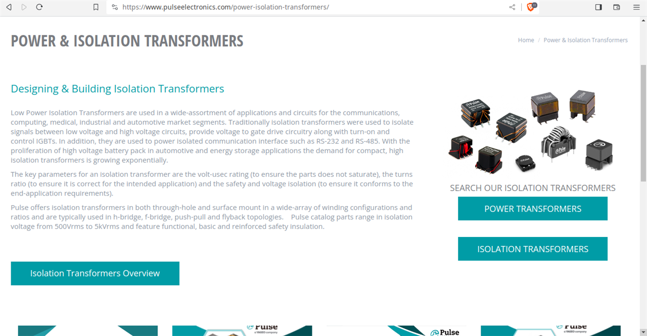

The above screenshot displays again power transformers and again obviously here power transformers do not mean the power transformers mentioned in the previous section under 'Voltages Classification' ( Power transformers: rated from 69 kV to 230 kV). Moreover, the transformers from other topologies are only upto maximum of 10 kW, which is too less than 69 kVA or 69 kW.
2.
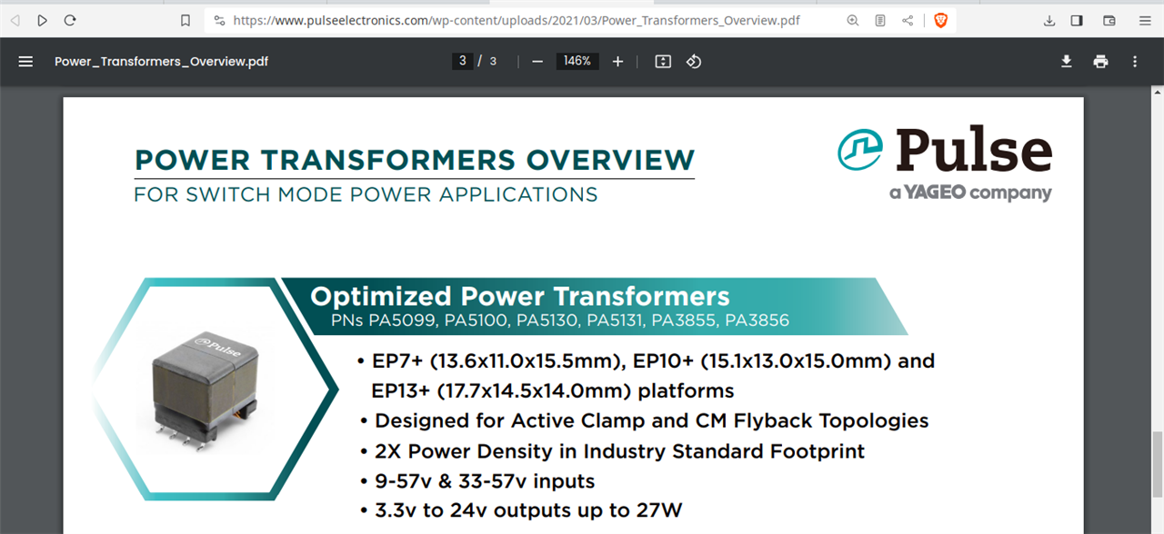
The above screenshot again use word power transformers (optimized) and it is clearly mentioned the input voltage is < 57 V , the output voltage < 24 V and the maximum output is 27 W.
3.
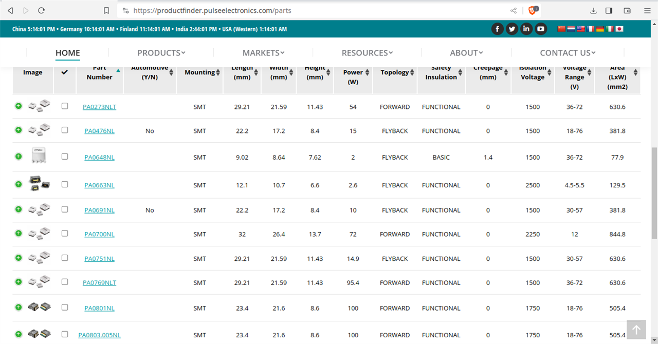
The screenshot displays various transformers based on different topologies under 'power transformer'
4.
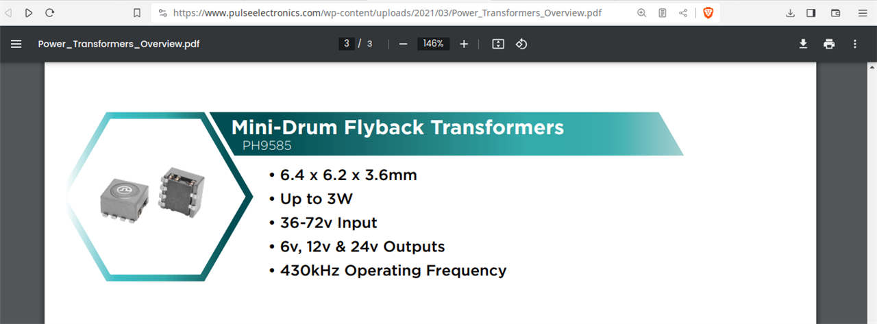
The screenshot shows the flyback is limited to 3W, with input < 72 V and maximum output of 24 V.
5.
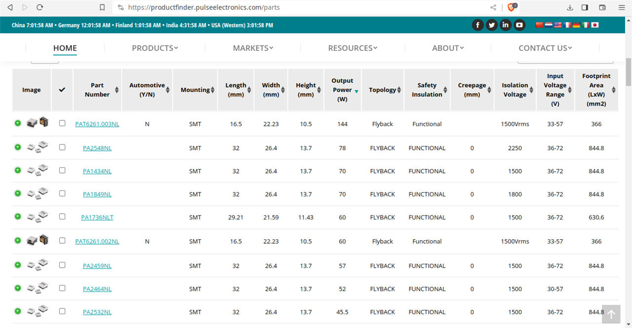
The above screenshot again shows the maximum flyback transformer (under power transformer) by 'Pulse Electronics' is 144 W, with input voltage < 57 V, maximum output voltage 12 V and max. current of 12 A (but at output voltage of 3.3V).
1.3.4 Wurth Elektronik
1.
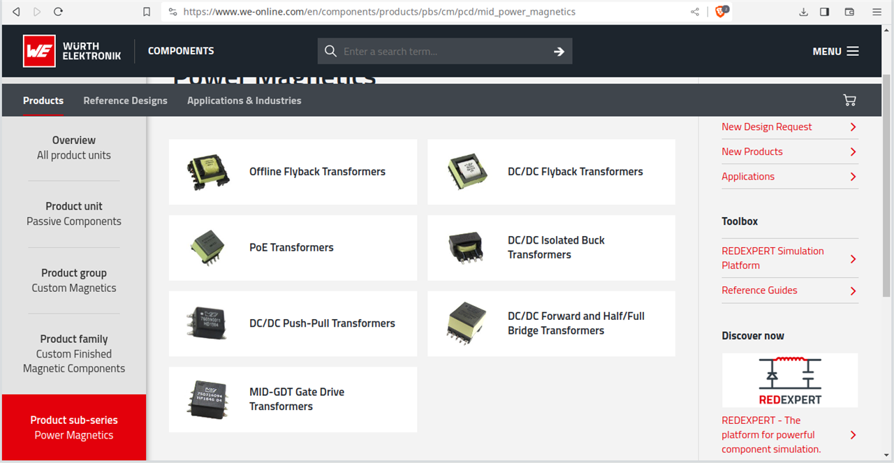
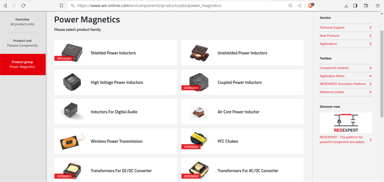
The above 2 screenshots displays 'power magnetics' under which transformers for DC-DC and transformers for AC-DC can be located.
2.
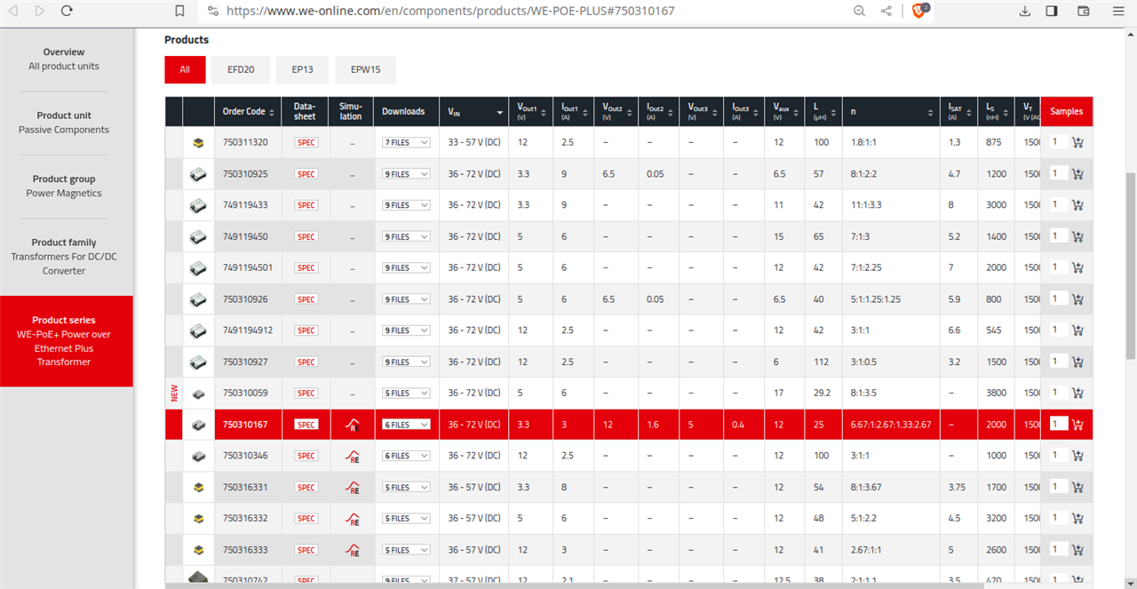
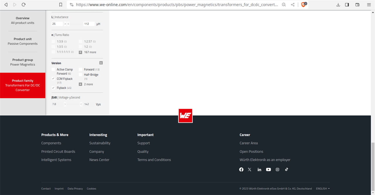
Under the category 'Transformers for DC-DC', Wurth Elektronik offers two variants for flyback - flyback and CCM flyback,
the maximum VDC is 72 VDC with max. output = 12 VDC
3.
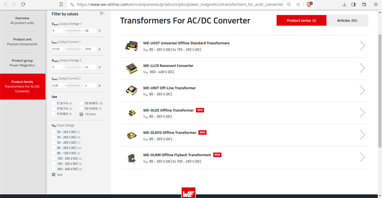
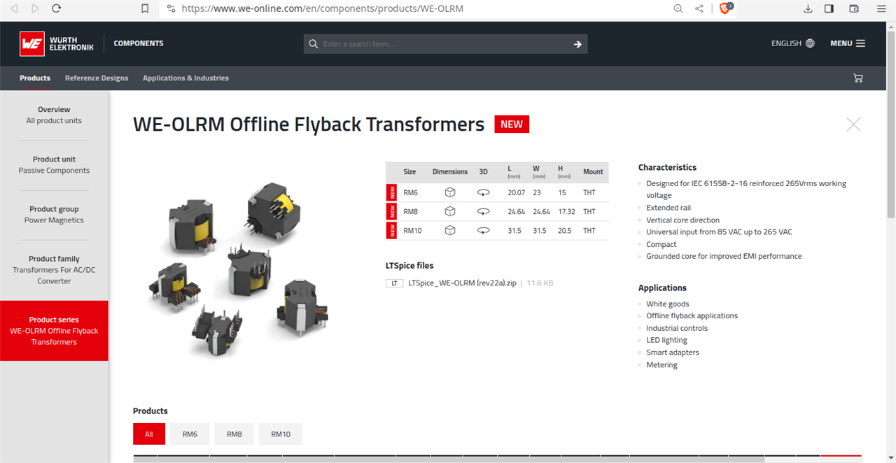
One can see 'Offline flyback applications', so with AC voltage, now a word 'offline' is suffix with flyback.
4.
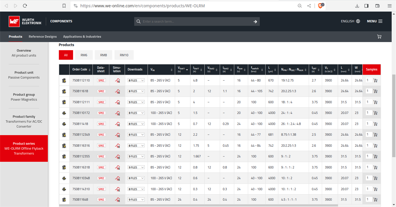
Under the category 'Transformers for AC-DC', the maximum output voltage is 24 VDC.
1.3.5 Misc
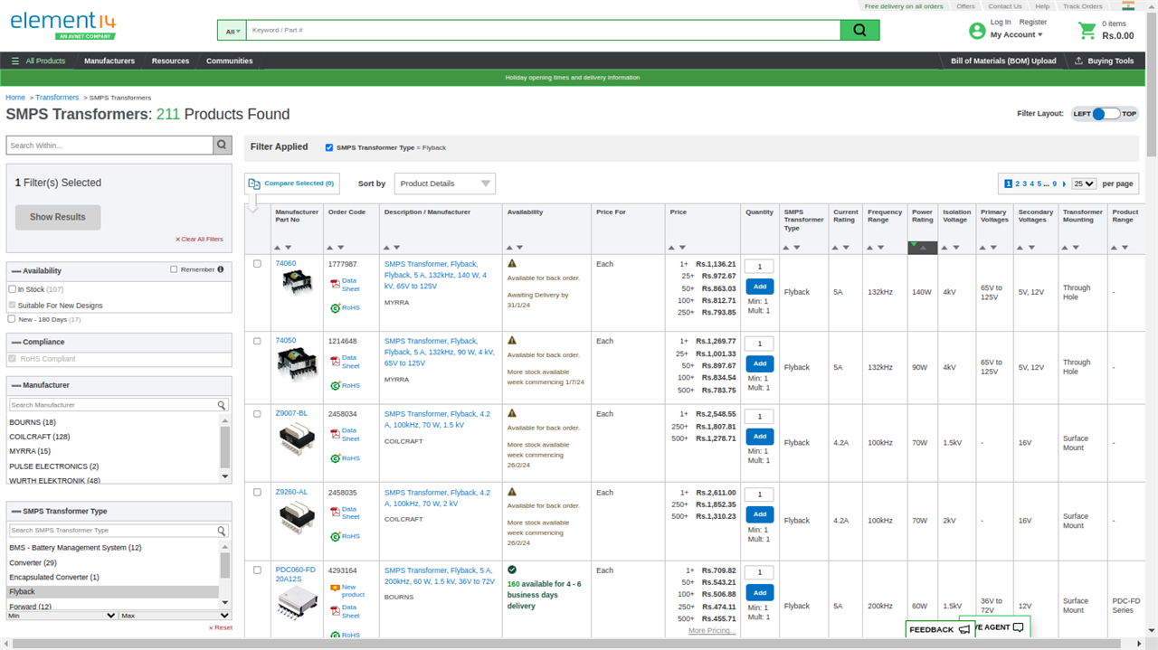
As can be seen the highest wattage is 140W from MYRRA - SMPS Transformer, Flyback, Flyback, 5 A, 132kHz, 140 W, 4 kV, 65V to 125V
2. TVs and Monitors
In today's scenario, TV sets are 4K, thin profile TVs and monitors are LCD. These are even used as signage and display units. Both TV and Monitors, need AC-DC converter ICs and use LLC topology when higher wattages like 220 W or 500W are needed but 65W flyback are also popular in this range, which has input of 85 VAC- 265VAC and output of 20 V, 3.25 A. And these are built on either Flyback topology or Quasi-Resonant (QR) Flyback topology, where 85W can be achieved.
Nowdays, when switched on, the average TV consumes 58.6 watts and 1.3 watts in standby mode.
Here, the same color TV sets which needed 10kV or may be 25 or 35 kV, now requiring 65W- 500W transformers but the 500W transformers are not flyback transformers!
Note : common TVs are generally consume max of 120W for even 65 inch or 86 inch screen.
As mentioned flyback topology is limited to 150W, here in this TV range, the popular is 65W, 85W flyback transformers.
3. Tool & eBike Chargers
The Tool & eBike Chargers need AC- DC conversion and again if 65W or below 150W is needed, then flyback transformer or QR Flyback topology used. For higher wattages, other topologies are used like in ebike 240W adapters are not based on flyback but on LLC and it can be on other topology also.
4. Computers & Servers
Again for below 150W or 120W requirements, flyback transformer or QR Flyback topology is used ; for higher wattages, other topologies are used. The Computers & Servers use AC-DC flyback transformers but Power Over Ethernet (PoE) need DC-DC flyback transformers.
5. LED Driver
The LED Drivers are used for dimmable and non-dimmable applications like integrated LED ceiling fixtures, troffers, downlights, spotlights, track lights, low bay, smart lighting, wireless and wired PWM to wired DALI (Digital Addressable Lighting Interface) connectivity.
For power requirement < 120 W or < 150 W, flyback transformer or QR flyback topologies are used.
6. IoT, Smart Home and Building Automation
IoT, Smart Home and Building Automation even require 0.25W adapters which do no need transformer isolation, for other purposes like smart speakers, tubular motors, wall outlets where power requirement is < 120 W or < 150 W, flyback transformer or QR flyback topologies are used.7. Meters and Industrial Equipment
The Meters and Industrial Equipment like motor control can vary to < 150 W to kW or MW but whereever < 150W is needed, flyback transformer or QR flyback topologies are used.8. USB PD Adapters
II. Topologies & Theory of Operation
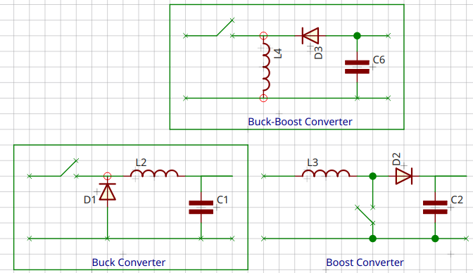
As Flyback is a transformer isolated buck-boost converter, the buck-boost topologies do not end with simple flyback buck-boost. There are variants in buck-boost topologies, and also to add confusion there is also boost-buck topology.
The buck–boost converter is a type of DC-to-DC converter that has an output voltage magnitude that is either greater than or less than the input voltage magnitude. It is equivalent to a flyback converter using a single inductor instead of a transforme
Can all these be called as flyback transformers or flyback converters ?
A. Buck-Boost Topologies
- Buck-Boost
- Flyback
- Non-inverting buck-boost converter
- Inverting buck-boost converter
- Four-switch buck-boost converter
- Zeta Converter (some call Zeta is boost-buck not buck-boost)
- Fly-Buck-boost
- Flyback ZVS
- Flyback Active-clamp
- Flyback CCM
- Flyback DCM
- Flyback Quasi Resonant
- Flyback Non Sync
- ß-Flyback (Self Claimed, not demonstrated neither in simulation nor practically)
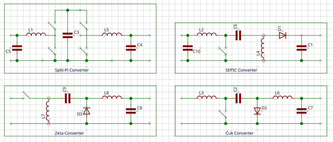
B. Boost-Buck Topologies
- Split-pi topology
- SEPIC and Inverse SEPIC
- Ćuk converter - Non-isolated Ćuk converter ,Isolated Ćuk converter, Coupled inductor isolated Ćuk converter, Integrated magnetics Ćuk converter, Isolated Ćuk converter with gapless AC transformer.
- Zeta Converter
Some call SEPIC, Ćuk as buck-boost instead boost-buck.
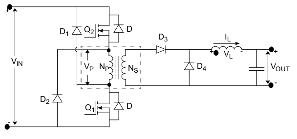
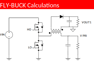
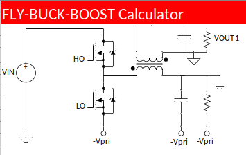
Below is gallery of these toplogies. I have also included forward, two-switch/two-transistor, flybuck, flybuck buck boost, boost-buck, zeta, Split-pi, SEPIC,Ćuk.
| {gallery}Topologies |
|---|
 |
 |
 |
 |
 |
 |
For detailed theory of operation, variations of buck-boost topologies and, pls see my following videos.
Videos
1. Volt-Sec Balance
2. Quadrant Switch Operation
3. Buck
4. Boost
5. Buck- boost
6. Flyback
III. Conclusion
1. Conclusion of Part-B
This is the conclusion of 'Section I, Part- B', where I have mentioned the use of FBTs in today's scenario.
In the 'Part-B', I have presented flyback transformers from different manufacturers with the application use in different industries. I have tried to bring out into notice that in all cases, whether the input is AC or even if DC, the flyback (derived from buck-boost) has been used as strictly step-down. Why I used 'stri1ctly' in step-down because, the output voltages can never be increased than the primary, and moreover, they are voltage or current controlled like PI or PID methods as a regulated power supply. I will make design videos using application notes in blog 3.
Moreover, in the specifications of flyback transformer (whether AC or DC), the primary is having higher voltage rating (fixed) than the secondary and the secondary output voltage is FIXED, to either 1 voltage or 2 voltages or more but they are fixed to lower voltages.
The specifications are not mentioned like this
- Input is 110 VAC, and output is 5 VDC, 120VDC and 350VDC
or as where the input is AC, then

the output voltages are 5VDC but by changing duty ratio, it can be 120VDC or 350VDC.
that is, specifications in all cases, are mentioned like this
The output voltages are 5VDC, 3.3VDC, 12VDC, 15VDC, 24 VDC, which is less than the primary.
- output 1 is 12VDC,
- output 2 is 5 VDC
- output 3 is 3.3 VDC
NOT
- output 1 is 12 VDC,
- output 2 is 120 VDC
- output 3 is 300 VDC
And not even boost like this
- output 1 is 600VDC,
- output 2 is 400 VDC
- output 3 is 500 VDC
Moreover, the output power is LIMITED TO (in case of flyback converter/topology) 120 Watts or max 150W.
If the requirement is more than 150W, other topologies are always used not flyback like for instance if the Tesla car or evehicle/ebike chargers need 1kW or 3.6kW, then the same chargers are based on half bridge or half bridge LLC or full bridge or full bridge with phase shift or multi-resonant like CLLLC DAB (dual active bridge) chargers, but not on flyback topology.
So, this topology is resticted to some Watts, and it can be buck or boost based on the duty ratio BUT like as shown above(like in TI) , it has to be checked whether the transformer and controller can be used only for buck/flyback operations or buck/boost/flyback.
One cannot blindly expect the desired boost output level of his/her desire. There are limitations here and moreover interleaved topologies or 3 stage , 2 stage or 4 stage or 2 phase designs come into play.
2. Answers of Part A
1. Question
My Comment
I am taking your powerline-modems, as meant for power line communication (PLC) modem, not programmable logic controller (PLC) but even if PLC is programmable logic controller, then also, flyback transformers as used.
Neither for powerline-modems nor for programmable logic controller (PLC), flyback transformers are never used as 'energy storage is an asset rather than a liability' (if you mean by this).
Firstly, I take a flyback transformer used for programmable logic controller (PLC). I need not go outside but here on e14, we have another design challenge - Experimenting with Industrial Automation and in the kit description, its mentioned - 'ABLM1A24025 Power Supply' . Below is the screenshot of its specifications
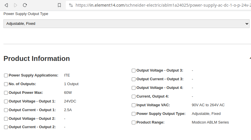
As you can see the input is again AC : 90-264VAC and the output is 60W with 24 VDC, 2.5 A.
As mentioned above in conclusion of Part-B, the flyback topology is the preferred choice for output power requirements < 150 W. So flyback topology is used, but I can design the same Schneider Electric(if given) with LLC or CLLLC topologies, the reason for chosing flyback is shortly revealed.
Now, I take power line communication (PLC) modems.
- Renesas- R9A06G061 Evaluation Kit
- PLC1672 Power Line Communication Module
- PLC-RF Hybrid
-
ST Microelectronics EVALKITST8500-1
Renesas- R9A06G061 Evaluation Kit
This is for both AC and DC power line communication. More specifically
- For DC power line communication, Renesas has CPX4 Evaluation Kit, M01D01, RTK0EE0009D01001BJ
- For AC power line communication, Renesas has CPX4 Evaluation Kit, M02D02, RTK0EE0009D02001BJ
For DC power lines, voltage range is 16V to 48V DC ; and for AC power lines 100V to 230V AC. The AC power line need to be stepped down to rated 15V, 1.2A = 18W.
There are kits from Renesas for PLC, but they all have similar voltage ranges.
PLC1672 Power Line Communication Module
This Power line communication Modem is used for Home Automation, Data Acquisition System, Automatic Meter Reading (AMR) and Lighting Control. Below are its specifications
- Power Supply : DC 12-24 Volt (12 Volt recommended)
- Max current 200ma
- Default Baudrate of 9600.
- Communication in half duplex mode.
- Working environment : 230V 50/60Hz
- Communication distance : 150m
- Power line carrier frequency : 72kHz
As can be seen, again here the input is AC, 230 VAC and the output is 12VDC or 24 VDC.
PLC-RF Hybrid
If now, even if I take hybrid modems or ICs, for PLCs and RF like Renesas R9A06G037(which is RF System on a Chip), this particular is a Narrow Band Power Line Communication modem, and uses communication protocols - G3-PLC Hybrid and PRIME Hybrid.
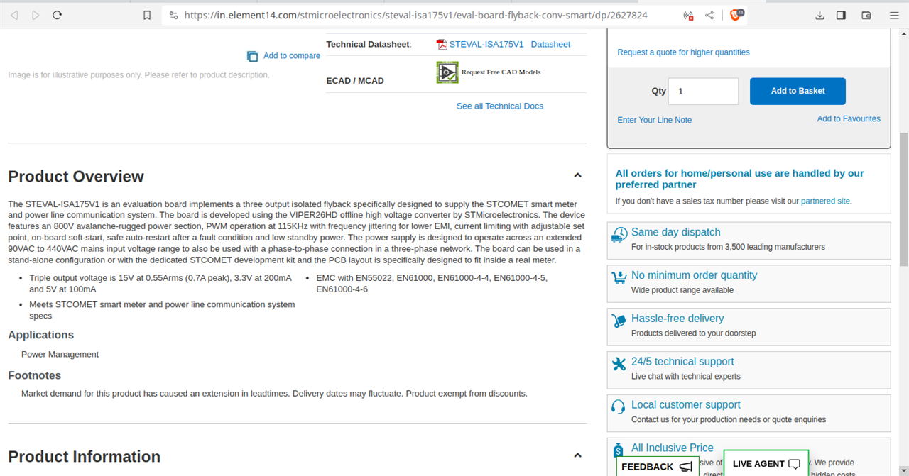
Below are its specifications
Input : 90VAC to 440VAC
Output voltages
- 15V at 0.55Arms (0.7A peak),
- 3.3V at 200mA and
- 5V at 100mA
Wattage : 9.4 W
As I have mentioned in 'Conclusion of Part-B',(in the last point), the flyback transformers are used upto 120 W or 150 W(Max.), the wattage required by power line communication modem is 9.4 W or may be 20W but < 120 W.
Similarly, for programmable logic controller, the output is 60W , again < 120W.
The choice of flyback in PLCs is neither as an energy storage asset nor liability but because
- flyback is the simplest topology
- flyback is the choice used to design any supply < 120W or 150 W, though supplies based on forward converters or other topologies (which I have mentioned in my background) can be used.
- flyback is cost effective, and manufactuer can make profits.
- If the same is designed on other topology, it will increase product cost. If suppose, the charger cost if is USD $ 25, other topology can make the cost USD $35 .
- Other topologies need HIGH engg. knowledge, high R&D cost and such engineers on large scale are not available in the market, as it needs high competancy.
- for flyback, calculators (like one shown of TI) are available from different vendors. This allows that any technician or phd ,even a novice can simply make a supply. For other topologies, one will need to do manual calculations.
2. Flyback is AC- DC or DC-DC
As can be easily seen from blog1 and the above in 'B. Uses in Today's Scenario', flyback transformers are available and come in the market both as AC-DC and DC-DC.
3. Flyback Converter or Flyback Transformer
The transformer is just one piece or component as can be seen in blog 1, 12 transformers are for this contest.
Flyback converter is the whole PCB with many components, doing the conversion based on flyback topology.
4. Terminologies Used
- Flyback, Flyback switcher, flyback offline, off-line flyback switcher - All Same
- Flybuck or Flyback or fly-buck-boost - All Different
- flyback or flyback boost circuits or buck-boost or inverting Fly-Buck-Boost Converter- All Different
- flyback boost is often heard in case of boost voltages needed for CRT.
5. Lets come to FBT CRT which is one of the motivation behind this blog.
1) Lets do some maths based on 150W limitation as in the context of 'power electronics - topology limitations'
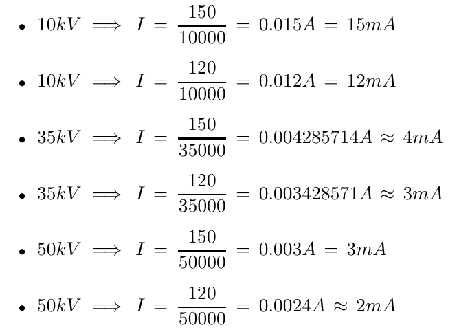
which should be in general case, is completely wrong; as for the limitation to be restricted to 150 W at 10 kV gives max. current of 15 mA, which for 50 kV becomes 2 mA.
But in case of old TVs and monitors, FBT is a high current transformer !, thus, this 150W do not apply in case of flyback boost operation. This can also be seen from above FBT Schematic gallery, I have shown some pins like collector, video , v1, v2, heater etc.
The heater alone draws 0.5A - 2 A of current, which cannot be extracted with this restriction of 120W or 150W flyback (derived from buck boost) as the max. current can be only 2 mA(for 50 kV) and 15 mA(for 10KV).
So, the FLYBACK TRANSFORMER
- In Case of OLD TV/CRT IS NOT DUE TO BUCK-BOOST TOPOLOGY but due to buck & boost operations and a flyback action, shortly explained.
- In Case of Part-B, is DUE to buck-boost topology and a flyback action, shortly explained.
2) The similarities in both FBT applications is related to SMPS, as in both applications
- Both FBTs use switching frequency.
- Whether, FBT for CRT or FBTs limited to 120 or 150W, both are switch mode power supplies (SMPS) because in both the switching frequency can be varied. In the former case, that is, for CRT, FBTs can be switched from about 30 kHz to 150 kHz, but in the latter case, FBTs can be switched from 8 kHz to upto 2 MHz but generally are switched upto 700 kHz.
- Both generate high-voltage sawtooth signals at a relatively high frequency.
- The very high voltages are easily obtained using relatively few turns of windings due to flyback action or flyback topology philosophy
3) In case of Part- B like applications, the circuitry of FBT is derived - buck topology followed by boost topology (as in video), which makes a transformer isolated buck-boost.
Now, question left is of flyback action
As I have mentioned in the video, during the TON period,transformer behaves as an inductor, and this flyback transformer is at this time of operation is not FBT but now is an inductor which stores energy in its magnetic field and during TOFF period, this stored energy stored in the magnetic field of inductor or the primary of FBT is transfers to secondary through the flyback action.
4) In case of CRT, as I have claimed and said, the flyback is not due to buck-boost topology but due to buck & boost operations and flyback action
- buck-boost topology is declined due to 2 mA or 15 mA maximum restiction
- buck & boost operations-
As I have just mentioned there are pins, and shown in FBT schematic, you can see in pins these supply 24 V, 16 V, 180V, 45V
, and the input supply is 230VAC or 120VAC,
- so these are simply buck for 24V, 16V, 45V, 1.4V, 6.3V from 230VAC or 120VAC,
- and as CRT is fed with 10 kV or 25 kV or 35 kV or 50 KV is a boost.
- flyback action
Here the flyback action is not due to energy strored which is flyback to secondary but
These 10 kV or 25 kV or 35 kV or 50 KV could be easily called as boost, as they boost voltage and generate this much high level of voltage which is connected to CRT (as shown in FBT arc gallery) to three electron beams of RGB to produce image, using this very strong magnetic fields.
These may be sometimes referred as flyback boost but are popular as flyback transformers. THIS is not due to any dependency on buck-boost TOPOLOGY as here the desired output is boost only and one would never want to get a buck voltage on EHT(extra high tension) from these FBTs
whereas on the LOW tension, buck operation is used to get 1.4 V for tubes or 6.3 V from ACinput (230 VAC or 120 VAC)
The reason, these are called as flyback is again due to flyback action and here as I have just said, its connected to CRT/picture tube. In this CRT/picture tube, the front area of the tube is scanned repeatedly, and an image is produced by controlling the intensity of each of three electron RGB beams.
There is a horizontal movement of the electron beam in CRT,
AND THE BEAM FLEW BACK OR THE BEAM FLY BACKS, TO BEGIN THE NEXT HORIZONTAL LINE.
and this is principal operation of the working of a CRT whether TV set or color tv or old computer monitor or crt oscilloscope.
without this continuos flyback of the beam, the image or the waveform could not be seen, and HENCE, these were popular as flyback transformers.


