


In the previous blog I mentioned we were going to take a quick look at calculating common mode filters. Unfortunately, we're going to have to skip that bit for now as I was unable to get a complete understanding of how to design common mode filters, and don't feel comfortable just mindlessly pasting formulas and parroting them back at you, so instead, we'll take a look at the non-flyback components included in the kit and perform some experiments with them.
Common mode chokes, what are they?
In simple terms, common mode chokes are 1:1 transformers. They are used as the main component in common mode filters to reduce noise, usually from the power rails of switched mode power supplies. As covered in the previous blog, we saw that ringing and switching noise not only affected the components of the flyback converter, but it also leaked to the rails, both on the 5 volt rail at its input and the output.
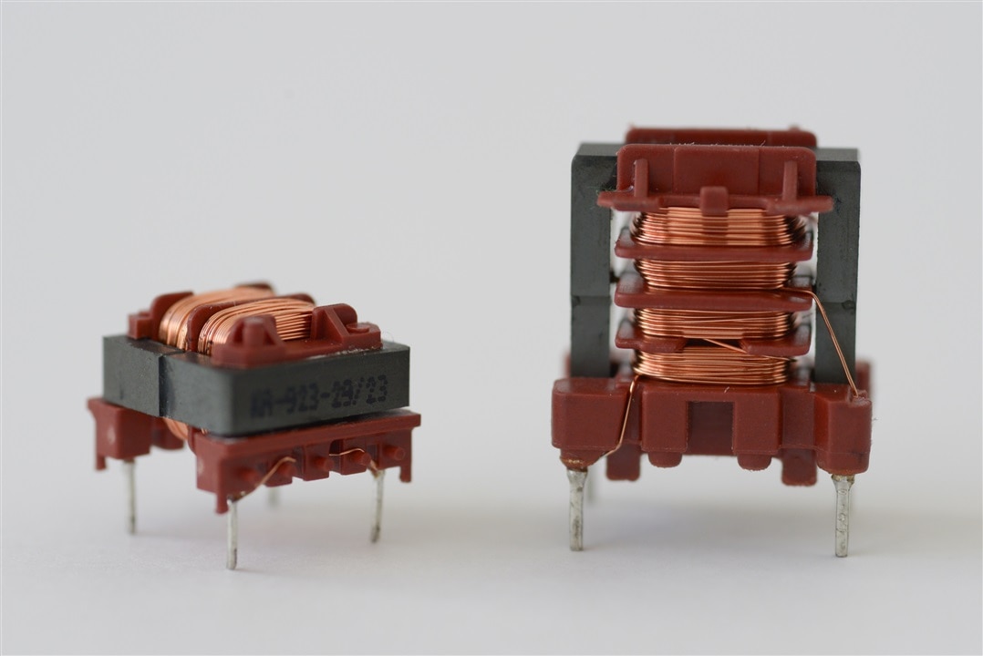
The two common mode chokes provided with the kit are the
071923 and 093267
These chokes are designed for use with the Smart Power Transformers. Bourns claims these chokes are good for both common and differential mode noise filtering, and since that should be the case with most EMC filter chokes, it's not a questionable claim.
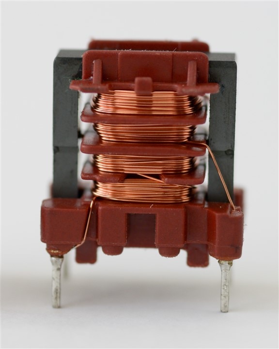
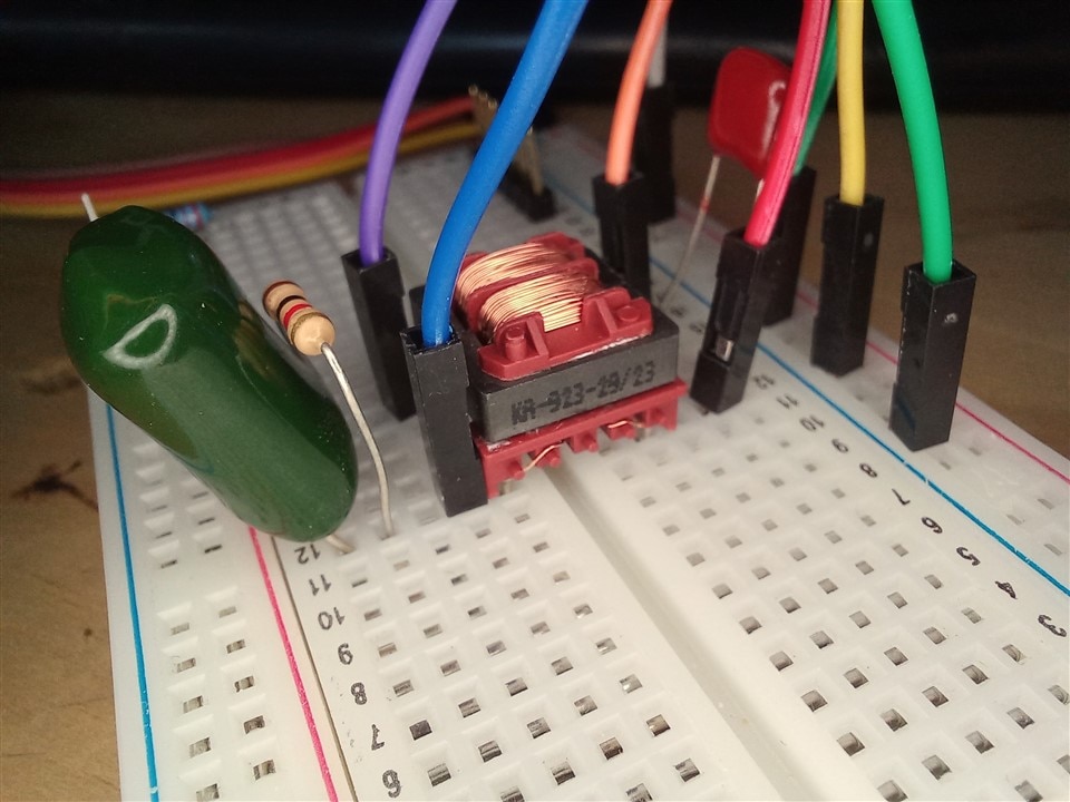
At a glance, they are very similar, electrically speaking, but as you saw in the picture above, they are quite different in terms of their construction.
Let's look at the
071923
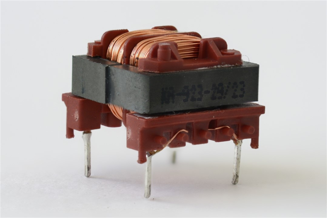
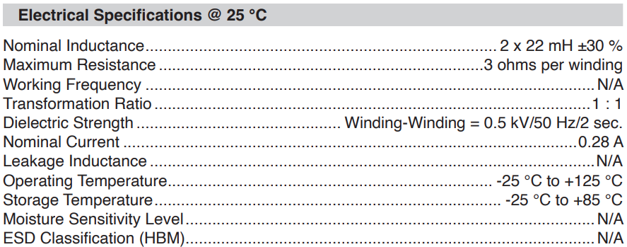
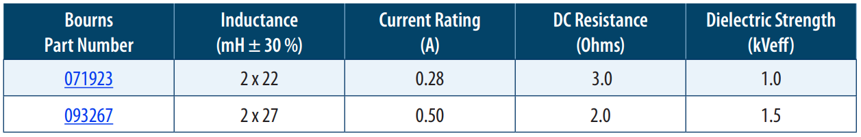
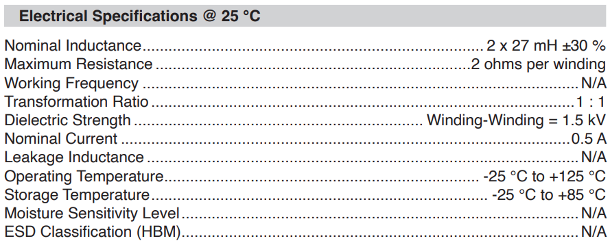
Looking at its dielectric strength specification, we see it differs from what's mentioned in the new product release file and claims 0.5kV instead of1kV
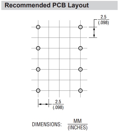
It comes with a standard 2.54mm pin pitch, so we can place it in a breadboard for some quick prototyping
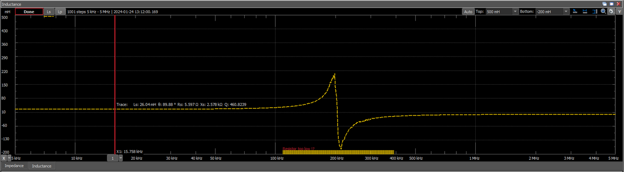
I quickly measured it with the AD2, and it read just under 21mH for most of the frequency sweep, so I'm not sure why they specify +/-30% tolerance.
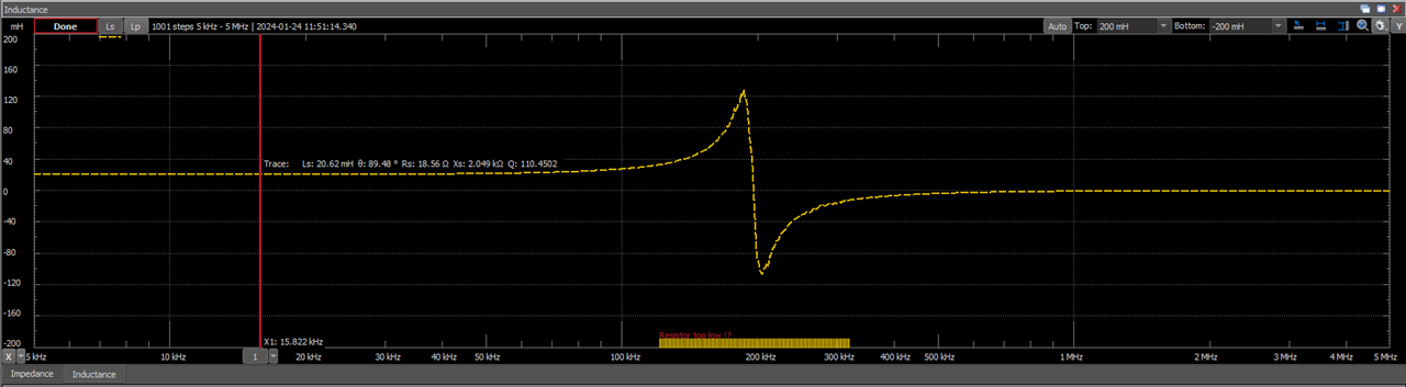
poking it with the multimeter reads 2.9 ohms, which is pretty much the 3 ohms specified.
Now let's look at the
093267
This one does agree with the new product release specification with a dielectric strength of 1.5kV
Its pin pitch is 2.5mm, so it will still fit into a standard breadboard, with just minor persuasion.
Running it through the AD2, it also reads well within spec, and I again wonder why they specify +/-30% for these chokes. That seems unreasonable, maybe they meant +/-3%? hmmm!
Now is time for some...
Common mode experimentation
This introduction to EMI suppression filters by Murata tells us about the kinds of noise we can expect to encounter and includes a section on common mode noise on differential signals.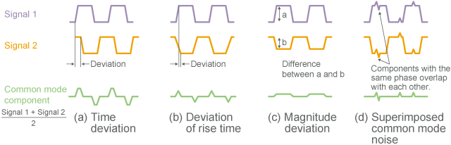
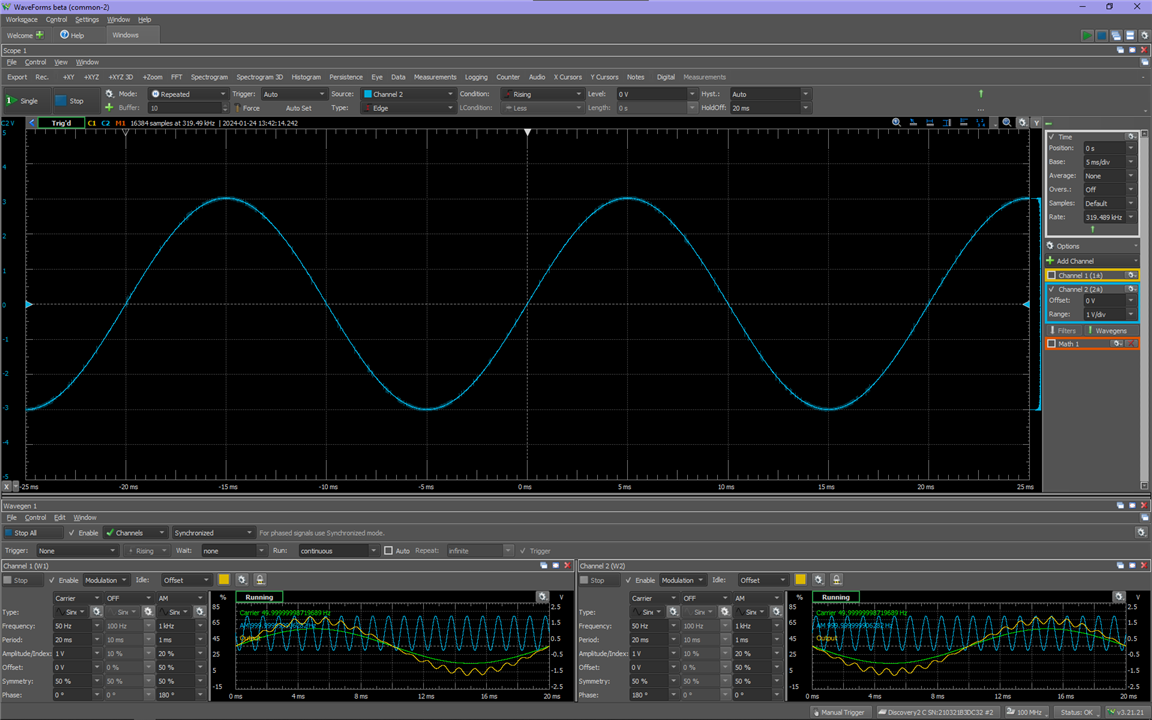
Using that image from their guide as a reference, I set up a differential signal on the AD2's waveform generator and added a common mode higher frequency sinewave on top of it like this:
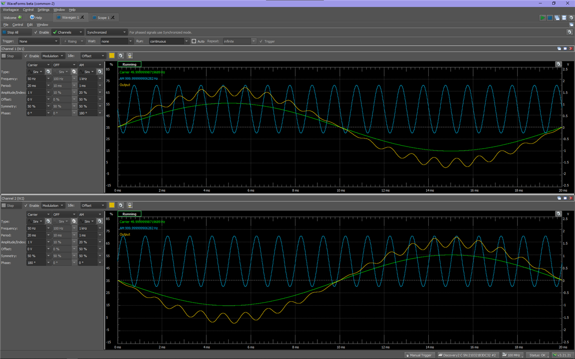
and using a math channel on the scope, I can extract the common mode noise:
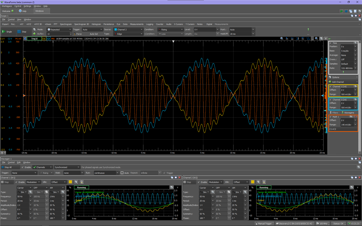
You can see the superimposed higher frequency signal is in phase on both channels.
If we then probe with one channel of the oscilloscope both wavegen outputs, we can confirm how much of that signal is common mode and how much of it is differential. Since the higher frequency signal is symmetric, we would expect to see no noise on the oscilloscope when probing like that, and that's exactly what we observe:
Now see what happens as i slowly change the symmetry of the higher frequency signal:
We can't see the common mode noise if we differentially probe our signal of interest, so as i make the higher frequency signal less symmetric, the differential portion of it shows up when probing across channel 1 and channel 2.
Let's now see what happens when we look at the signal with the previous setup (oscilloscope channel 1 probing across generator channel 1 and ground, and oscilloscope channel 2, probing across generator channel 2 and ground) and also change the symmetry:
The common mode amplitude changes as the symmetry changes, but it never goes away.
Now that we see how common mode signals behave, let's try to filter them out.
I built this circuit with random components just to see how it would behave as I increased the common mode signal's frequency:
It is connected as shown in this diagram:
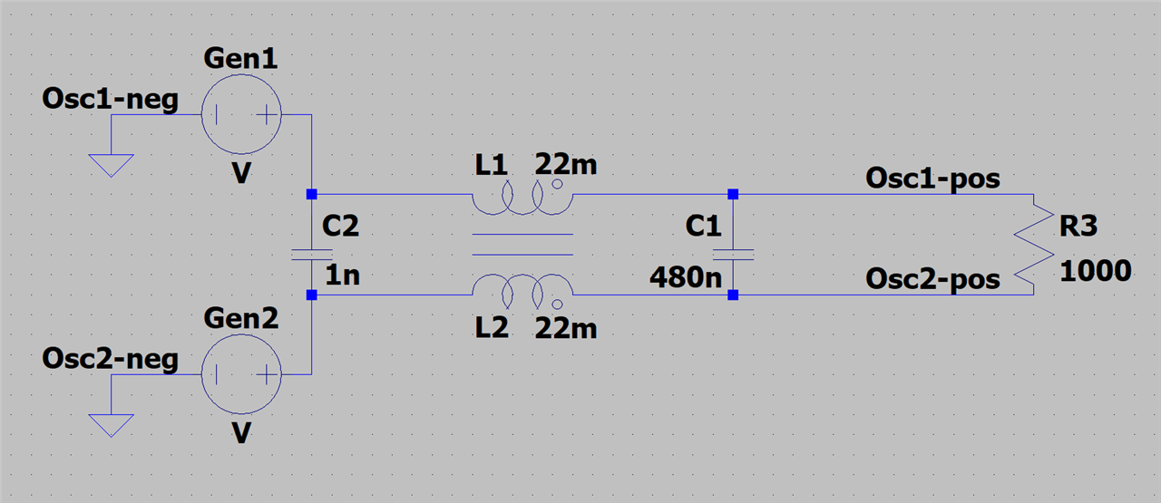
This is its behaviour as the common mode signal's frequency increases:
We see that at the load the common mode signal begins to be attenuated at around 150KHz and up to about 500KHz, so the filter is doing something. It's interesting that the signal grows larger at around 100KHz, but from the measurement of the choke, we saw that around there it approaches its self-resonance frequency, so that might be what's causing the signal to jump up at those frequencies.
Now let's look at the common mode signal at the filter's input, to see if anything looks different there:
It's clear that at the input the signal isn't being attenuated. You can see the common mode signal changing in amplitude in orange, but that's how the AD2 handles high frequency sisgnals at a slower timebase. You can notice the amplitude remains the same if you look at the semi-transparent parts of channel 1 and channel 2 as the frequency of the common mode signal goes up. This means the filter is indeed working!
One thing to consider is that the noise needs to go somewhere, and since it's common, it's referenced to ground. You may have seen an EMI filter showing X and Y capacitors connected like this :
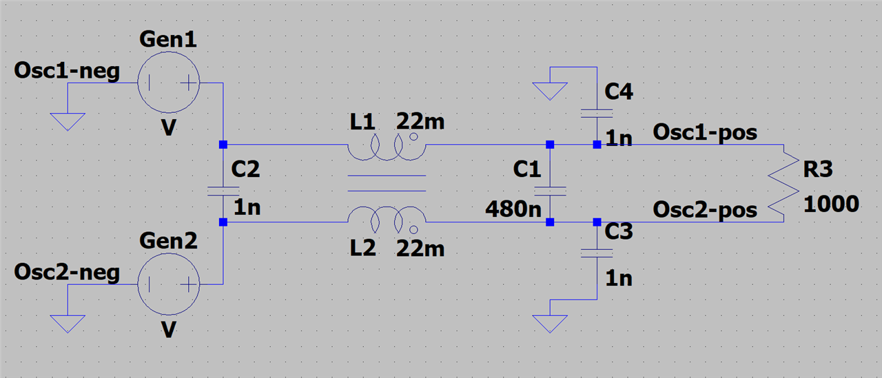
C3 and C4 are the Y capacitors, while C1 and C2 are the X capacitors. The Y capacitors provide the common mode signal with a path to ground.
I built that circuit:

and tried again to see what happened with the common mode signal:
We now observe the increase in amplitude at a much lower frequency, starting at about 20KHz, but now the attenuation at 100+KHz is much better than before.
There is a lot more involved in the design of EMI filters than getting a choke and throwing random capacitors at it. I just demonstrated the working principle of the common mode filter topology, but for those interested in delving deeper into the topic, I would recommed this OMICRON Lab playlist: EMC Filter Design Lectures by Dr. Ali Shirsavar. That should be enough to get you started.
Now that we saw common mode filters in action, it's time to take a look at the
Gate Driver Transformers
Bourns Included in the kit a pair of of Power Line Communications transformers. While these transformers are not explicitly advertised as gate driver transformers, as they are designed for signal transmission, they would be well-suited to handle the PWM signal to switch the MOSFET.
First we have the
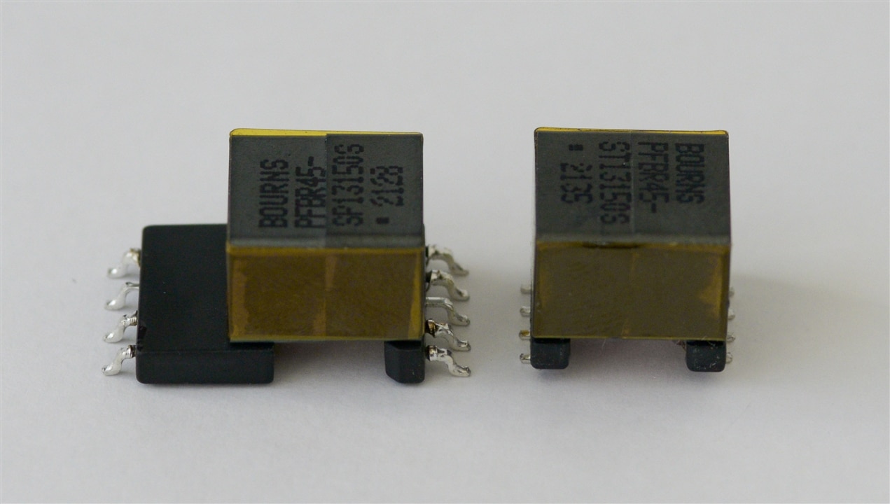
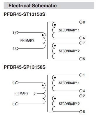
PFBR45-ST13150S
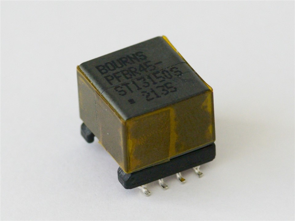
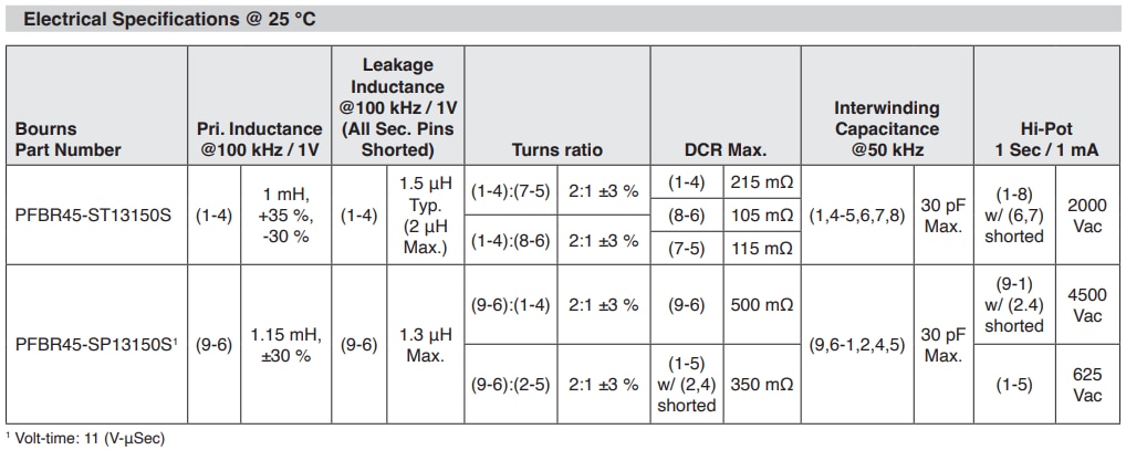
This transformer has a nominal primary inductance of 1mH. It has two secondary windings, and the turns ratio between the primary and each of the secondaries is 2:1. Curiously one of the windings has a slightly higher DC resistance at 115mΩ compared to the other secondary's 105mΩ. It is very similar to its sibling, the...
PFBR45-SP13150S
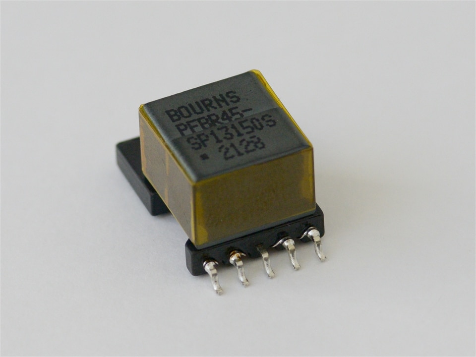
This transformer also has 3 windings, with a nominal inductance of 1.15mH and a turns ratio of 2:1 (primary:secondary) While very similar to its sibling, It has a different physical construction, which bourns calls "Special EP13". Its primary winding has the pins protruding away from the core, and this together with a different insulation on the wire that makes up the winding make it better suited for when more robust isolation methods are needed.
They share a datasheet:
Unfortunately, due to time constraints, I was unable to test them.
The next blog, while less experimental might be a more enjoyable read. There I will select the best transformer for my application, to build a converter around it and bring that application to life.
And in the near future, I'll be revamping this blog to give these parts better coverage for those who might come across the series wanting to learn.
As always, feedback is welcome.
Thank you! 