


After some rather anti-climactic abuse and safety tests which put me at ease, I decided it was time to fly even before I could walk so to speak … in the name of flybacks. After all, I got a late start to this challenge and time is running out, meaning that I’m on a roughly one-blog-a-day timeline to the end. Let’s see what this attempt at a quick win yields … will it be success or failure?
Looking for a Quick Win
It’s a fact that designing even a conceptually “simple” flyback transformer-based converter is complicated if you want to actually get it to work in the way it was intended. The transformers provided are mostly designed for “offline” converters which run off rectified mains. Such voltages can be lethal and I’m not as experienced with it as I would like to carry out a design from the ground up. A mistake could lead to rather loud and explosive results! Another key consideration is that I don’t have the parts at my fingertips to design and build one given the limited time remaining.
As a result, I thought it was a better approach to look for a quick win by modifying an existing design to use a Bourns SP-E flyback transformer instead.
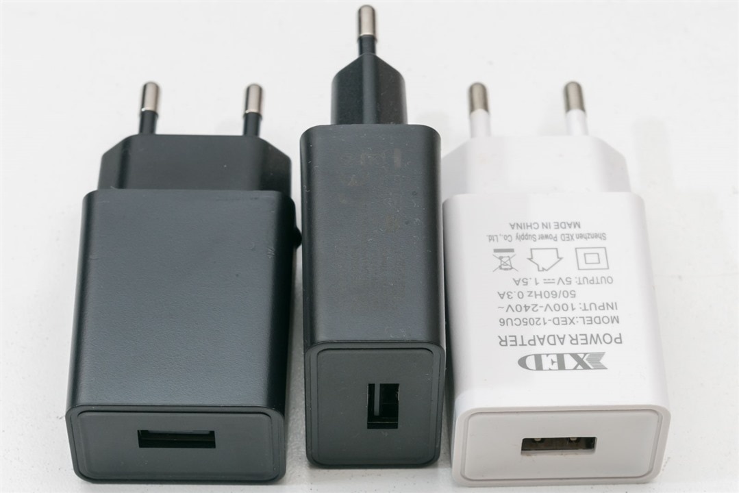
Enter this [insert collective noun] of rather unloved USB chargers. They’re not particularly fast, nor are they trustworthy, coming from random Chinese manufacturers included as “bundle-ins” with bargain-basement priced surveillance cameras, tablets and other novelty items. I wouldn’t trust them with anything precious, so I’ve never actually made use of them, not least because they come with Europlugs which are not used in Australia and are horrible to adapt (as adapters frequently slip on their circular pins). As they’re not going to be used anyway, I’ll just take them apart and see if I have any luck.
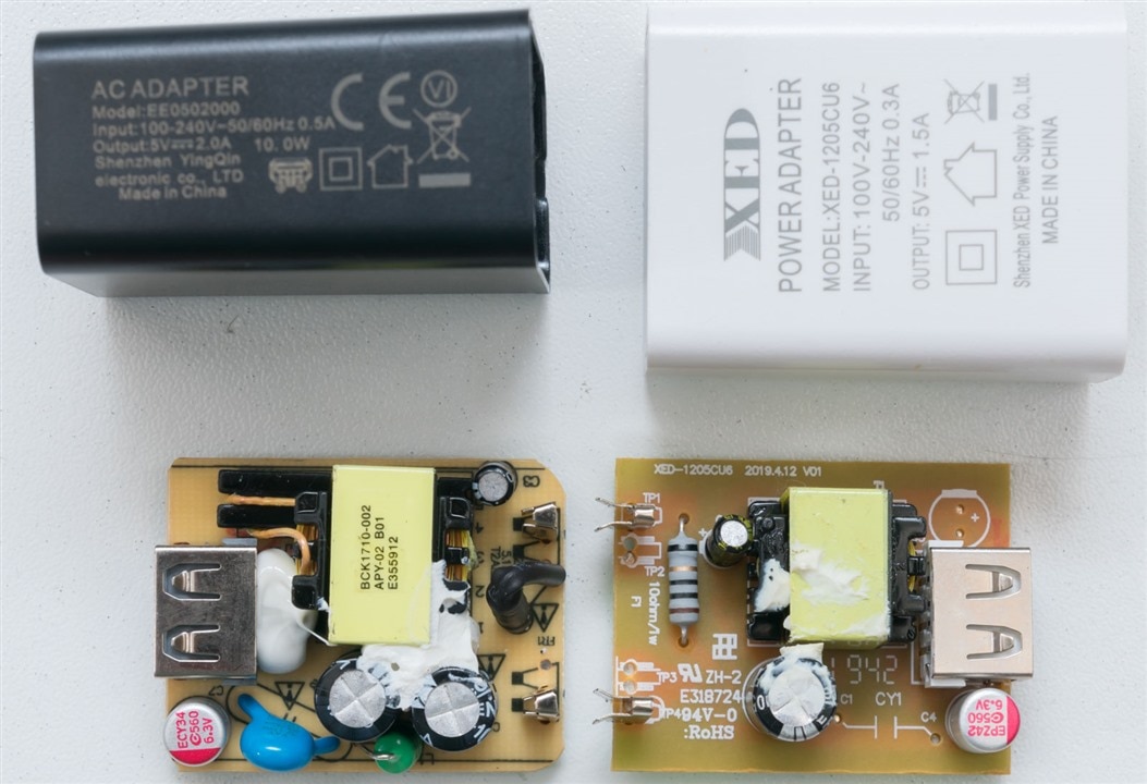
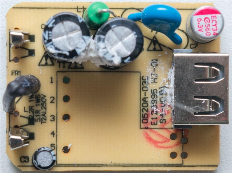
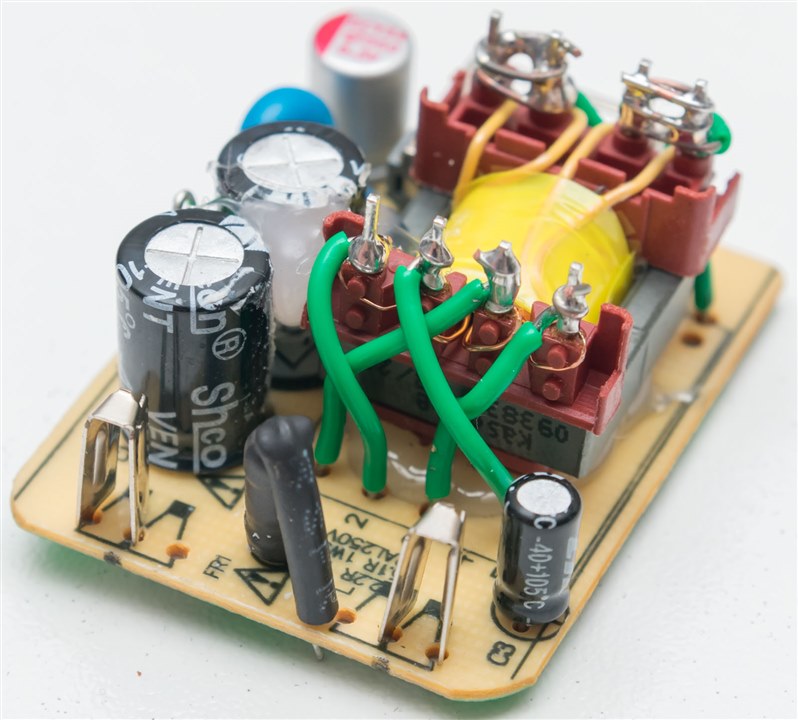
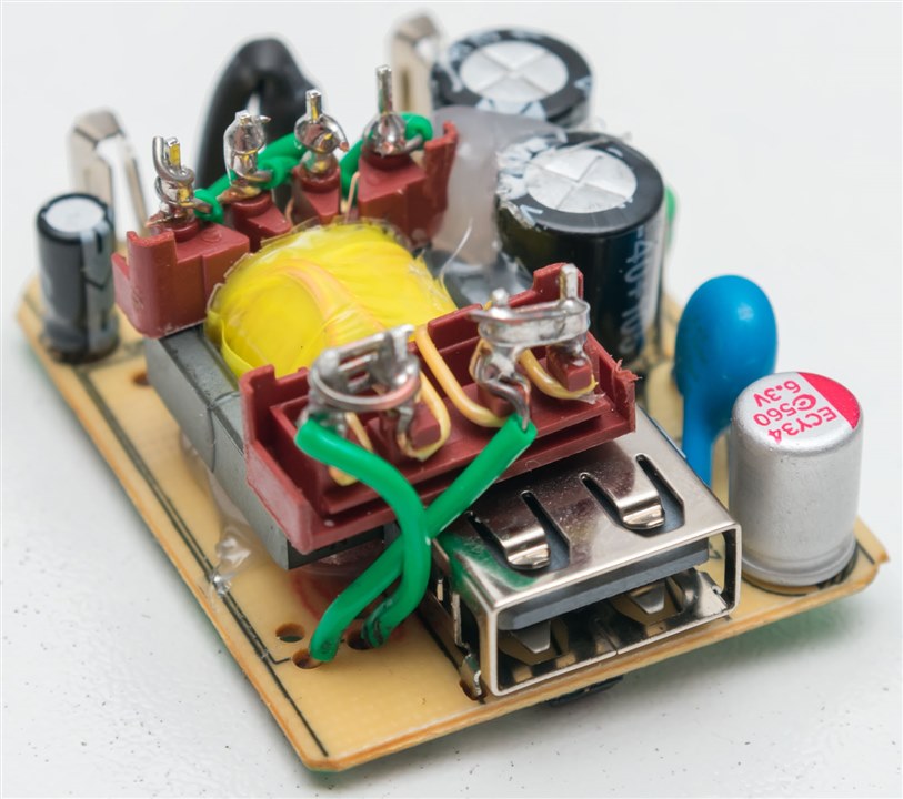
Of the three, there are two different designs. This points to the deceptive nature of some Chinese products – they may share the same external moulding, but internally, they are completely different. I would say the left design looks a little better than the right, but both are very similar, using single-sided paper-type PCBs and a fusible resistor as their protective element.
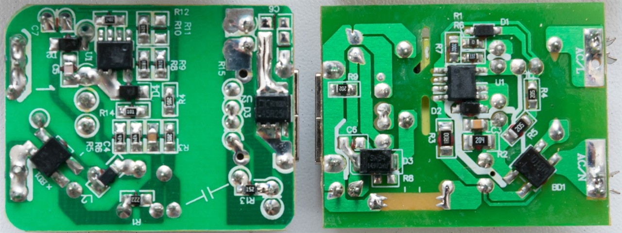
From the underside, we can see both use a mystery chip (likely the same one) as their flyback controller, and both use primary side sensing with no feedback from the secondary. This latter point is a bit of a downside as it might make it difficult to substitute as matching transformer specifications will probably be more critical.
Nothing ventured, nothing gained, so let’s try …
Measuring the Existing Transformer, Looking for a Match
My first instinct was to try and work out what chip is being used so we can get some hints from a datasheet about how to configure the chip.
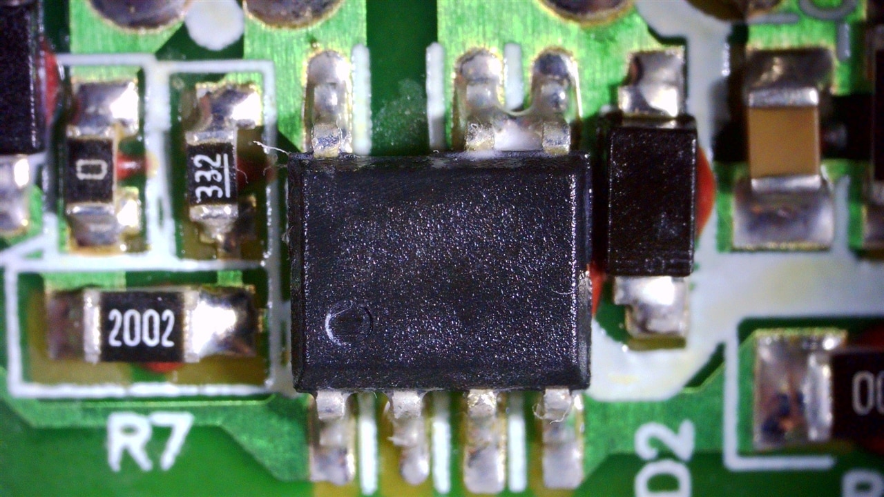
On the first board, we can see the chip markings are impossible to read under the microscope even with the thermal paste trick (some of it has stayed stuck to the pins). Nevertheless, it’s an SO-7 package (one leg missing of the SO-8 for high-voltage clearance) which is one hint.
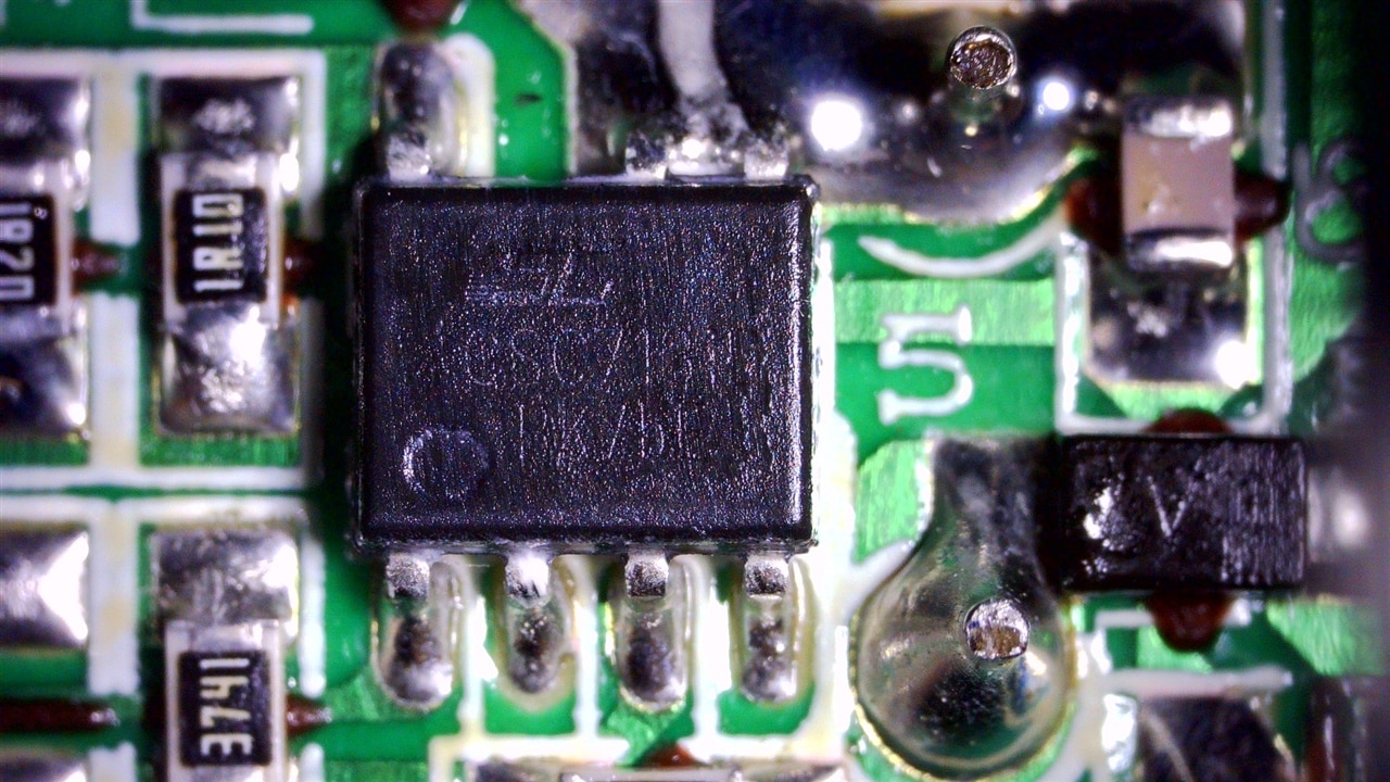
Looking at the other, I think I can barely make out CSC7181D, but it could just be my imagination. I can’t find anything based on the numbers – comparing it to common chips like the SC1161/1162, NCP1247-D and UCC28911 were no match. Maybe it is an AL1692K clone, but I’m not sure as in both, it seems Pin 2 is N/C. No matter what it is, it’s pretty ubiquitous in Chinese products it would seem.
If I can’t find out more about the chip, perhaps the answer is just to remove the transformer and test it.
Out came the desoldering braid and being single-sided, the transformer popped out with no fuss. Doing the same with the B&K Precision BA6010 Battery Analyser and Rohde & Schwarz MXO4 Oscilloscope, I was able to deduce the pin-out, measure the inductances, winding order and winding ratios.
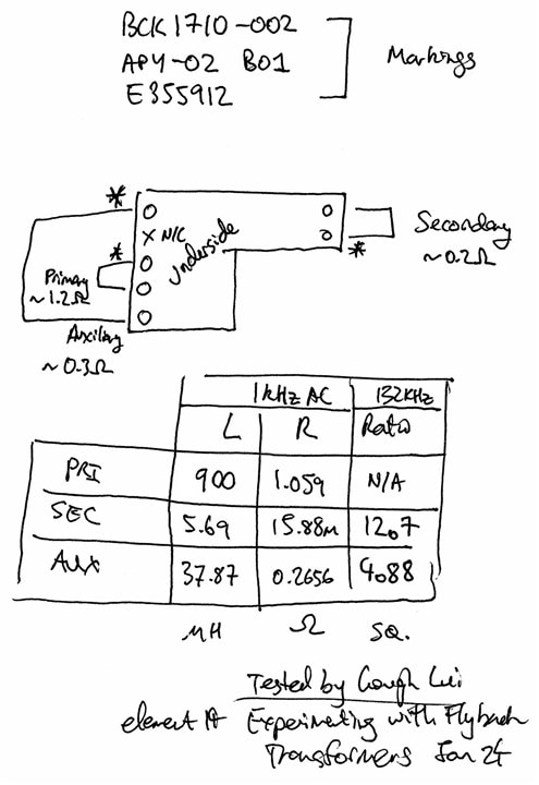
Given that this was for a 5V/2A power supply, or 10W roughly, this already rules out the use of the 063929 and 063932 in the kit (not to mention that they were destroyed in the previous part). Looking at the remainder, I would say the 093830 rated at 8W is probably the closest match – it has a secondary ratio of 18.5 compared to 12.7 which would probably mean slightly lower voltage than expected. The auxiliary winding would be substituted with the shield winding which has a ratio of 4 compared to 4.88. Numerically this may seem close but percentage-wise, it is significant.
But compared to my other options, it is much closer. For example, the 094931 has an auxiliary ratio of 2.75 which is too low, 094932 and 094929 doesn’t have anything resembling the right auxiliary ratio at 1 and 1.1 respectively and 063934 has a ratio of 9.6 for secondary which is perhaps too small (but would have perhaps been my next candidate). I can begin to understand why custom-wound transformers are necessary!
The Result
The transformer itself isn’t a drop-in replacement due to the shape and pin-spacing, so some creativity is required.
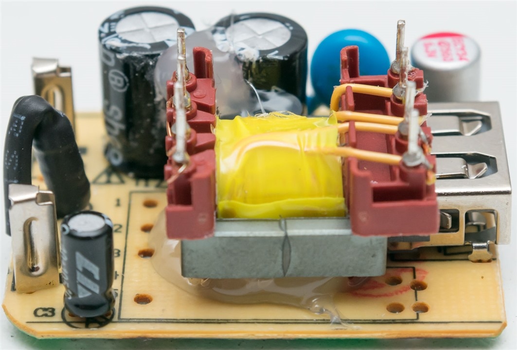
For this rather temporary test, I have used hot glue to secure the transformer “dead-bug” style, upside down. Do not try this at home – it is likely that the transformer may get hot enough during operation to melt the hot glue leaving the transformer unrestrained. Only trained professionals (or trained professional hacks) should attempt this!
From there, using insulated wire, I would wrap around each terminal and solder it, linking using the wire to the PCB to match the required winding order.
The secondary side has both secondary output coils paralleled together in the correct winding order to produce one output of twice the current rating. This is still perhaps slightly less than the original adapter is rated for – but I’d be happy if it just works.
Finally, because it will not fit in its original casing and hence not be able to use its original “pin” contact connections, I found some scrap mains lead from my parts bin and soldered it to the lugs …
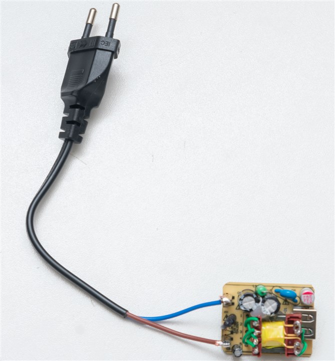
Oh, look. It’s also a Europlug. I have no love for these, but for a temporary test with a plug adapter, that will do. The moment of truth has arrived … so I place the unit into a glass jar with the wires led through the lid just in case it pops, powered through a DC-AC inverter with a very limited power rating …
All that work and … another anticlimax! This time, the unit tries to come up but obviously trips some protection or fault on the way on, shuts down and tries again. It doesn’t matter what the connected load is doing, it won’t fire up. Is it the higher primary inductance? Or the fact the ratios are all different now? Or something else entirely? Unfortunately, I don’t know … but what I do know is that it doesn’t work and perhaps if this had been an optoisolator feedback type circuit, I might have had a better chance.
Testing the PLC Transformers
Well, that was a little underwhelming. To console myself and to make sure the PLC transformers get a test, I decided to whip out the soldering iron to get them mounted onto Veroboard so that I could more easily make connections to them.
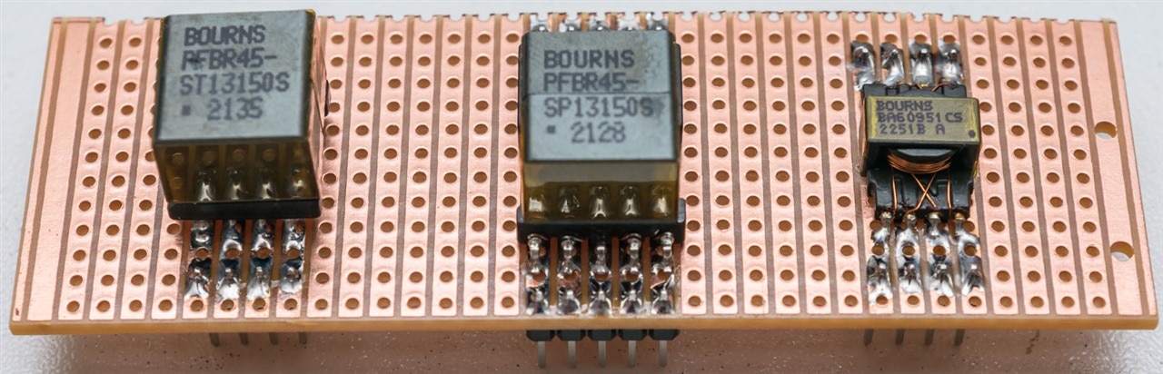
The standard PLC transformer had 2.54mm spacing between legs, making things easy, while the reinforced insulation version has slightly different spacing on the other side. The tiny automotive BA60951CS flyback also has different spacing, but one can kludge them onto 2.54mm Veroboard given some careful alignment.
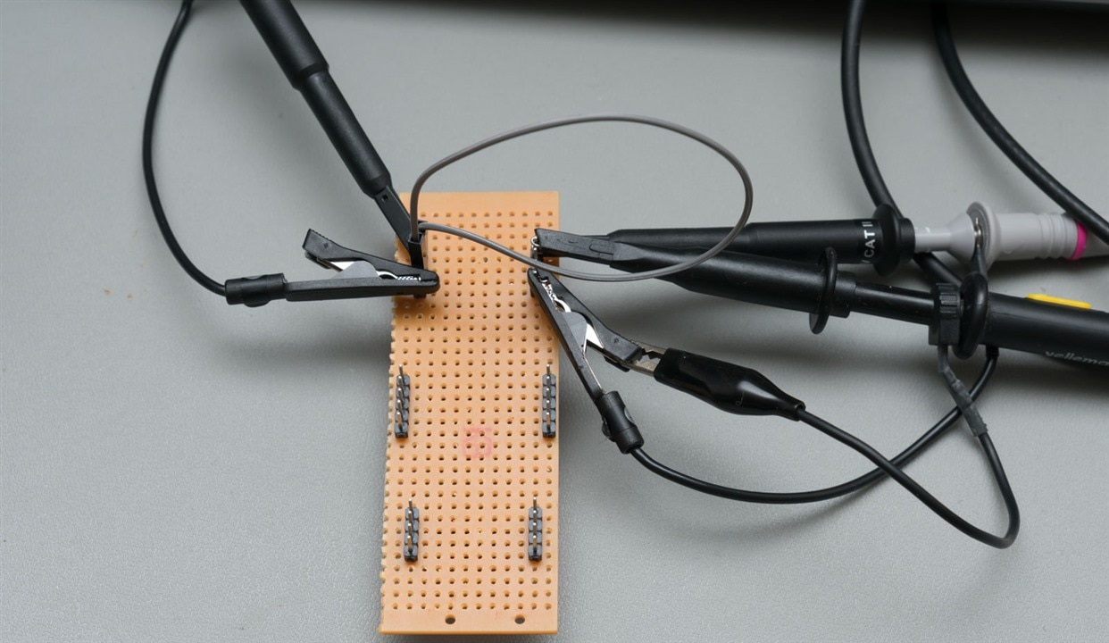
In spite of the better access to the transformer pins for testing, I still had to use clip ground leads which are nasty when it comes to high frequency stuff.
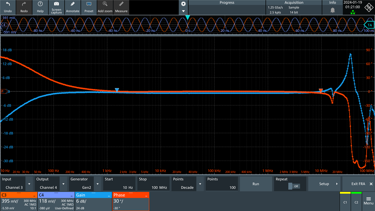
Testing of the ordinary PLC transformer (PFBR45-ST13150S) showed an excellent flat bandwidth response across a range of frequencies starting at around 45Hz (-3dB) and extending past 10MHz. Above there, the mess that is visible is likely due to the clip grounds.
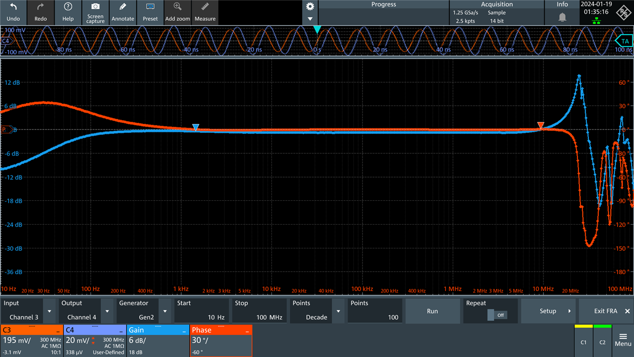
Testing of the reinforced insulation PLC transformer (PFBR45-SP13150S) showed a nearly identically flat frequency response. This indicates good signal integrity for the wide bandwidth of HF carriers commonly used in Ethernet over Power and other PLC technologies.
Conclusion
It would seem that this challenge has been anti-climax after anti-climax. Being under a time-crunch, I thought I’d go for a quick win and try to “fly” (pun intended) when I can’t even “walk” (so to speak) by modifying a cheap, Chinese USB power supply with a Bourns transformer of the closest specification. Unfortunately, all I got was a power supply that kept cycling and trying to come up, likely tripping some protection, but as I don’t know the identity of the controller and how it is configured, there isn’t much I could do. Perhaps this was a bad idea from the start, as this design is a primary-side sensing circuit with no feedback, thus is perhaps more critical of transformer parameters in terms of ratio and inductances. In trying to avoid potential delays and disasters from designing my own mains flyback converter, I’ve learned that close-enough may not be good-enough and perhaps this is why custom transformer designs are necessary for some applications.
In the meantime, I have managed to creatively solder the PLC transformers and the BA60951CS to a piece of Veroboard to make it easier to test – those PLC transformers have pretty flat transfer functions across a wide range of frequencies, but the use of spring grounds in the test does distort their high-frequency results.
In the end, it seems I will have to go back to basics and once I have learned to walk, then I can finally do the walk of shame … in the next post, perhaps. Until then, I shall lick my wounds ...
Top Comments