element14 Community
element14 Community
    Register Log In
  • Site
  • Search
  • Log In Register
  • About Us
  • Community Hub
    Community Hub
    • What's New on element14
    • Feedback and Support
    • Benefits of Membership
    • Personal Blogs
    • Members Area
    • Achievement Levels
  • Learn
    Learn
    • Ask an Expert
    • eBooks
    • element14 presents
    • Learning Center
    • Tech Spotlight
    • STEM Academy
    • Webinars, Training and Events
    • Learning Groups
  • Technologies
    Technologies
    • 3D Printing
    • FPGA
    • Industrial Automation
    • Internet of Things
    • Power & Energy
    • Sensors
    • Technology Groups
  • Challenges & Projects
    Challenges & Projects
    • Design Challenges
    • element14 presents Projects
    • Project14
    • Arduino Projects
    • Raspberry Pi Projects
    • Project Groups
  • Products
    Products
    • Arduino
    • Avnet Boards Community
    • Dev Tools
    • Manufacturers
    • Multicomp Pro
    • Product Groups
    • Raspberry Pi
    • RoadTests & Reviews
  • Store
    Store
    • Visit Your Store
    • Choose another store...
      • Europe
      •  Austria (German)
      •  Belgium (Dutch, French)
      •  Bulgaria (Bulgarian)
      •  Czech Republic (Czech)
      •  Denmark (Danish)
      •  Estonia (Estonian)
      •  Finland (Finnish)
      •  France (French)
      •  Germany (German)
      •  Hungary (Hungarian)
      •  Ireland
      •  Israel
      •  Italy (Italian)
      •  Latvia (Latvian)
      •  
      •  Lithuania (Lithuanian)
      •  Netherlands (Dutch)
      •  Norway (Norwegian)
      •  Poland (Polish)
      •  Portugal (Portuguese)
      •  Romania (Romanian)
      •  Russia (Russian)
      •  Slovakia (Slovak)
      •  Slovenia (Slovenian)
      •  Spain (Spanish)
      •  Sweden (Swedish)
      •  Switzerland(German, French)
      •  Turkey (Turkish)
      •  United Kingdom
      • Asia Pacific
      •  Australia
      •  China
      •  Hong Kong
      •  India
      •  Korea (Korean)
      •  Malaysia
      •  New Zealand
      •  Philippines
      •  Singapore
      •  Taiwan
      •  Thailand (Thai)
      • Americas
      •  Brazil (Portuguese)
      •  Canada
      •  Mexico (Spanish)
      •  United States
      Can't find the country/region you're looking for? Visit our export site or find a local distributor.
  • Translate
  • Profile
  • Settings
Experimenting with Gesture Sensors
  • Challenges & Projects
  • Design Challenges
  • Experimenting with Gesture Sensors
  • More
  • Cancel
Experimenting with Gesture Sensors
Forum Establishing serial communication over UART instead of USB in MAX25405 EVKIT
  • Challenge Blog
  • Forum
  • Documents
  • Files
  • Members
  • Mentions
  • Sub-Groups
  • Tags
  • More
  • Cancel
  • New
Join Experimenting with Gesture Sensors to participate - click to join for free!
Actions
  • Share
  • More
  • Cancel
Forum Thread Details
  • Replies 89 replies
  • Subscribers 41 subscribers
  • Views 10350 views
  • Users 0 members are here
  • MAX25405
  • gesture sensors
  • maxim integrated
  • uart
  • max32620fthr
Related

Establishing serial communication over UART instead of USB in MAX25405 EVKIT

rsjawale24
rsjawale24 over 2 years ago

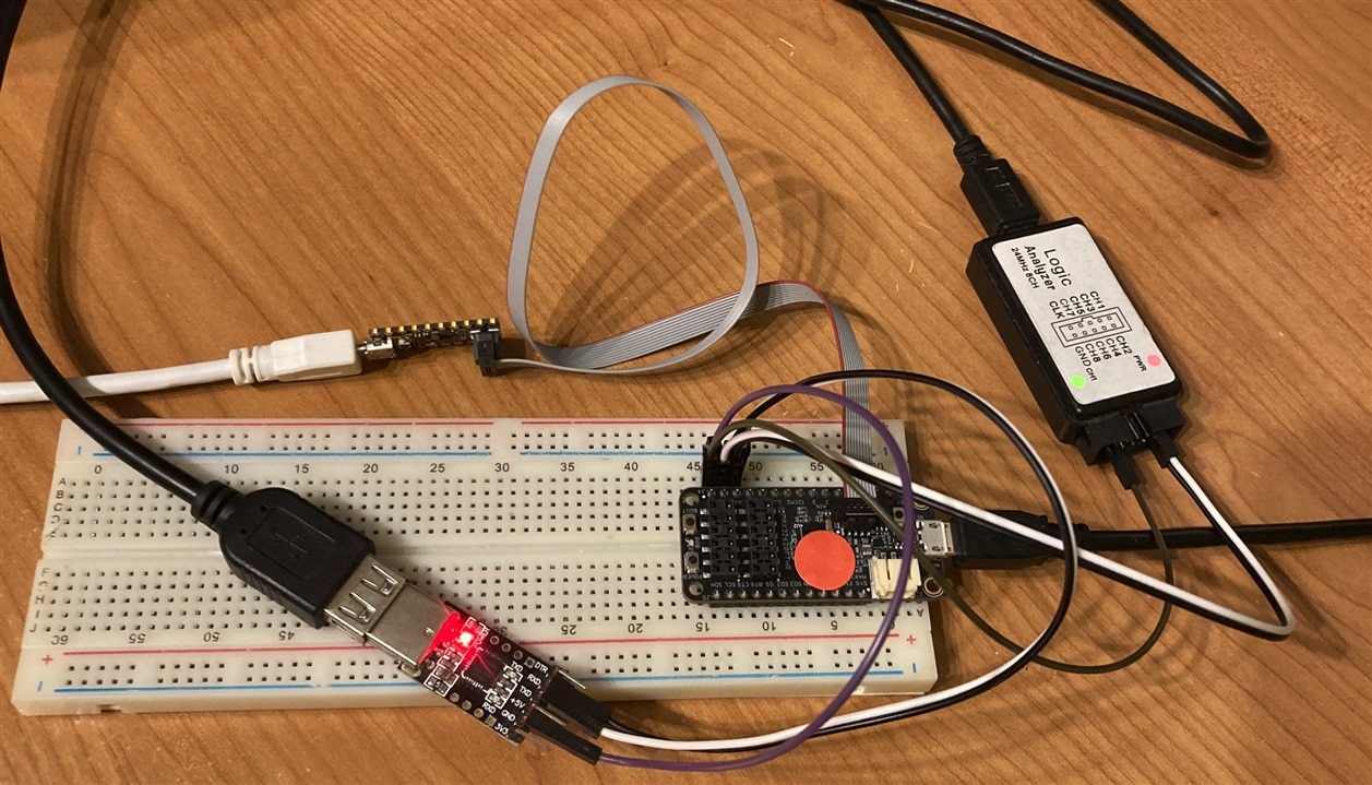
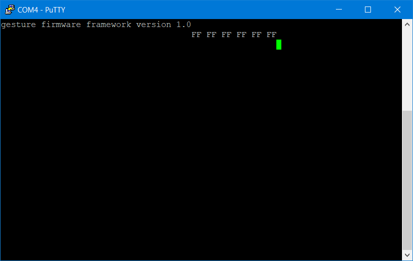
The MAX25405EVKIT comes with a MAX32620FTHR board which is preprogrammed with custom binary file for the gesture recognition. The application note at Maxim Gesture Sensor EVKit Serial API (maximintegrated.com)

mentions "The serial interface can be implemented over the Universal Serial Bus (USB) virtual serial port or over a Universal Asynchronous Receiver-Transmitter (UART). The EV kit is shipped configured to use the USB serial port to work with the EV kit PC Graphical user Interface (GUI). If a UART serial interface is desired, custom firmware in binary format is available."

Upon researching more, I found the firmware_framework code that contains the code for gesture recognition compiled using mbed compiler.

The readme file says that a file called interface.h and interface.c define the communication protocol. When I open the interface.c file, I can see a comment in the code that says Option to implement serial API over UART instead of USB but there is only a MACRO set as #define macro_name 0 

I tried to change the 0 to 1 and compile the code, however, it does not compile successfully. The USBDevice library shows some error while compiling. 

Did anyone try to change the serial API over UART instead of USB? Was it successful?  

EDIT: I have successfully compiled the code for UART. However, I'll do some experiments and write introductory blogs before I re-program the MAX32620FTHR board with my firmware. 

  • Sign in to reply
  • Cancel

Top Replies

  • misaz
    misaz over 2 years ago in reply to misaz +4
    Today I found root cause of the issue. Issue is caused by invalid assembly code generated by modern ARM compiler. With older GCC compiler it works because it handle undefined behaviour used in code differently…
  • misaz
    misaz over 2 years ago +3
    I am curious how did you successfully compiled non-changed code? I started working with latest mbed-os but I was unable to compile it (missing toolchain) no matter of USE_UART_INTERFACE setting. Later…
  • BigG
    BigG over 2 years ago in reply to rsjawale24 +3
    I've create a very basic stripped down library based on the firmware framework using the latest MbedOS 6.16. github.com/.../Max25x05_MbedOS6 All it is doing is getting the raw pixel data. It is doing…
Parents
  • misaz
    misaz over 2 years ago

    Hi, today I tried flash the firmware to the device and my physical UART interface work when compiled with MBED OS checked to revision 0fdfcf7350896a9c0b57c4a18237677abfe25f1a and USE_UART_INTERFACE set to 1. AT least it respond to ver command. As of now I did not tried advanced commands yet. UART is on pins P3.0 and P3.1 exactly as you have connected. For sure I am attaching my build of firmware: https://misaz.cz/Public/files/max25405fw_real_uart.bin

    But, I had issues with flashing firmware to the device using bootloader. In my case after draging new firmware and waiting bootloader rebooted but FAIL.TXT file occured with description that flashing failed with error "The transfer timed out". I tired copy file from WIndows machine and also from Linux (Raspberry Pi) but in both case I received this error. Are you sure that you flashed firmware successfuly? After flashing firmware and reseting FTHR board "Maxim Serial Port" should dsiappear from Windows Device Manager. If you see Maxim Serial Port after "flashing", than your flashing procedure were unsuccessfull and your MCU still runs old (stock) firmware.

    Because I was unsuccessfull with bootloader then I used alternative way - JTAG probe. I flashed firmware to the MAX32620 MCU using PICO adapter and openocd with following command:

    "C:\Maxim\Toolchain\bin\openocd.exe" -s C:\Maxim\Toolchain\share\openocd\scripts -f interface/cmsis-dap.cfg -f target/max32620.cfg -c "init" -c "halt" -c "program D:/path/to/max25405fw_real_uart.bin verify"

    But this approach of course requires JTAG probe.

    For sure I am posting photo of my setup. I use FTHR board on breadboard. Here I connected CP2102 USB-to-UART converter connected to pins P3.1 and P3.0 of FTHR board and I also used logic analyzer to check UART signals. Last board is MAX32625PICO board which I used with debugging:

    image

    Then I was able to connect to open CP2102 COM port in Putty and execute some commands. Note that firmware has no echo feature, so typed commands are not visible and I had to enter Ctrl + J to send \n (by default putty sends \r on enter). But after sending commands I successfully received replies from firmware:

    ver
    reg read 0 6

    image

    • Cancel
    • Vote Up +1 Vote Down
    • Sign in to reply
    • Cancel
  • rsjawale24
    rsjawale24 over 2 years ago in reply to misaz

    Thanks! This actually helped. After flashing the firmware, I was not waiting long enough, I was thinking the firmware file is very small and as soon as I copy paste I was manually resetting the controller. However today after copying the binary, I waited for the MCU to reset and I got the fail file. Timeout error.

    I do not have PICO board for debugging nor do I have JTAG probe. I have a STM32 Nucleo board with STlink pcb. It has JTAG interface. I'm not sure if I can use that one.

    Otherwise I'll just purchase a new JTAG probe.

    EDIT: Can I use the MAX32625PICO board for programming the MAX32620FTHR board? Or I have to buy JTAG probe separately?

    • Cancel
    • Vote Up 0 Vote Down
    • Sign in to reply
    • Cancel
Reply
  • rsjawale24
    rsjawale24 over 2 years ago in reply to misaz

    Thanks! This actually helped. After flashing the firmware, I was not waiting long enough, I was thinking the firmware file is very small and as soon as I copy paste I was manually resetting the controller. However today after copying the binary, I waited for the MCU to reset and I got the fail file. Timeout error.

    I do not have PICO board for debugging nor do I have JTAG probe. I have a STM32 Nucleo board with STlink pcb. It has JTAG interface. I'm not sure if I can use that one.

    Otherwise I'll just purchase a new JTAG probe.

    EDIT: Can I use the MAX32625PICO board for programming the MAX32620FTHR board? Or I have to buy JTAG probe separately?

    • Cancel
    • Vote Up 0 Vote Down
    • Sign in to reply
    • Cancel
Children
  • BigG
    BigG over 2 years ago in reply to rsjawale24

    Mbed uses Arm Mbed DAPLink. To check if there is suitable firmware use https://daplink.io/

    Another consideration, if you had the Arduino bootloader installed (i.e. if you plug in the USB cable into the board and the computer and a folder pops up on your computer screen then you have a bootloader installed), is to make allowances for the bootloader inside Mbed Studio. This is a setting applied during compile so that it does not try and override the bootloader memory. It will usually fail because of this.

    On a Linux computer you can see the bootloader used at: .arduino15/packages/Maxim/tools/daplink/1.0.2/bootloader

    You can see that a "mount point" is used in the Arduino platform.txt file for the MAX32620FTHR board: tools.daplink.upload.mountPoint=BOOTLOADER

    When you use the Native USB Port option in Arduino to flash firmware onto the MAX32620FTHR it uses compiler options in the boards.txt file.

    max32620_fthr_bl.build.extra_flags=-mthumb -D__SYSTEM_HFX=96000000 -DTARGET=MAX32620 -DTARGET_REV=0x4332 -DUSBCON -DMAX32620 -DMAX32620FTHR_BOOTLOADER -DARDUINO_MAXIM

    Then you have to hunt for it, as it's buried... is the linker script file (max32620_bl.ld). Here it gives us what we want to know:

    MEMORY {
        FLASH (rx) : ORIGIN = 0x00010000, LENGTH = 2M - 64K /* start from 0x0, allowing bootloader */
        SRAM (rwx) : ORIGIN = 0x20000000, LENGTH = 256K     /* full-size SRAM, 256K */
    }

    Then in Mbed you'll need to adjust the targets.json file or make a mod in mbed_app.json to show a change in the ROM start position as well as size.

    "mbed_rom_start": "0x00000000"
    "mbed_rom_size": "0x00200000",
    • Cancel
    • Vote Up 0 Vote Down
    • Sign in to reply
    • Cancel
  • rsjawale24
    rsjawale24 over 2 years ago in reply to BigG

    Hi thanks for the detailed explanation, but I have not flashed arduino bootloader in the MAX32620. It is the original bootloader from Maxim only. 

    • Cancel
    • Vote Up 0 Vote Down
    • Sign in to reply
    • Cancel
  • BigG
    BigG over 2 years ago in reply to rsjawale24

    yes, it is more likely than not one and the same, as it originates from Maxim.

    • Cancel
    • Vote Up 0 Vote Down
    • Sign in to reply
    • Cancel
  • BigG
    BigG over 2 years ago in reply to rsjawale24

    I just burned the bootloader onto the board using the Arduino IDE. I get two folders. One is DAPLink and the other is Bootloader... you would also get the Bootloader folder by holding down the boot button when powering the board.

    Do you have the same?

    I just tested by using the following mbed_app.json file and it works - I could drag and drop the compiled bin file and it did not time out:

    {
    "target_overrides": {
    "*": {
    "platform.stdio-baud-rate": 115200,
    "platform.stdio-buffered-serial": 1,
    "target.printf_lib": "std",
    "target.mbed_rom_start": "0x00010000",
    "target.mbed_rom_size": "0x001F0000"
    }
    }
    }
    • Cancel
    • Vote Up 0 Vote Down
    • Sign in to reply
    • Cancel
  • rsjawale24
    rsjawale24 over 2 years ago in reply to BigG

    I get the bootloader drive when I hold the boot button while powering it up. But when I drag and drop a binary file into the bootloader file, it says timeout error

    • Cancel
    • Vote Up 0 Vote Down
    • Sign in to reply
    • Cancel
  • rsjawale24
    rsjawale24 over 2 years ago in reply to BigG

    image

    This is my details text file inside the bootloader drive

    image

    • Cancel
    • Vote Up 0 Vote Down
    • Sign in to reply
    • Cancel
  • BigG
    BigG over 2 years ago in reply to rsjawale24

    It's pretty much the same... key is bootloader version

    # DAPLink Firmware - see https://mbed.com/daplink
    Unique ID: 000000009ecfc04000000000000000000000000097969904
    HIC ID: 97969904
    Auto Reset: 0
    Automation allowed: 1
    Daplink Mode: Bootloader
    Bootloader Version: 0242
    Git SHA: 33e3ba1b4a53f190d35bd40421a6c67f9c1842a2
    Local Mods: 1
    USB Interfaces: MSD
    Interface CRC: 0xbb0e972e

    • Cancel
    • Vote Up 0 Vote Down
    • Sign in to reply
    • Cancel
  • misaz
    misaz over 2 years ago in reply to rsjawale24

    Hi. After yet another experiments and some hints from BigG I successfully found the cause of the issue.

    It looks that DAPLINK checks for binary data and most probably checks some data in binary (I gues it checks for vector table). The reason is that by default our firmware is compiled with addresses starting at zero which are used for DAPLINK firmware. You need to recompile with address skipping bootloader. Change contents of mbed_app.json file to following:

    {
    	"target_overrides": {
    		"*": {
    			"target.mbed_rom_start": "0x00010000",
    			"target.mbed_rom_size": "0x001F0000"
    		}
    	},
        "config": {
            "main-stack-size": {
                "value": 65536
            }
        }
    }

    Then open mbed-os/targets/TARGET_Maxim/TARGET_MAX32620C/device/TOOLCHAIN_GCC_ARM/max32620.ld file and update line #36 containing FLASH memory definition to following:

    FLASH (rx) : ORIGIN = 0x00010000, LENGTH = 2031616

    This change linker script for TARGET_MAX32620C (note the C at the end). I am not sure why my MBED environment selected target ending with C but I recommend change this line in both TARGET directories.

    After that you get firmware which you will be able to flash to the device.

    • Cancel
    • Vote Up +2 Vote Down
    • Sign in to reply
    • Cancel
  • rsjawale24
    rsjawale24 over 2 years ago in reply to misaz

    Thanks. I will try it. I'm using the online mbed compiler so will have to look for those files in mbed-os. Thank you BigG and misaz

    for helping me

    • Cancel
    • Vote Up 0 Vote Down
    • Sign in to reply
    • Cancel
  • rsjawale24
    rsjawale24 over 2 years ago in reply to rsjawale24

    it seems that this feature is not supported in online compiler. Will have to try in CLI on windows

    • Cancel
    • Vote Up 0 Vote Down
    • Sign in to reply
    • Cancel
element14 Community

element14 is the first online community specifically for engineers. Connect with your peers and get expert answers to your questions.

  • Members
  • Learn
  • Technologies
  • Challenges & Projects
  • Products
  • Store
  • About Us
  • Feedback & Support
  • FAQs
  • Terms of Use
  • Privacy Policy
  • Legal and Copyright Notices
  • Sitemap
  • Cookies

An Avnet Company © 2025 Premier Farnell Limited. All Rights Reserved.

Premier Farnell Ltd, registered in England and Wales (no 00876412), registered office: Farnell House, Forge Lane, Leeds LS12 2NE.

ICP 备案号 10220084.

Follow element14

  • X
  • Facebook
  • linkedin
  • YouTube