Thanks to rscasny, kmikemoo and members who helped with the software licensing issue. I got the license without any problems to test the HMIST6200 in a virtual environment first.
The EcoStruxure Operator Terminal Expert allows the design of user interfaces for the interaction between the operator and the controlled machine. The ST6200 has two network interfaces: the Ethernet and the Serial Line both using the ModBus protocol. Since I was using the Harmony Hub on the Serial Line I decided to use the Ethernet interface to connect the HMI. By the way, this post shows how it works with the simulation in the Operator Terminal software.
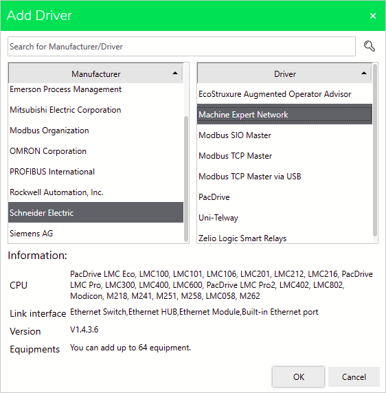
Fisrt, it is required the configuration of the interface with the HMI. There is an important number of Manufaturers to connect the interface. This time, the Machine Expert Network from Schneider Electric must be selected to operate the PLC from the HMI.
| {gallery}Driver Configuration |
|---|
|
IMAGE TITLE: Adding Schneider Electric Driver |
|
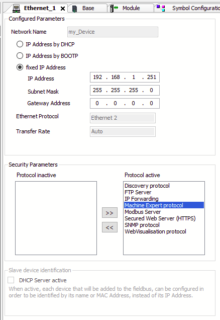
IMAGE TITLE: Machine Expert Protocol added to active protocols |
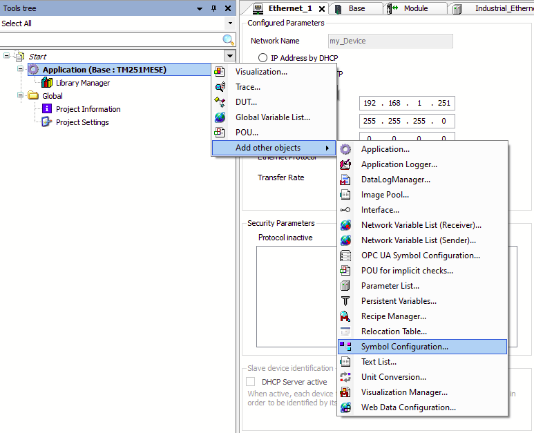
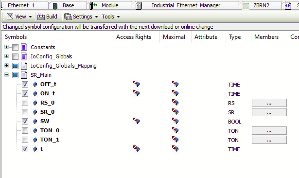
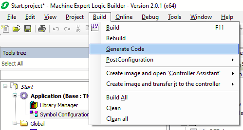
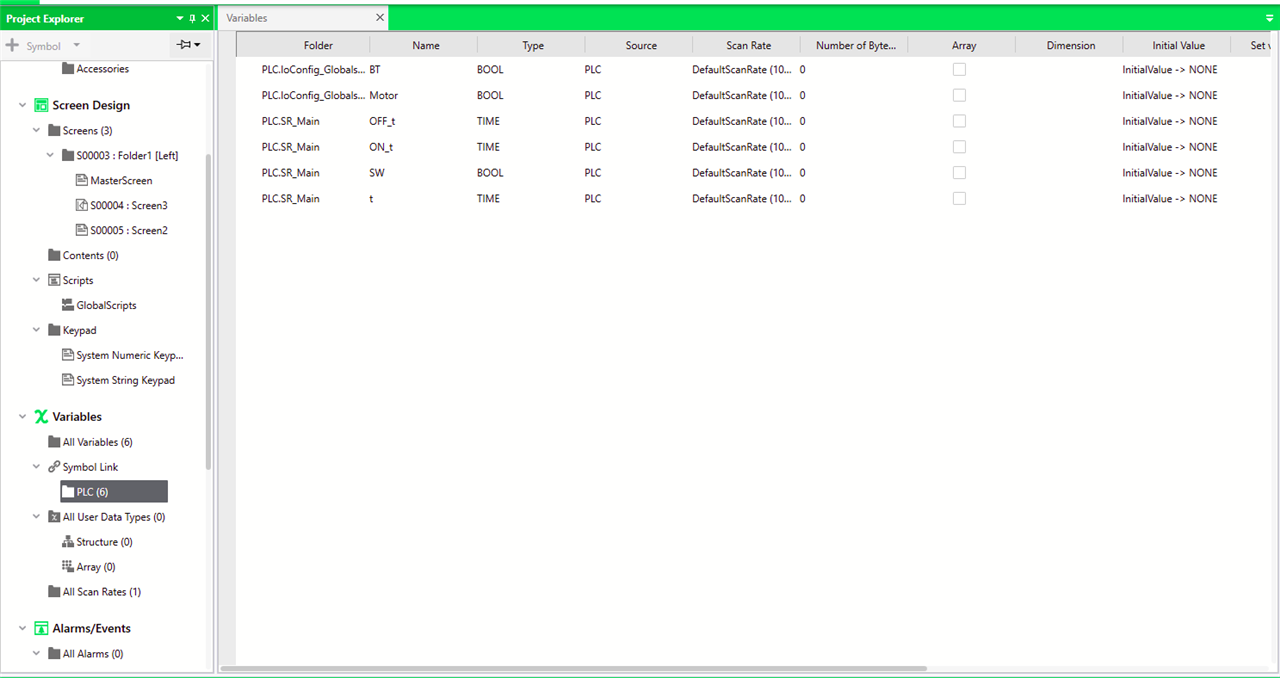
It is observable that the M251 is available in this driver. NOTE: The interface has changed its name from SoMachine Network. In the other hand, the Machine Expert protocol must be added to the selected Ethernet interface for data sharing, Otherwise, the HMI will not be able to control the variables in the PLC. The variables should be shared with the HMI by the addition of a Symbol Configuration component in the Machine Expert software. To do this, in the Tool Three you must add this component. After that, you are able to see those variables involved in the project; checking a variable will share that information with external components like the Operator Terminal. Finally, in the Variables section of the Operator Terminal Software, click on Symbolic Link to add the .xml file generated in order to create the link to the variables in the PLC. You must be able to see the result like the following,
| {gallery}Symbol Configuration |
|---|
|
IMAGE TITLE: Adding a Symbol configuration |
|
IMAGE TITLE: Selecting variables to share an access rights (R/W) |
|
IMAGE TITLE: Option to generate base files for the interface |
|
IMAGE TITLE: Symbolic Link of the variables |
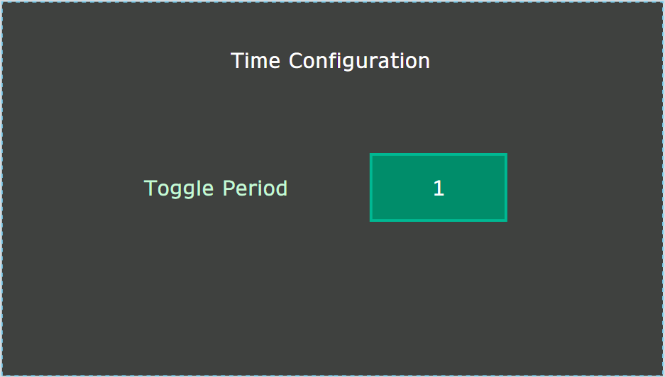
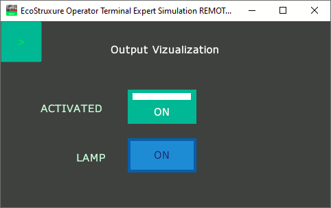
In the Screen Design section, I created a Left type folder in order to navigate by a side menu. I added two screens, one for the activating and monitoring of I/O variables and the other for the oscillation time variator.
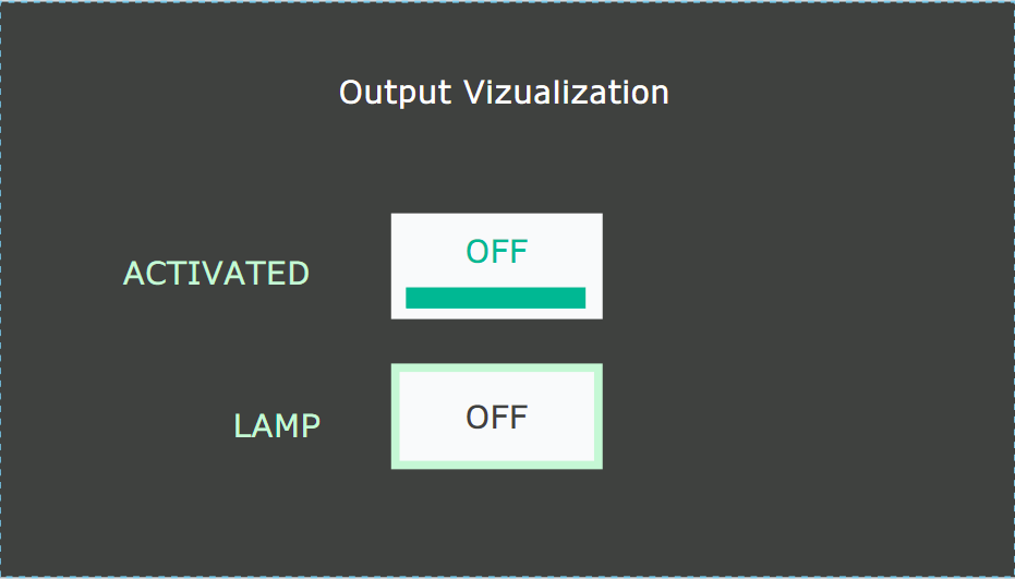
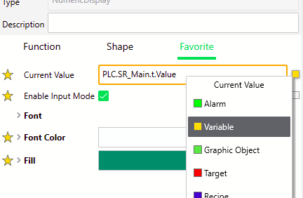
To link a component to a variable, you just need to add the link to the Current Value property of the corresponding element. You have to be careful because there are two possible ways to do this, one for manually setting value and a second, with the small square on the right, to link the variable.
To simulate the interface without operating the PLC you have the Device Simulate option; this option is used when you want to validate the user experience of the interface. If the full interaction and data management is required, you must use the Simulation option. These options are active in the play button in the top ribbon. for the Simulation and download to device options you must have a license.
The first time I tested the HMI, I had a connection failure. You can verify this problem if the interface shows a RED EDGE on the elements that interact with the PLC.
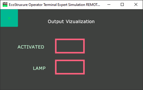
There are two reasons for this issue, the PLC is not available in the network configuration or the Encrypted Communication is enabled in the Equipment security. To solve the second scenario, you must navigate in the System Architecture > Driver > Added driver to the project and click on the corresponding interface. On Basic properties you can see the commented option checked, just uncheck it and test again.
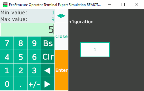
Fortunately, its use is very simple and you can program with minimal effort to maximize the utility of your interface. An example is the timming configuration of the system, with a touch gesture in the linked object you are able to configure the time easily.
