Introduction
In this post I'll be testing the Molex's Industrial SPE connector and cable assembly lineup, specifically the 220957 Series, rated IP67; especially for the industrial environments.
These are the specific part's I've used in my setup:

Wiring up the Molex's SPE PCB Jack
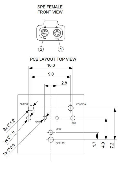
Mounting the PCB jack requires a specialized footprint and it's hard to mount on to the generic perfboard.
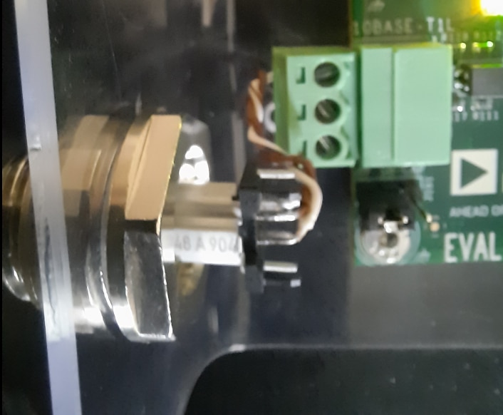
I began by connecting the wires, ( shorter ones, which are salvaged from a Cat6 cable) to the Molex's SPE PCB jack. I'm not entirely sure if this is the right way to connect wires to this vertical jack . One thing that stood out during soldering was how well the jack's plastic housing held up; despite direct heat from the soldering iron, there was no melting or deformation of the plastic support of the SPE jack.
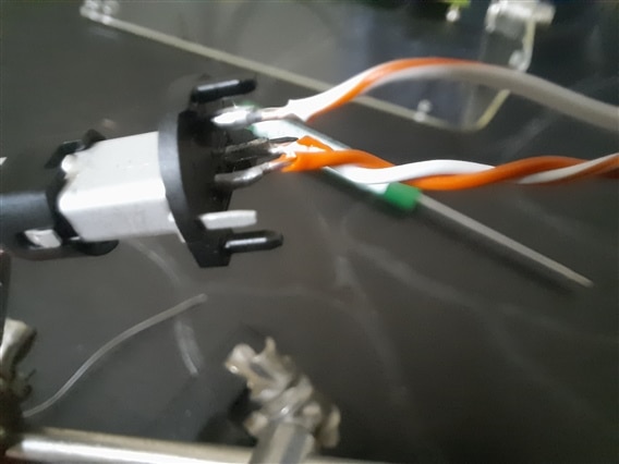
I initially included the shielding wire attached to the connector, but after testing both configurations, the difference in performance was negligible. This was probably due to the minimal EMI noise in my testing environment and the cable length is only 1 meter, which is short when compared to the 10BASE T1L standard's maximum reach of 1 kilometer.
Molex's PCB jack spec's are interesting, supporting higher data rates but the ADIN1100 and ADIN1110 are only 10BASE-T1L compliant and the max data rate of the link is limited to 10Mbits / sec.
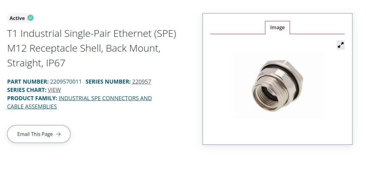
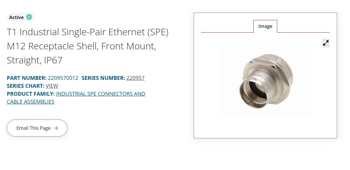
Attaching the Molex M12 Receptacle Shell Mount
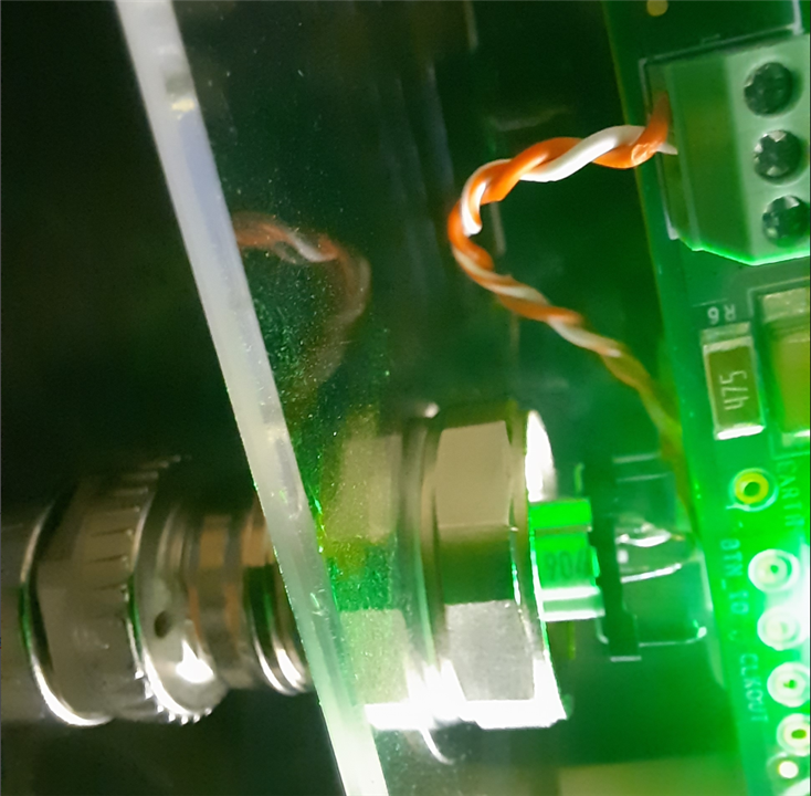
So for my actual installation, I ended up mounting the shell mounts onto transparent acrylic sheets as they are provide a better view of everything inside the assembly and also part of the reason being I couldn't find proper enclosures big enough and with the proper IP rating.
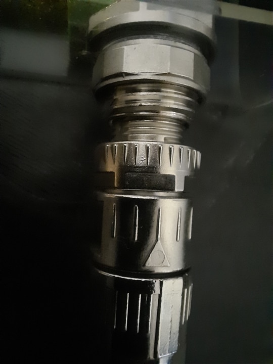
Now in terms of sealing and protection, the rubber washers protect against dust and moisture coming in from the outside.
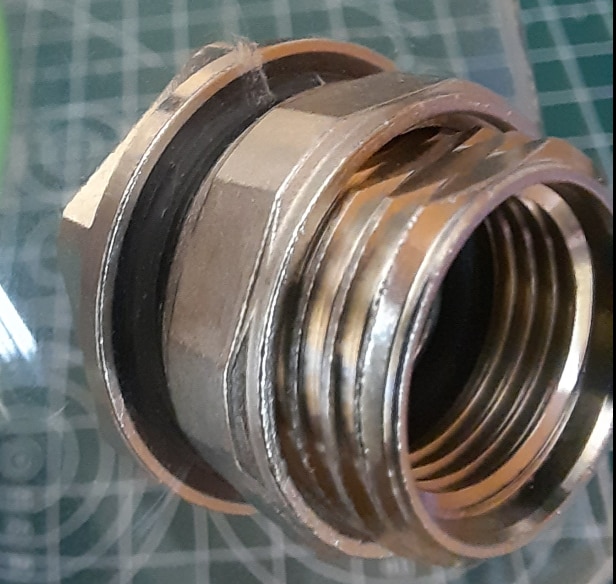
The inner washer makes sure that the M12 cable assembly is cinching up tight and stays that way despite the vibrations.And just as JWx mentioned in his forum post, it provides IP67 rating only in mated condition along with the Molex's Plug Cable.
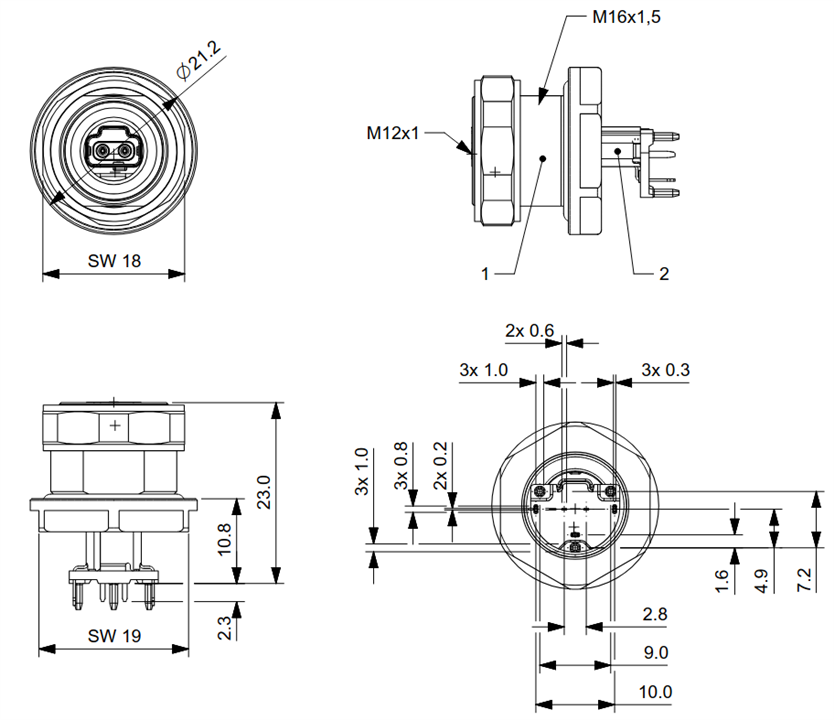
Here's the Front Mount dimensions and how the PCB mount fits into it.
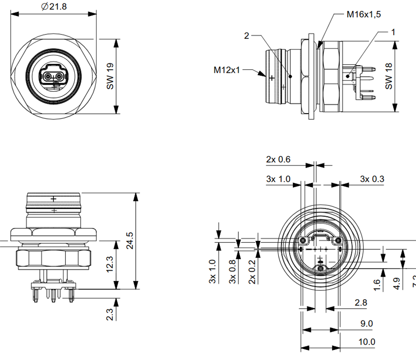
Here's the Back Mount dimensions and how the PCB mount fits into it.
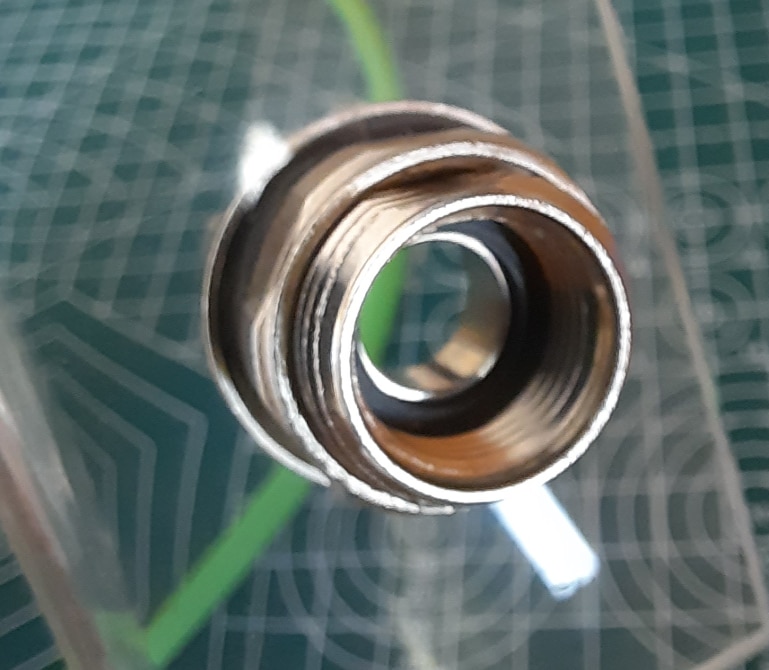
Here's some close up shots of the SPE mounts in my setup, the first one is the back mount
and the second one's the front mount attachment.
The back mount cannot be adjusted easily (i.e removed or tightened) without opening the enclosure, a more secure option when used on the outdoor units.These SPE mounts are made from brass (handles mechanical stress well and doesn't corrode easily on its own) and plated with Nickel (extremely resistant to oxidation, moisture, and the kind of atmospheric corrosion in outdoor environments).
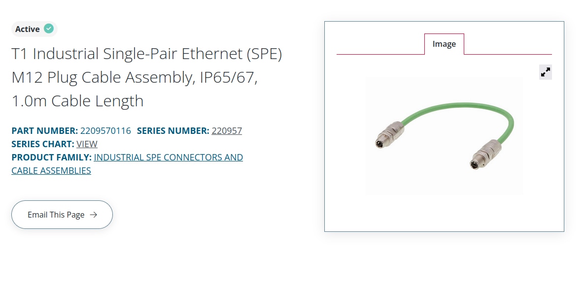
Connecting using the Molex's T1 SPE Plug Cable Assembly
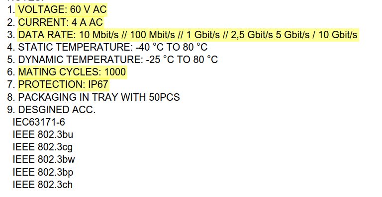
I gotta admit that this is my favorite cable in the kit, there's many reasons apart from it's design. First, just like all the Molex parts provided in the kit, this cable also handles up to 60V AC and 4 amps, which is quite impressive for the SPE's PoDL applications. Second, it has wide operating temperature range enough to use it in freezing winters or hot summers without cracking or degrading. The connector is also rated for 1000 mating cycles which is plenty for a semi permanent industrial installation.
The top part i.e the M12 screw attachment (labelled as 2 in the drawing) is the only part that rotates to screw into the front/back mount
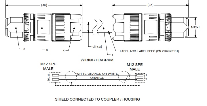
There's also an arrow provided on it to properly orient the connector during the connection of SPE cable and the mount.
The cable itself is PUR(Polyurethane), jacketed in green, which is the standard color coding for SPE industrial cables, making identification easy in a busy panel or installation.
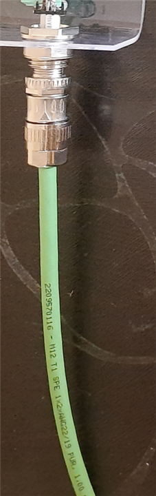
The M12 nut, hex nut and body shell are all brass with nickel plating, which protects against rust and corrosion in outdoor and humid conditions.
Another interesting detail worth noting is that the copper contacts inside the cable assembly are gold plated which is a meaningful design choice since it'll have better corrosion resistance over time, and more reliable signal integrity compared to standard tin plated contacts.
ADIN1100 and ADIN1110 with Molex Connectors and Cables
I've followed connecting the EVAL-ADIN1110EBZ and EVAL-ADIN1100EBZ as per the instructions provided in the user guide,
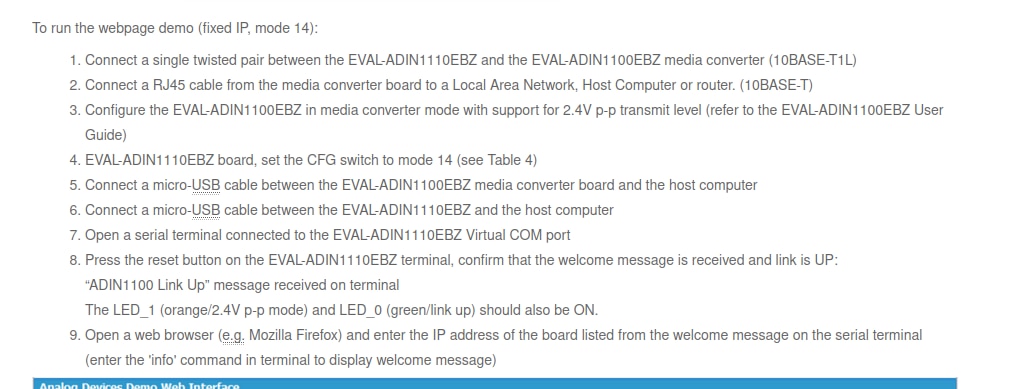
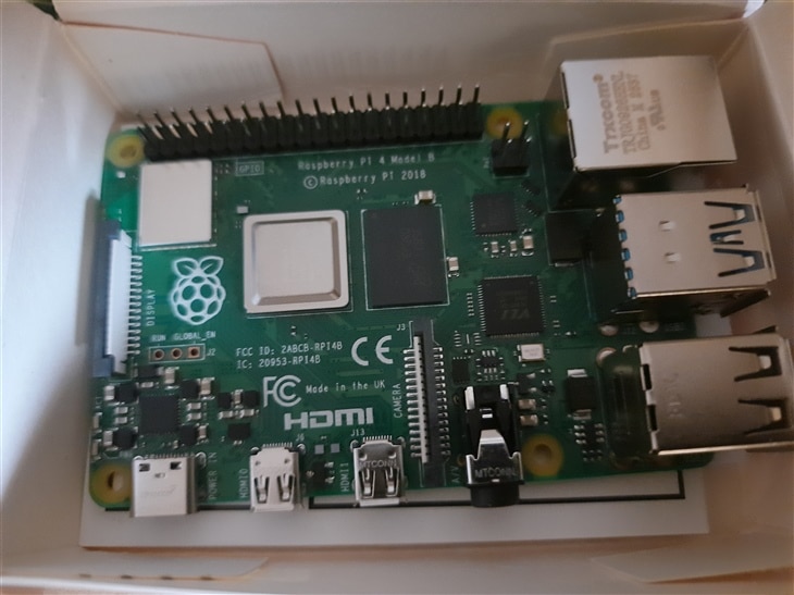
and the host computer I used in my setup is RPI4-MODBP-4GB.
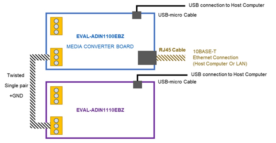
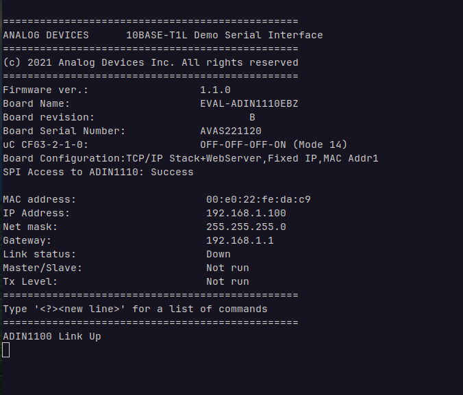
Then I connected the EVAL-ADIN1100EBZ to the RPI4-MODBP-4GB and observed the stats from the webpage hosted on the EVAL-ADIN1100EBZ. The IP address of the webpage is provided through the serial connection.
MSE stands for Mean Square Error and this is the link quality indicator, measured in decibels and the more negative the number the better.The link strength in my setup was consistent at -37.2 dB which seems pretty much stable.

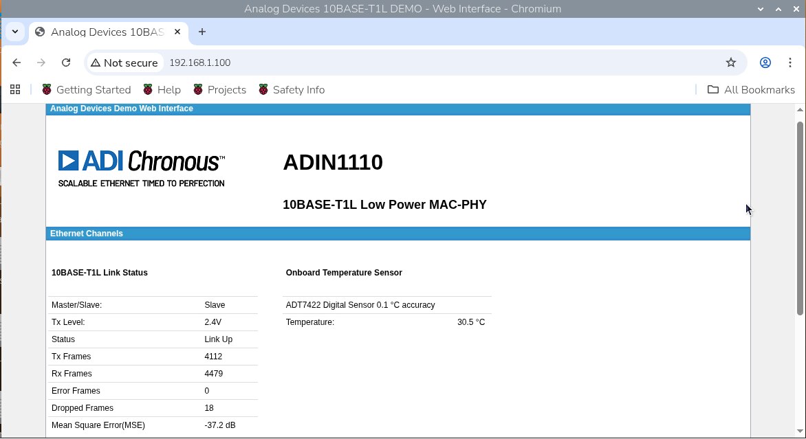

I still have to investigate the reasons for the dropped frames, I did change the wires but still there's some dropped frames; probably it's related to processing not the connectors and wires.
ADIN1100 and CN0575 with Molex Cables and Connectors
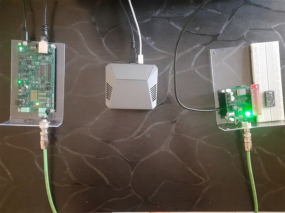
I connected the EVAL-ADIN1100EBZ and EVAL-CN0575-RPIZ using the Molex's T1 SPE cables and assemblies as shown below
I've connected the RPI4-MODBP-4GB to the serial port of the EVAL-ADIN1100EBZ and ran some inbuilt tests (which are provided in the default firmware) to check the link quality.

The link strength (MSE) was consistent at -37.2 dB.

Here's the log with the frame generator mode of EVAL-ADIN1100EBZ's and the link quality was consistent at the similar level, the Rx indicates the count of frames received by the PHY and Err is the number of frames with errors, which is zero so there's nothing wrong with the cable, connectors or termination.

The local ping results were also pretty consistent with zero losses.

Arrival of Pi 4
Also got my other RPI4-MODBP-4GB yesterday. Thanks E14Alice and JoRatcliffe for prompt shipment, despite the memory-driven price variations.