


Introduction
This part is about upgrading the current AGM battery bank and 4x parallel BQ25798 charger setup, to something more robust and powerful.
As discussed in the previous post, there are two main issues with the lead acid setup:
- The overall battery capacity is too small
- The recharge time (which happens during driving, from the vehicle’s generator) is way too long, and cannot keep the batteries charged enough to run in a ‘self-sufficient’ manner.
The conclusion I arrived at is that a roughly 1kWh battery is needed with a 20A+ charger.
For more details about how I got these numbers, check the previous part, I don’t want to pad out this post with repeat content.
Battery Candidates
My first step was to figure out what sort of battery would be ideal. I had a few constraints:
- I did not want to use Li-ion or Li-Po batteries, as they have a tendency to go boom in very hot temperatures, or when stupidity is encountered. I do not trust myself. Not burning down my car would definitely be a useful feature.
- Lead-acid, even very fancy AGM batteries suffer from two main problems: weight, and depth-of-discharge. This essentially rules them out completely.
These constraints narrow options down to two possible chemistries, that I can obtain and work with. I’m certain there’s some exotic battery type that costs more than my car that would be a great fit, but for obvious reasons, it’s not viable.
Candidate 1: NiMH
The tried and tested approach. Hybrid cars have used these for over 2 decades now, for basically the same exact reasons as mine. They do have some depth-of-discharge issues, but less severe than AGM. The energy density is way higher too, so they are less heavy and smaller for the same capacity.
Obtaining large NiMH batteries turns out to be a challenge though, it’s a niche market.
Candidate 2: LiFePO4
Looking at the name, it might look like this is another lithium battery that likes to violently express its dislike when rude things happen to it, but it turns out, that’s not the case. LiFePO4 batteries do not light on fire, do not explode, etc, even when punctured. They do obviously release some nasty chemicals and make a mess, but they are significantly safer in this aspect than even NiMH.
They are similar to Li-ion or Li-po in most ways, except have slightly lower energy densities, and run at a lower voltage: the nominal value is 3.2V, instead of 3.7V.
The energy density is still significantly higher than NiMH though, and they handle deep cycling insanely well. Limiting discharge depth by 10-20% easily gets us to 10000+ cycles, which translates to over 100 years in my use case. The AGM batteries lasted 6 months.
There’s one minor issue. These batteries cannot be charged below 0C at all, but more like 5C if we want to be safe. That will be a massive problem in the winter, but let’s just sweep this issue under the rug for a moment.
The only concern at this point was price and availability. Thankfully, LiFePO4 batteries got extremely popular for off-grid solar systems, and they are readily available. The prices are very compelling too.
The New Battery
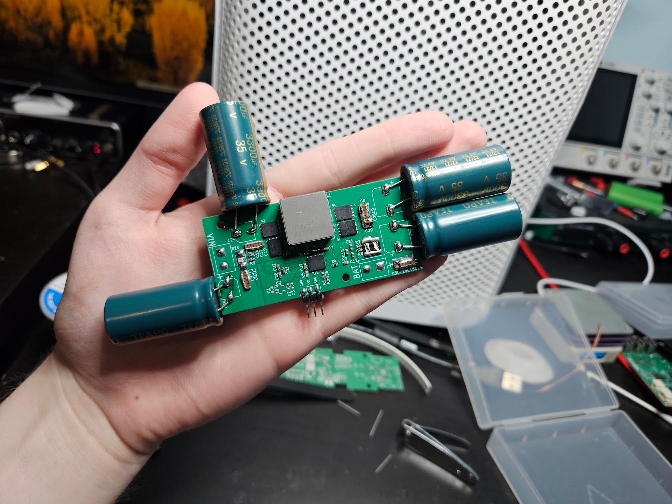
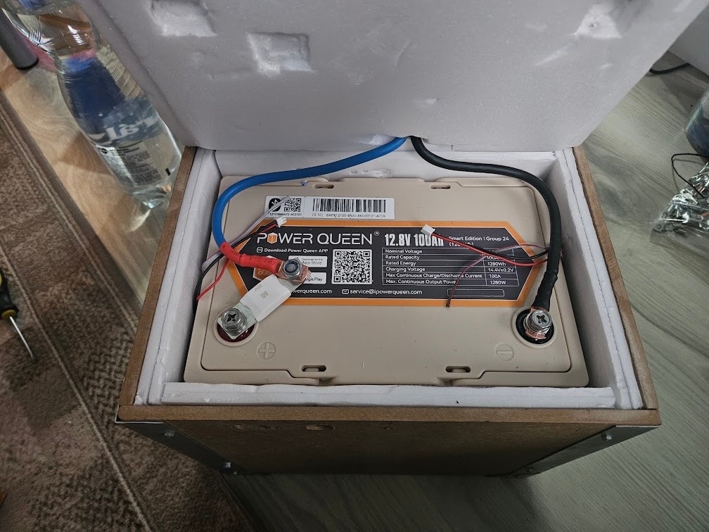
After some research, I ended up buying a 1.28kWh, 100Ah LiFePO4 battery. The price was good, the reviews looked fine, so it seemed like the perfect option.
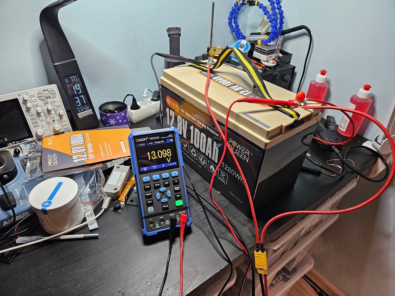
(yes, I really should’ve cleaned up a bit, but oh well)
Initially, everything seemed fine. Attached some loads, capacity was exactly as advertised.
However, a big problem surfaced: when charging, the BMS cut off at 13.7V, when the battery should be able to charge way higher. I did a few discharge cycles to see if things improved, but not really.
At this point, I decided to contact customer support, and get a replacement. Initially, they were relatively helpful, although they completely refused to cross ship a replacement for some reason, so I was stuck waiting weeks to get the new battery.
When the new one arrived, same issue. The BMS was cutting out way too early. I suspected that the issue was unbalanced cells internally, and one of them reaching a higher voltage than the others. Unfortunately, the battery is glued or ultrasonically welded in a way that it’s impossible to open up, and I wouldn’t want to lose my warranty on a dodgy battery anyways.
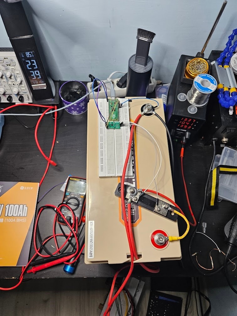
I reached out to customer support again, to explain what is happening. I even set up a system to log voltage and current to InfluxDB, and made a Grafana dashboard to have fancy plots of everything. After sending extremely detailed data to the manufacturer, they essentially told me that I have no idea what I’m doing and they don’t really want to deal with me anymore so just send the battery back, and they’ll refund me, no replacements, no upgrades, no nothing. So that’s 2 months wasted on unreliable batteries.
A massive disappointment honestly, according to everything I’ve read, these batteries should be quite good quality. I am 99% certain that the issue was unbalanced cells, which is a big fail on the part of the manufacturer. Getting two of these batteries in a row means that this is probably a widespread issue.
After some more research, I didn’t find any other good candidates for batteries, so I decided to buy another battery from this manufacturer, but this time, one with a “smart” BMS, that can connect to a mobile app. My hope was that I could sniff some useful data from Bluetooth, and possibly see cell voltage readings and BMS fault reasons.
The new battery had the same exact issue. The BMS cut off way too early. Looking into the “smart” BMS, I discovered that someone already reverse engineered the protocol, so I had no trouble writing some code to log the BMS data to InfluxDB. After looking at the numbers, my suspicions were confirmed. Cell 2 in my battery was resting at a significantly higher voltage than all the other cells.
The next 2 weeks were spent trying to get the cells balanced. I had relatively little success at this point, although a minor improvement did happen, and I was able to charge to 13.95V before the BMS intervening. The imbalance still persisted, but I just decided to not charge the battery to more than 13.9V to sidestep the problem somewhat. This would only result in a few percent of capacity loss, and maybe I could figure out a solution later.
The Cold Charging Problem
As mentioned earlier, LiFePO4 batteries cannot be charged in cold temperatures. Some more expensive battery models include a built-in heater, and in cold weather, the BMS disables charging, and uses the input energy to run the heaters instead.
This seems like a decent solution at first, but it’s another black box system. The BMS controls the heater somehow, with no explicit ability to turn it on, and the temperature sensor is almost certainly just glued to the outside of the cells. When the heater gets the outer shell of the batteries to a few degrees above freezing, I assume the BMS just enables charging immediately, and the battery gets damaged. The LiFePO4 cells are massive, and heating their outer shells to even 10+ degrees means nothing, if their centers are still below freezing. We will need some logic in our heater system to account for the heat having to reach the center of the cells, but we only have a temperature reading from the outer shell.
My solution was to add my own external heating. This is significantly worse in the sense that I am heating the outer plastic, which needs to heat the inside air, which needs to heat the cells, instead of just directly heating the cells. However, I get direct control over everything.
I got some heating films, big flexible sheets with glue on one side, and a long, snaking trace covering the surface, that acts as a heating element. I put two of these on the battery’s outer casing.
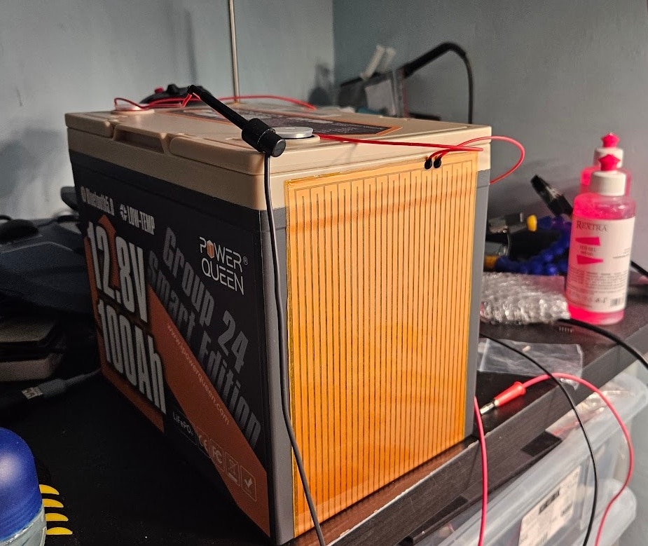
(one heating film is enough to cover one side completely, as visible in the picture, plus half of the bottom surface too)
I also added a bimetallic thermal fuse and a DS18B20 on both heating films, which I completely forgot to take a photo of, sorry.
The next step is insulation. Spending all that energy on heating the battery is useless, if the heat is not kept in.
A relative of mine made this lovely wooden box for me, that I padded out with multiple layers of XPS foam, typically used for insulating floors.

Added an XT60 and a GX12 connector temporarily, as this battery was essentially meant to be a drop-in replacement for the old AGM bank at this stage.
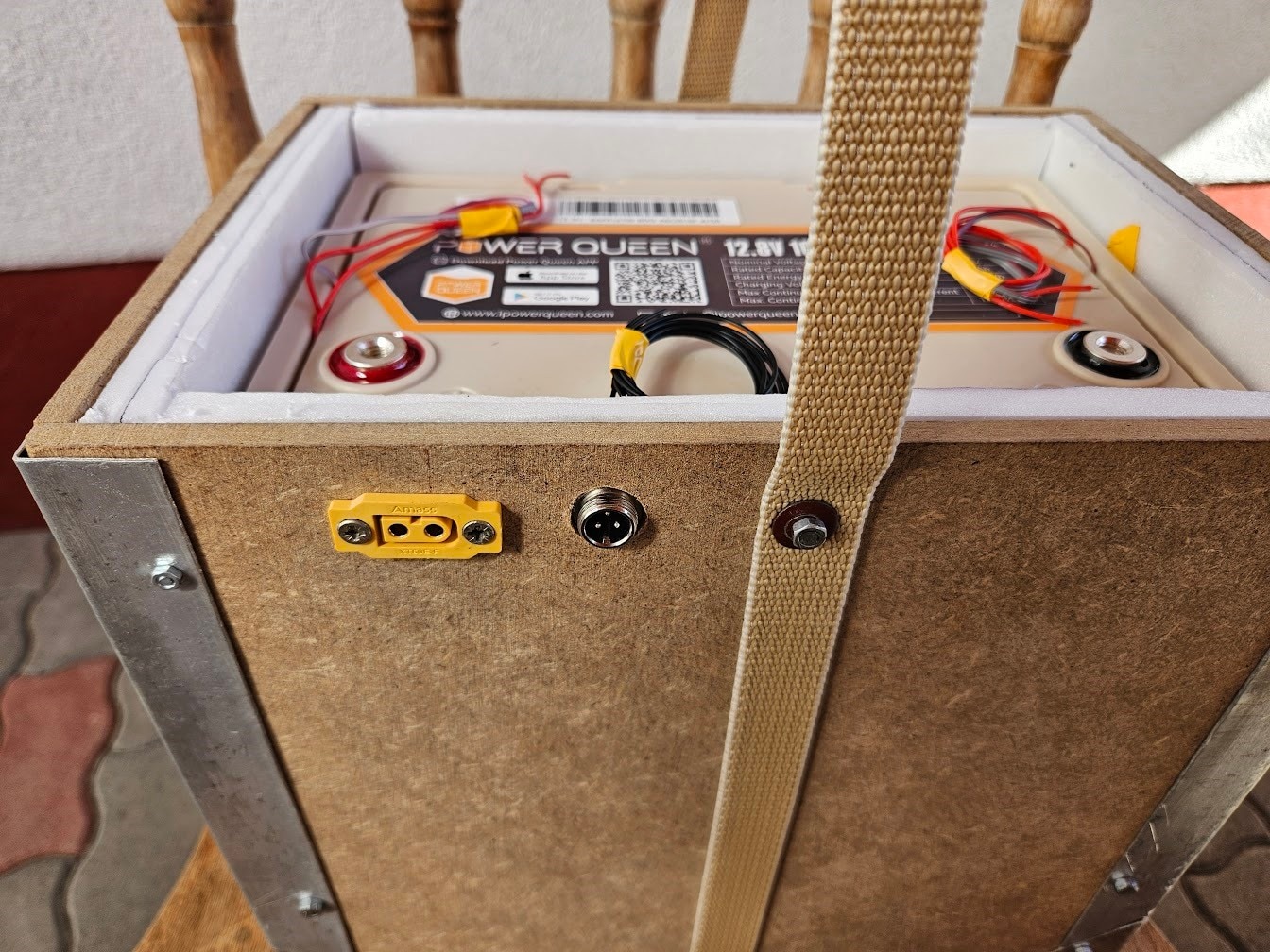
The heaters and temperature sensors were left unconnected for now, as it wasn’t yet cold outside, and hooking them up to the old system would’ve been a waste of time.
I hooked the new battery up for a short test period, and real-world battery life ended up being around 5 days. Perfect.
The Charger
The next issue to tackle is charging. As you might recall from earlier, four BQ25798 charger ICs were used, which means that a best-case maximum of 12A charging was possible. This is about half of what we need, and a terribly janky solution anyways.
I went searching for a sufficiently beefy charger IC, and I stumbled upon the BQ25756. This seemed like the perfect choice, it’s essentially the big brother of the BQ25798. It no longer integrates the FETs, but that’s fine. With a well-designed PCB and correctly chosen components, it should be capable of doing 20A.
Charger PCB v1
Emboldened by success with the very simple, integrated FET chargers from earlier, I thought this will be a cakewalk. In retrospect, I probably designed the worst PCB in the history of power electronics. I’ll do everyone a favor and not show it, let’s just forget it even existed.
The board barely ran, was unstable, had voltage spikes, OCP constantly triggered, etc.
Charger PCB v2
At this point, I probably had about 10% of the required knowledge to design such a charger. Obviously, I thought I knew everything at the time though. Same story as before really, just slightly less terrible.
This revision was significantly better, but still completely unsuitable for use. I followed the ‘add more caps’ methodology for solving stability issues, but with no success.
Charger PCB v3
After even more research and studying power electronics, I made a new revision of the board.
I did not actually get this made, for reasons that will become clear in a moment, but I believe this design should be okay-ish possibly (absolutely no reason to suspect that I might be overconfident here, this could never happen to me).
While designing this board and contemplating the meaning of life, and whether I’ll live long enough to produce enough revisions to end up with something that works, I went online to look for some power supplies for a different project. By complete accident, I stumbled upon something, that would make this project way simpler, and my wallet way lighter.
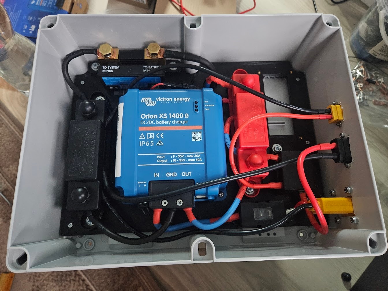
The Orion XS
The Victron Energy Orion XS is a DC/DC battery charger, that is EXACTLY what I need. If I could change something about it, I wouldn’t. It was made for the exact use case I need it for: charging a secondary battery in campers, from a car’s generator or main battery. It has a bunch of convenience features that will be extremely useful. But most importantly: it is a 50A, insanely efficient charger, that just works.
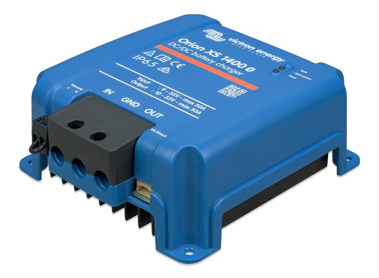
Power goes in, battery gets charged. Has Bluetooth and a fancy app, which is great for testing, but not that great for my project. However, there’s a “VE.Direct” port on there, which is electrically just UART, that lets me control it without Bluetooth. Absolute perfection.
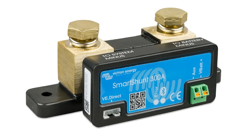
I also picked up their SmartShunt 300A, which is just a big shunt resistor with an MCU and some analog stuff on there. The price was right, and it gives me hassle free battery state-of-charge numbers, and also uses the VE.Direct port that I’ll be using for the charger itself.
While this setup was significantly more expensive than doing my own charger, it took somewhere between 10 to infinite times less effort to build, and it also has the advantage of actually working. All that’s left is to put everything together.
The Charger Assembly
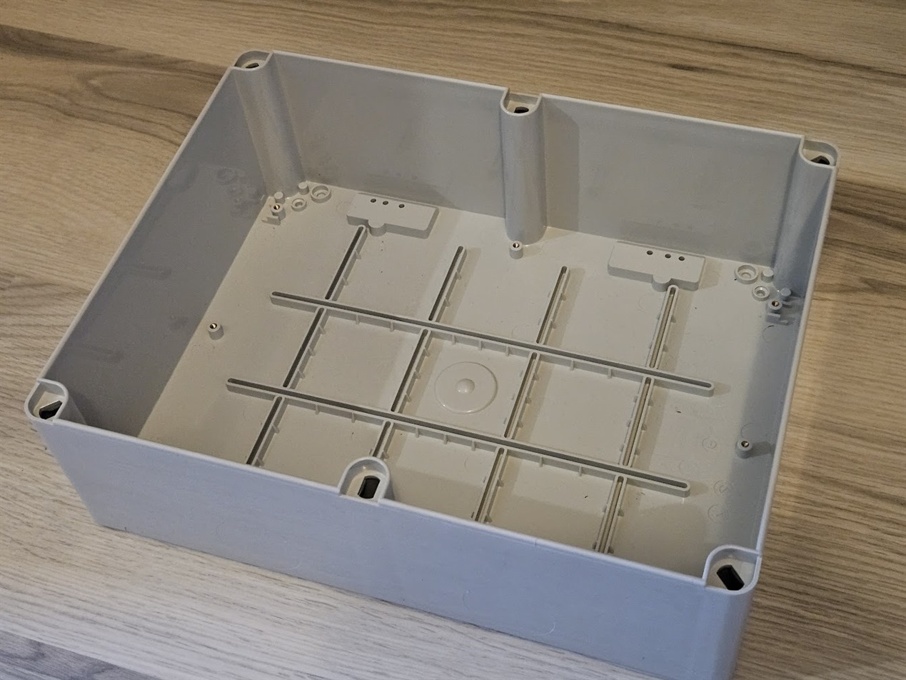
I got a big, waterproof(ish) box to put everything inside. It has almost the same width and height as the battery, so I can later mount it on top.
With a 50A charger, it made sense to wire everything for 50A. That brings some challenges though. 50A is no joke, especially in a car, where everything is constantly vibrating. That means it’s wire lug, bus bars, and big crimp tools time. And don’t forget fuses.
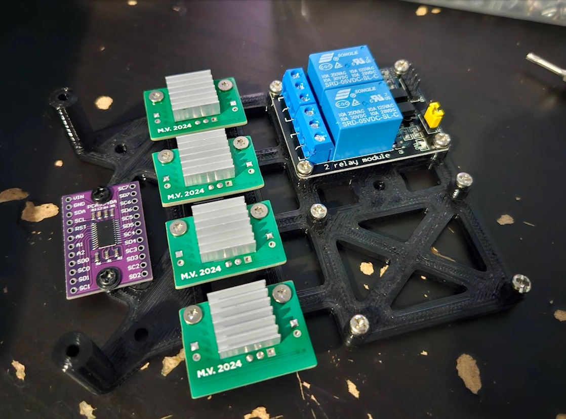
I couldn’t figure out any nice ways to mount everything inside, so I ended up designing and 3D printing a ‘baseplate’ that holds everything. This plate is then screwed into the big plastic box.
I put some brass threaded inserts into the box to help with mounting the baseplate, they are visible in the image above.
And here’s the baseplate with most of the components attached. There is no wiring yet, and the custom controller PCB is missing from the top right.
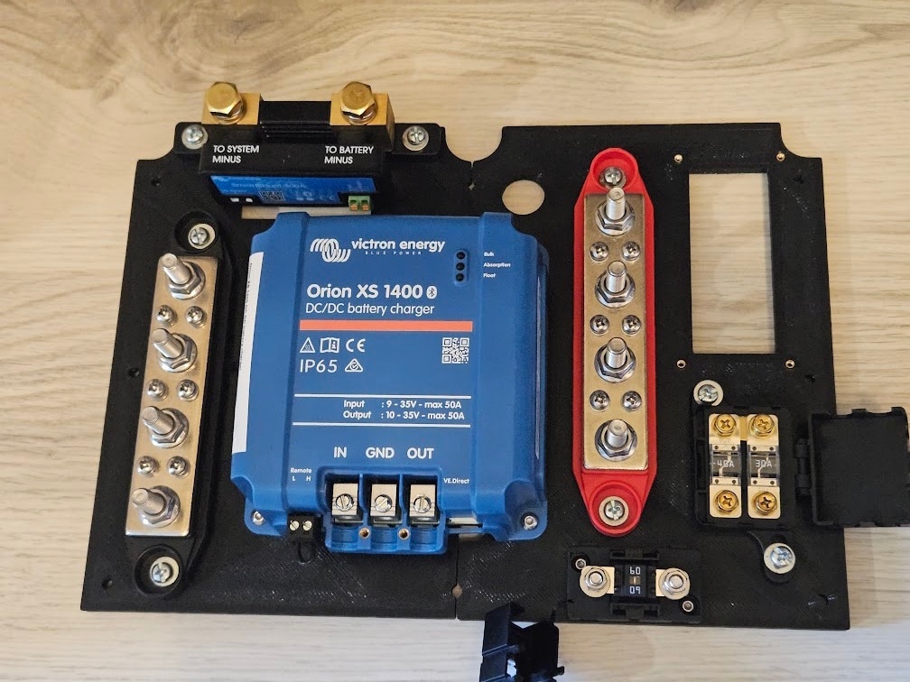
The 60A fuse in the bottom right is for the charger input, and the two smaller (40A and 30A) fuses are for the XT90 and XT60 outputs that will be on the box.
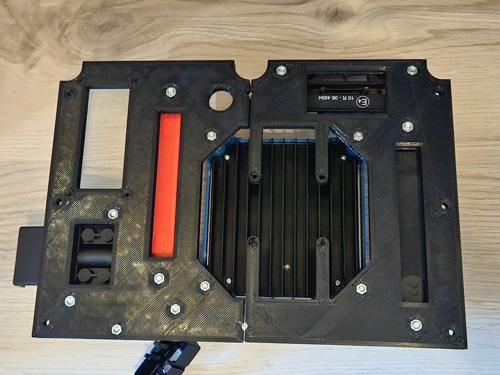
There’s a mounting pattern for a fan to add later, the charger will probably need some active cooling in the summer, but so far it has been running just fine with zero airflow. (The charger barely heats up, I measured ~98% efficiency, it’s very impressive)
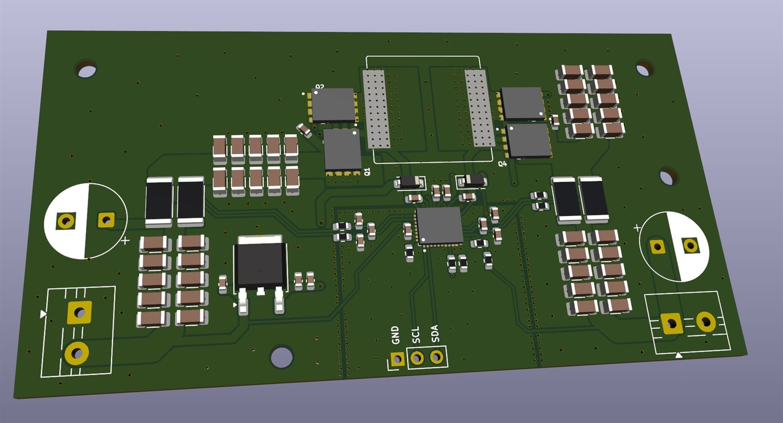
The controller board I designed hasn’t arrived yet, but here’s the 3D render of it:
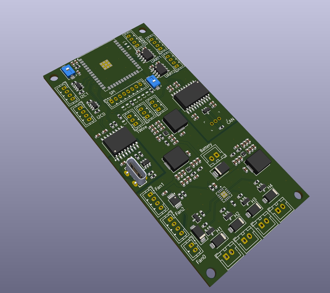
It contains an ESP32-S3 that runs all the logic, and also communicates with the LiFePO4 BMS over Bluetooth. There are two isolated UARTs to connect to the Victron VE.Direct ports (to avoid nasty ground loops, and also act as level shifters), an isolated USB port for programming and debugging, an isolated CAN bus port for future expansions, a bunch of fan headers, and heater power outputs.
This board will be hooked up to the ADIN1110 SPE transceiver and MAC, and the SPE link will connect the battery assembly to the SBC in the front.
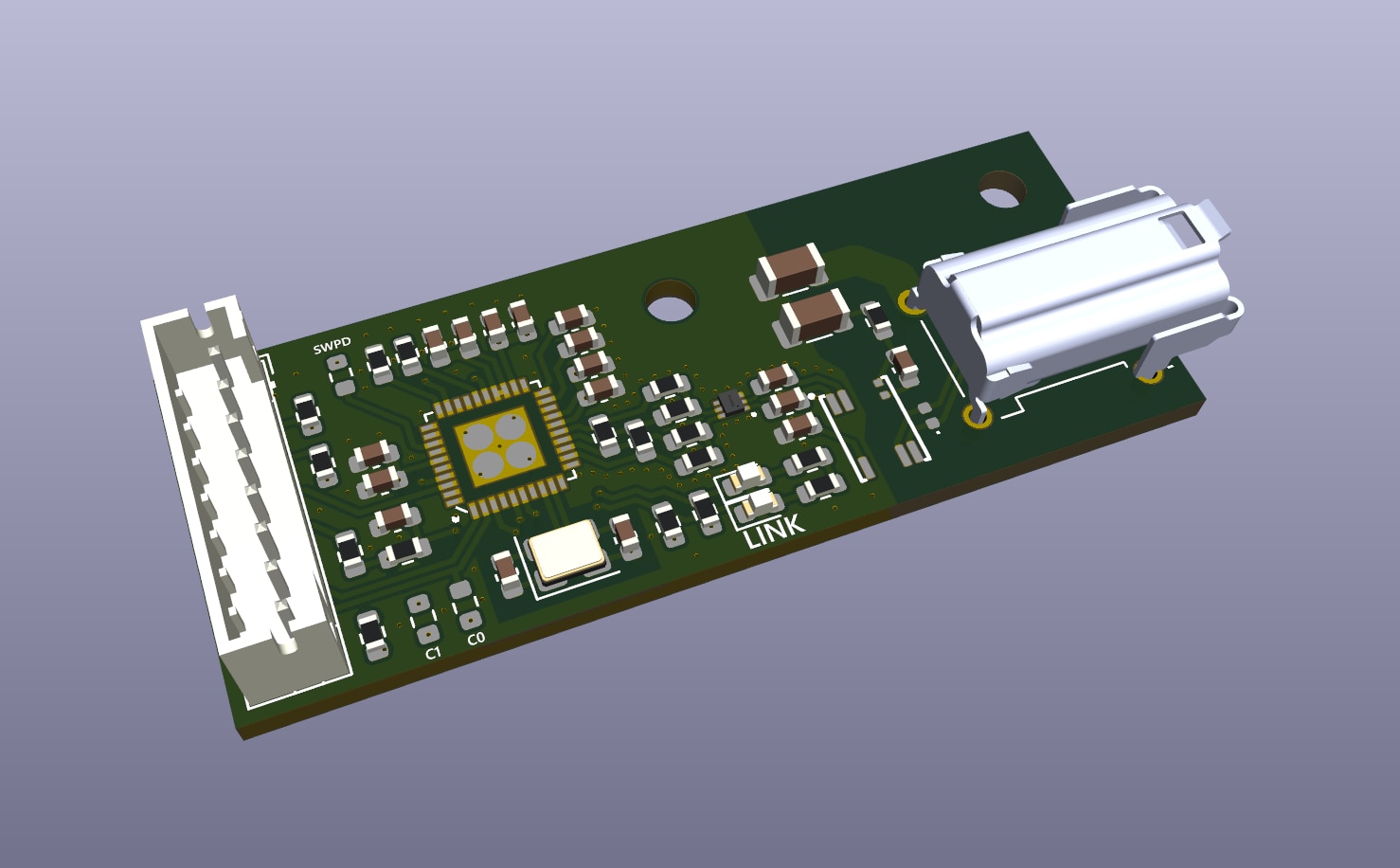
As of early March, my package with the SPE hardware just arrived, but I had to prepare for the possibility of not receiving it in time, so I also designed and ordered a custom ADIN1110 breakout board:
But back to the charger box now.
I mounted the power connectors on the side of the box. An XT90 for the charger input, and an XT90 plus XT60 for power output. The XT90 will be unused for now, but I added it for future use cases, like heaters or even a jump start lead. (my car needs less than 40A to start, the 12V system is only used to engage the traction battery contactors and run the brake pump)
I spent about 3 days wiring up everything. Most of the wires are 10mm2, with big copper lugs on them. It should be able to handle 50A with no issues.
This entire box was screwed onto the top of the battery cover, which is also thermally insulated.
An 80A MEGA fuse was added right at the battery’s positive terminal, for maximum protection.
The connectors on the wooden box were removed, as everything will be on the top plastic box from now on.
Conclusion
With the controller PCB still in a factory somewhere, I don’t have all the fancy graphs and data to show for the new charging system, as I have no way to properly communicate with the charger and SmartShunt. However, I did already test the setup, using the Bluetooth app on my phone. Everything has been perfect so far, no overheating, no instability, and no need to take the battery out of the car ever again to charge it at home.
| {gallery}Victron App Screenshots |
|---|
|
Orion XS: Overview |
|
Orion XS: Settings |
|
Orion XS: Settings |
|
Orion XS: Settings |
|
Orion XS: Settings |
|
Orion XS: Settings |
|
SmartShunt: Overview |
|
SmartShunt: Historical Data |
|
SmartShunt: Historical Data |
|
SmartShunt: Settings |
|
SmartShunt: Detailed Statistics |


