


Overview
This part is about the glovebox mounted compute unit, which is essentially the brain of the entire system.
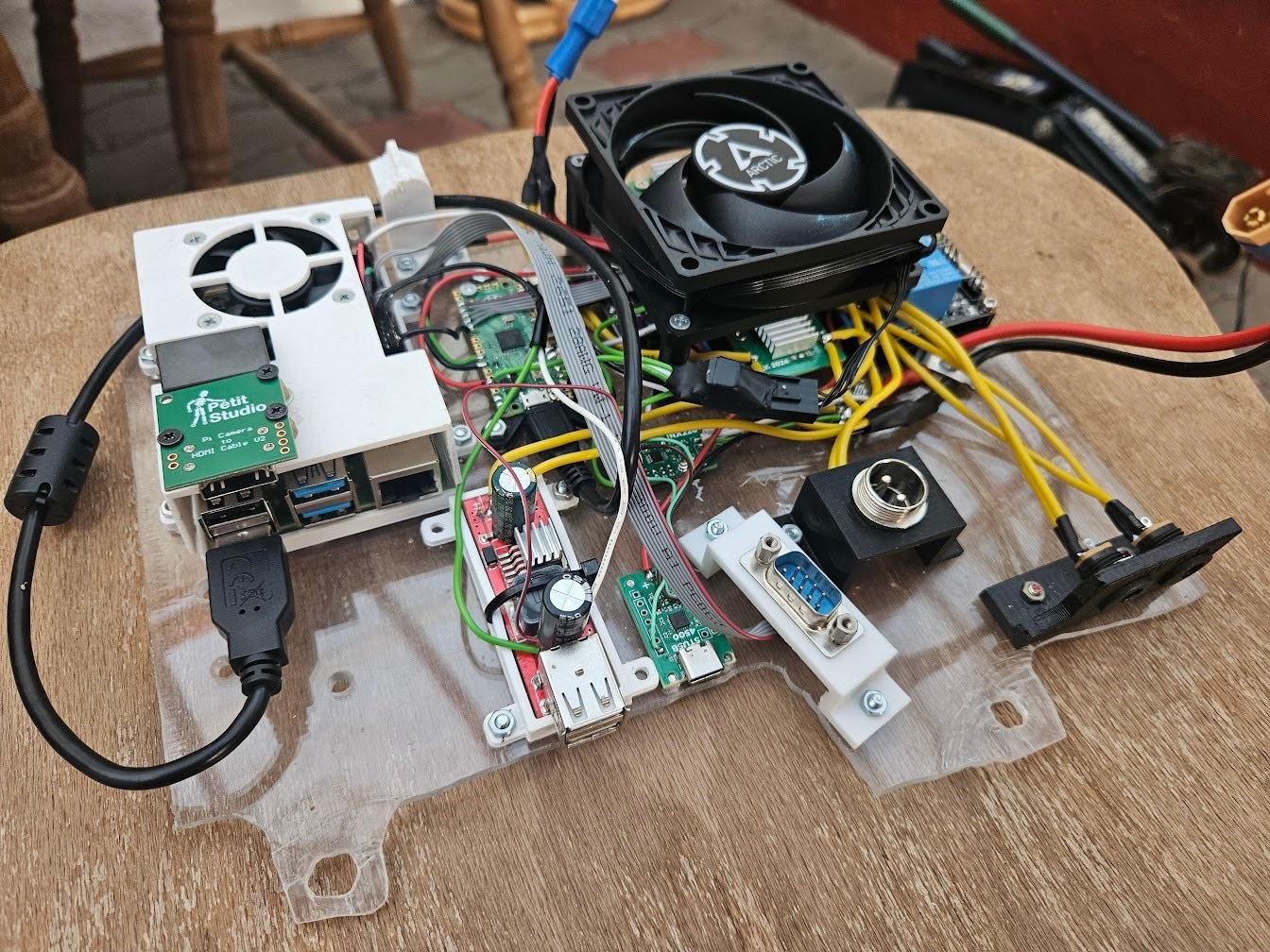
Recap of the previous setup
A Raspberry Pi 4 and Raspberry Pi HQ camera were used in this initial version. As discussed in the first overview blog, this has several drawbacks, but the biggest ones are:
- The Pi HQ Camera is bulky, has bad low light performance and dynamic range, and uses MIPI, which is a pain to wire up
- The Pi 4’s hardware H264 encoder is not particularly great
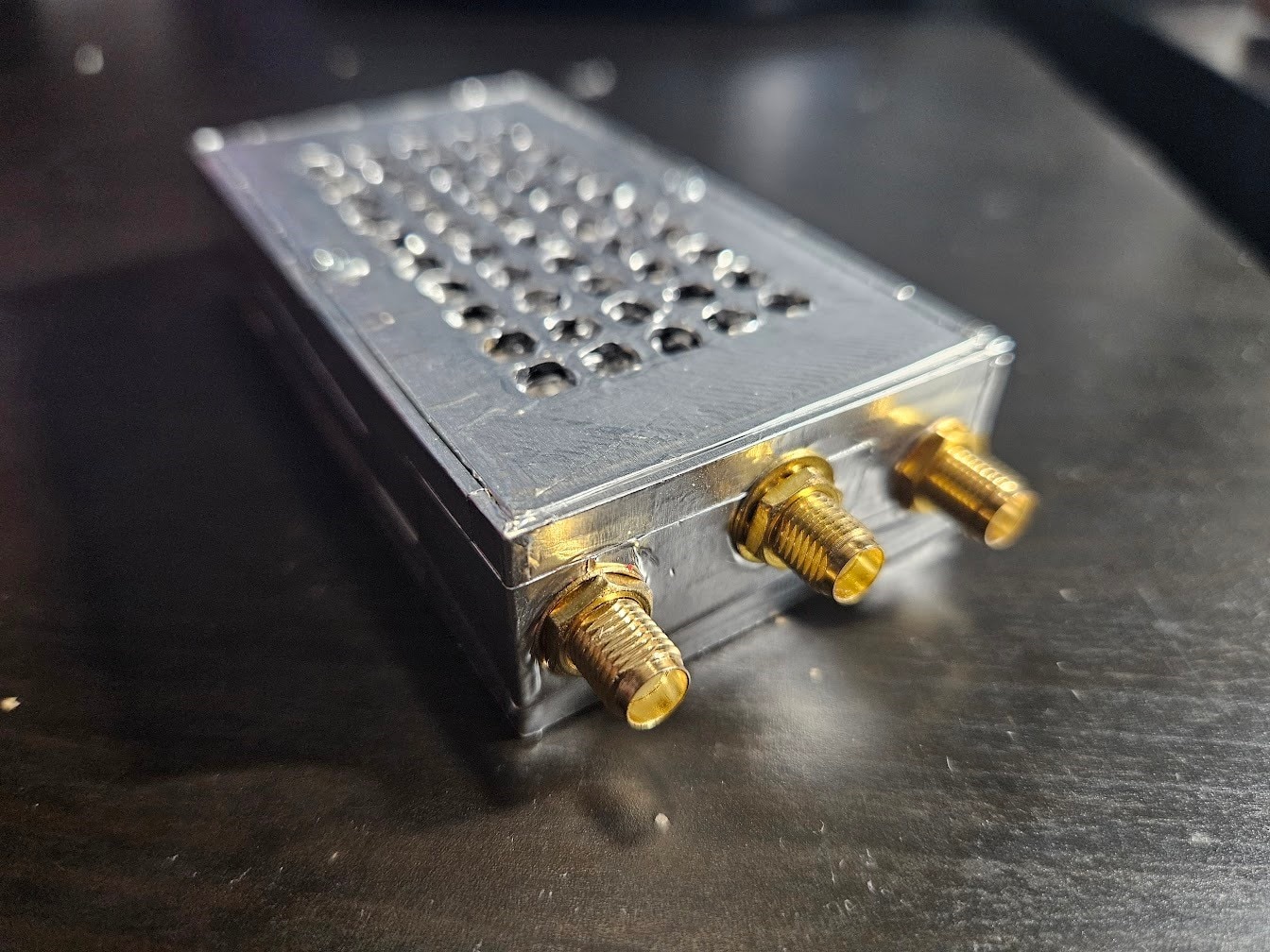
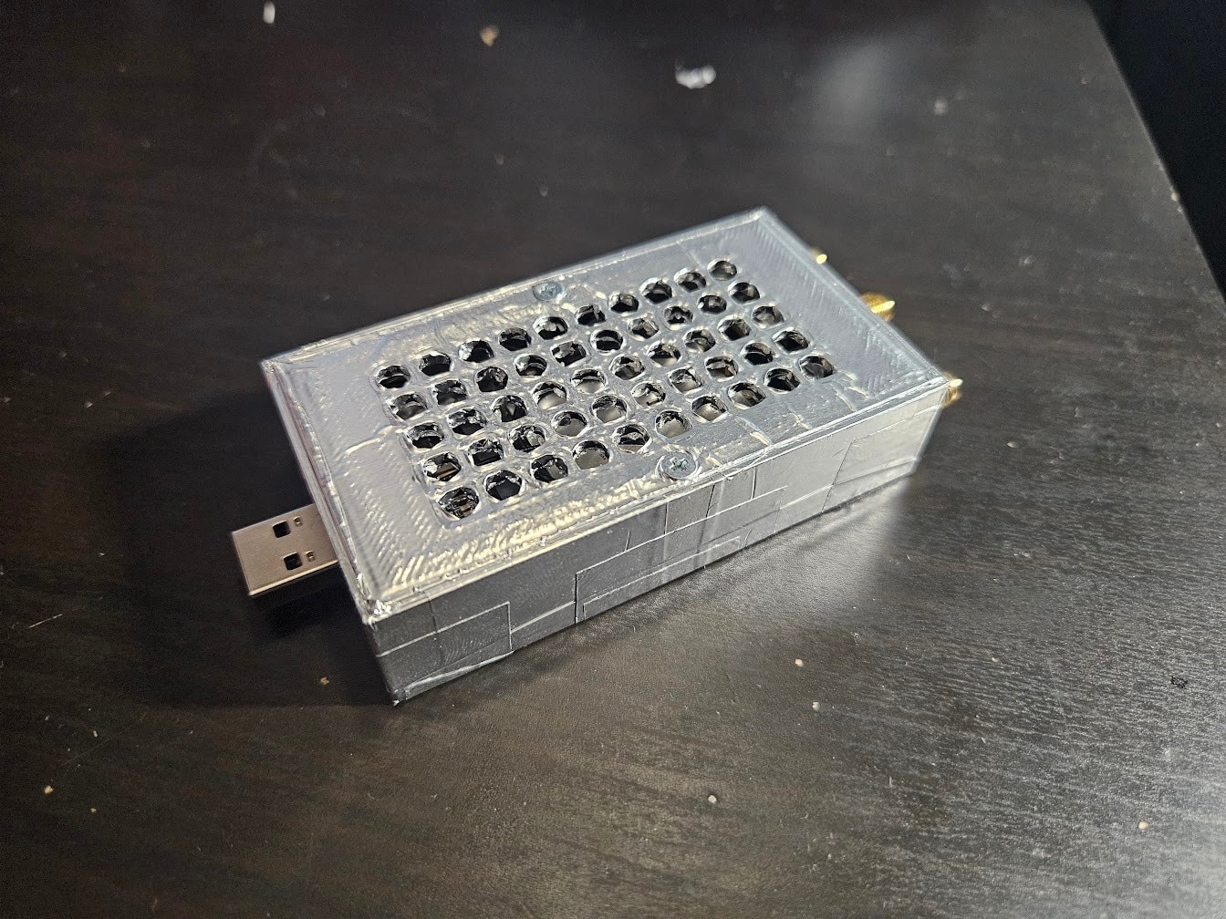
The 4G modem is also bulky, since it’s an external box on a USB cable:
The rest of the old setup was related to battery charging and management, which we already redesigned and moved to the battery unit in the last blog, so a lot of the mess can be cut out.
Planning the new system
The plan is relatively straight forward:
- Move to USB cameras
- Use a SoC with a better hardware encoder, preferably H265
- Design a custom PCB that integrates the 4G modem, power supplies, microcontroller, etc.
My first idea was making a carrier board for a Raspberry Pi CM5-style module. The CM5 itself is out due to lacking any hardware video encoders.
After some research, I came to the conclusion that the Rockchip RK3588 is the SoC I want:
- It has 4x Cortex-A76 cores, and 4x Cortex-A55 cores
- The hardware video encoder supports both H264 and H265
- There is an NPU available for neural network acceleration
There are a few Compute Module style devices available with the RK3588, but I stumbled upon the Orange Pi 5 Plus:
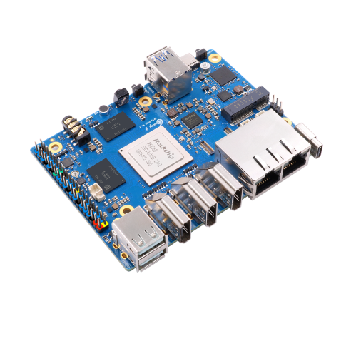
This board has all the IO I need, 2.5Gb ethernet, an M.2 slot for WiFi and Bluetooth, and a 40 pin GPIO header. I decided to make a HAT-like PCB, instead of a CM carrier board, as this would be way simpler and faster to do. There’s only a single interface that is missing from the GPIO header for this, a USB2 link to the SBC. Not a major issue, but it’s not going to be the prettiest to fix.
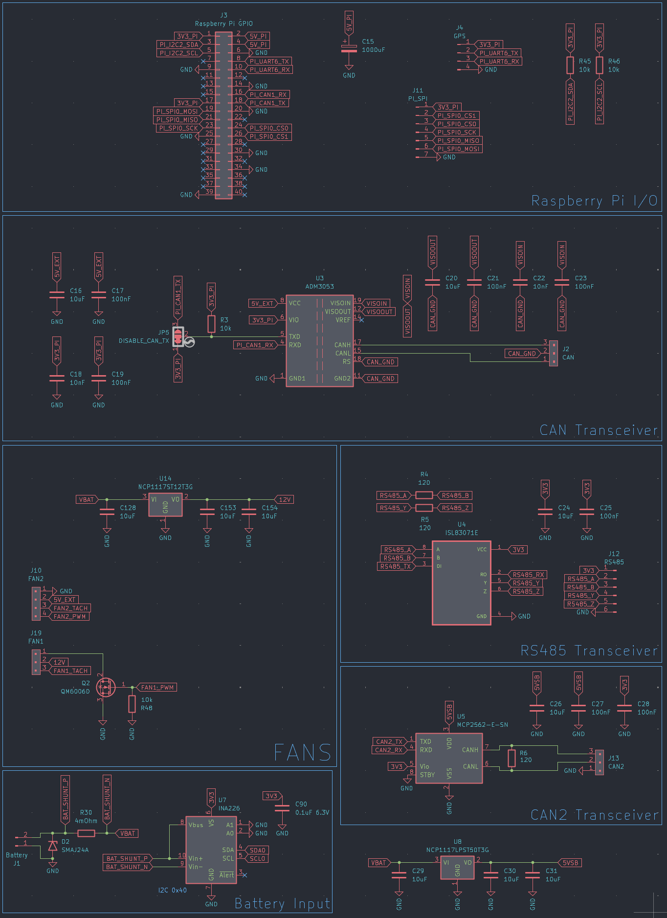
The custom HAT
I started designing the PCB. The main responsibilities are the following:
- Accept a 12-15V input source
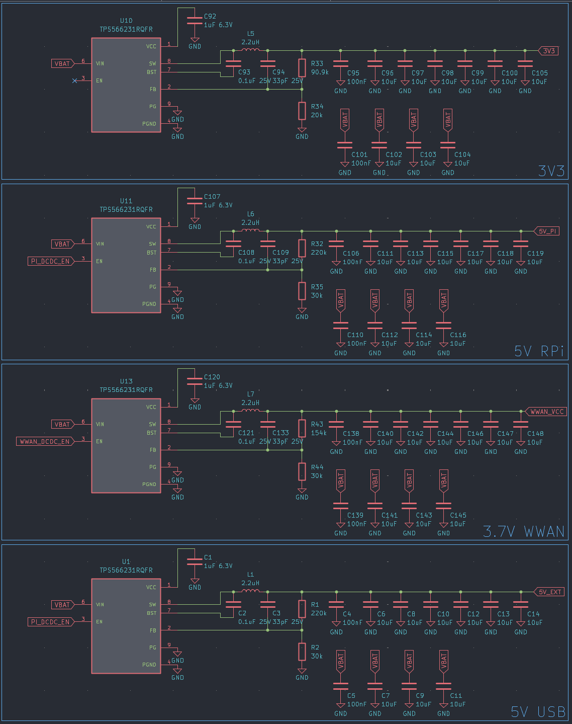
- Generate voltage rails to power the Orange Pi 5 Plus, 4G modem, and various electronics on the HAT itself
- Include a microcontroller to manage power and handle low level communication
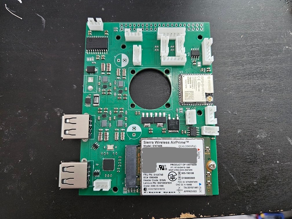
- Integrate the 4G modem
I went with TPS566231 for generating the power rails, as I used these in earlier projects and had a few left. They are high-efficiency 6A buck converters.
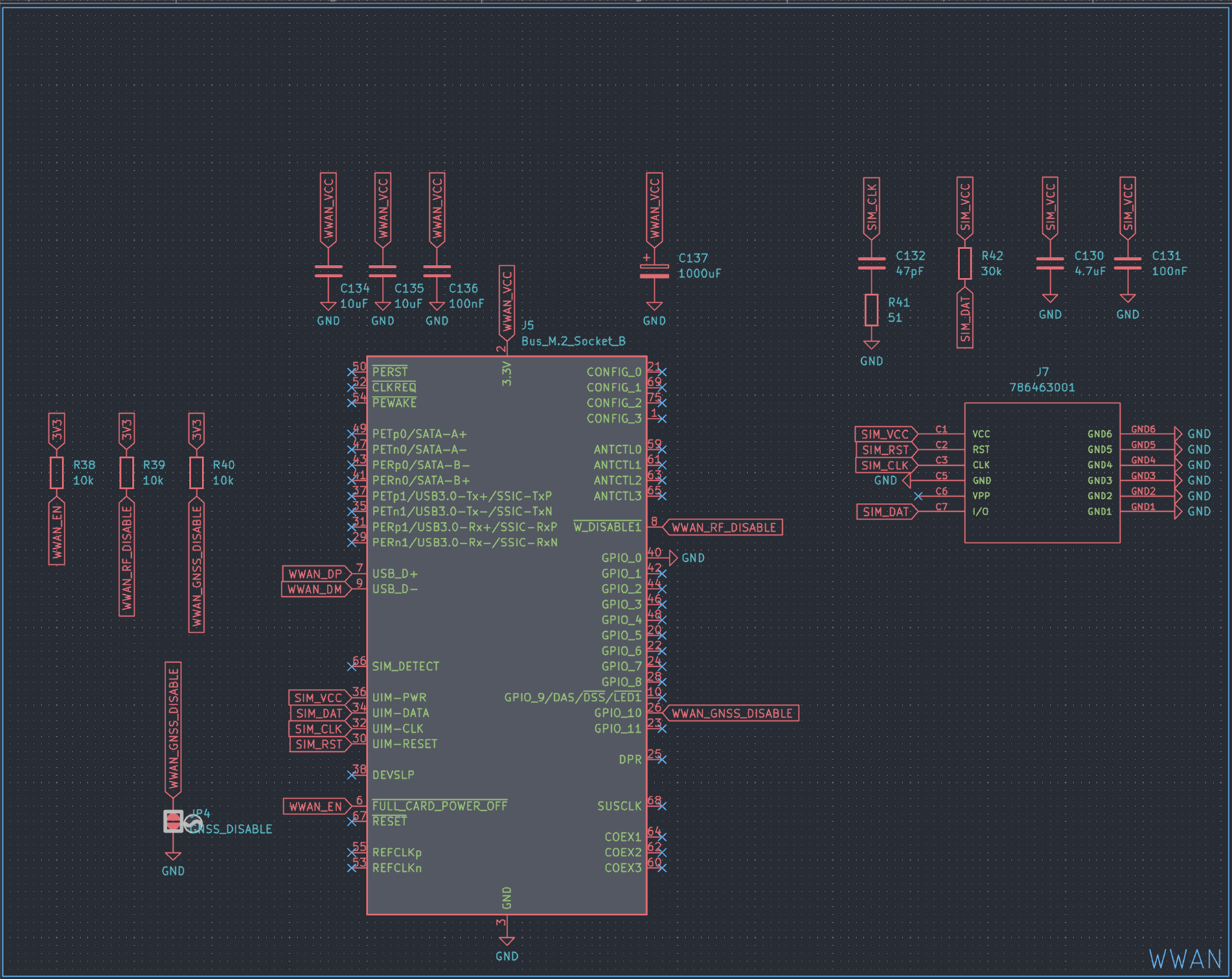
I kept the EM7455 4G modem, as there are no reasonably priced better alternatives for the moment. The next meaningful step-up would be a 5G modem, but they are around 200USD, need PCIe, 4 antennas, and are a massive pain in general. The modem itself uses an M.2 B-key connector, but we also need a SIM card slot. The modem supports USB3, but USB2 will be plenty for us.
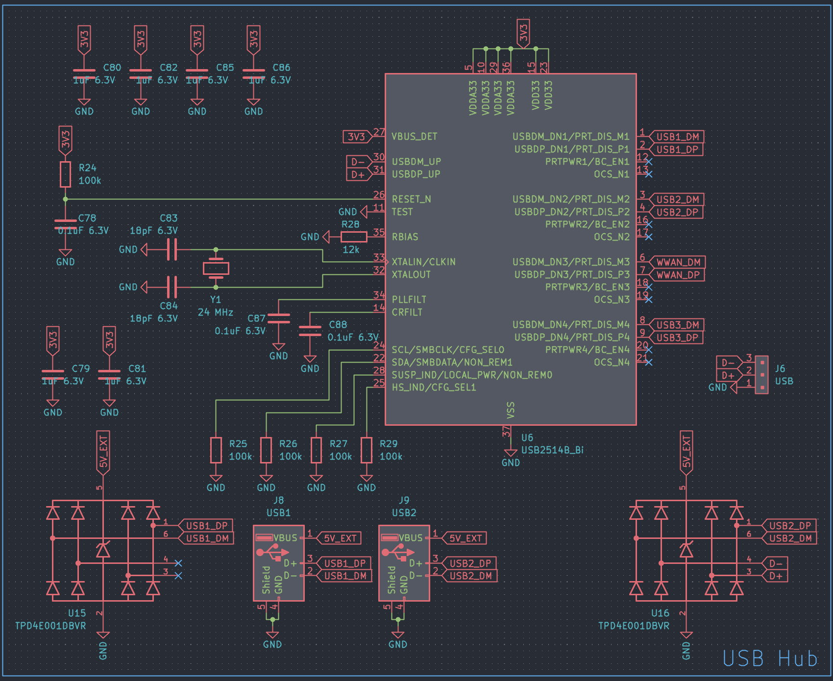
Since I need to attach both the ESP32 and modem to the Orange Pi through USB, I added an onboard USB hub, a USB2514B to be specific.
As it’s a 4 port hub, and we only need two, I decided to expose the two remaining ports for miscellaneous stuff I could need later.
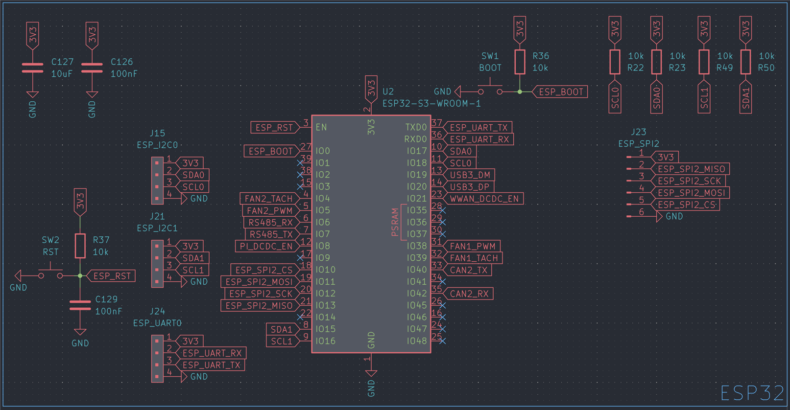
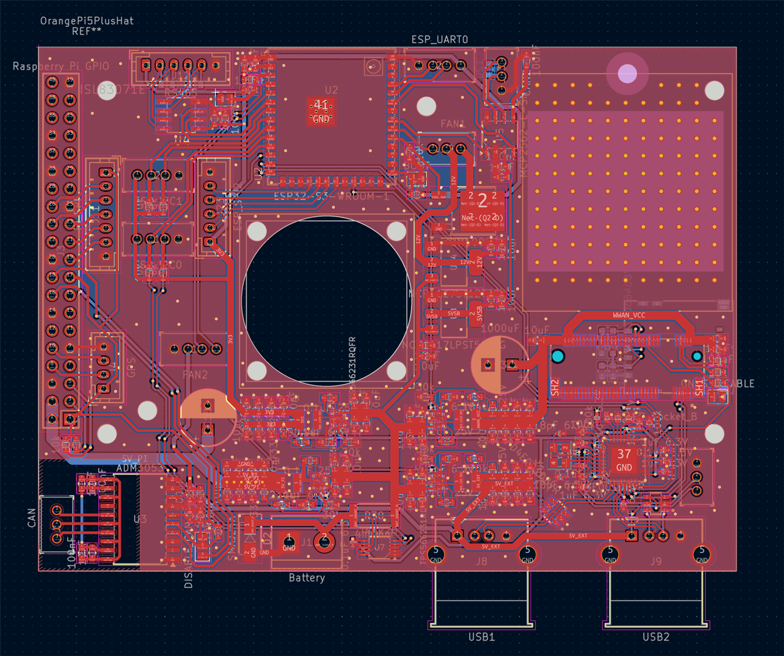
An ESP32-S3 was chosen for the microcontroller, more specifically an ESP32-S3-WROOM-1U
I also added a fully isolated CAN transceiver, so I can later hook this up to my car’s CAN bus network, and a second, non-isolated CAN transceiver, along with full-duplex RS485 for future expansion.
An INA226 was included to monitor power consumption, added some fan headers and FETs to control them, and that’s about it.
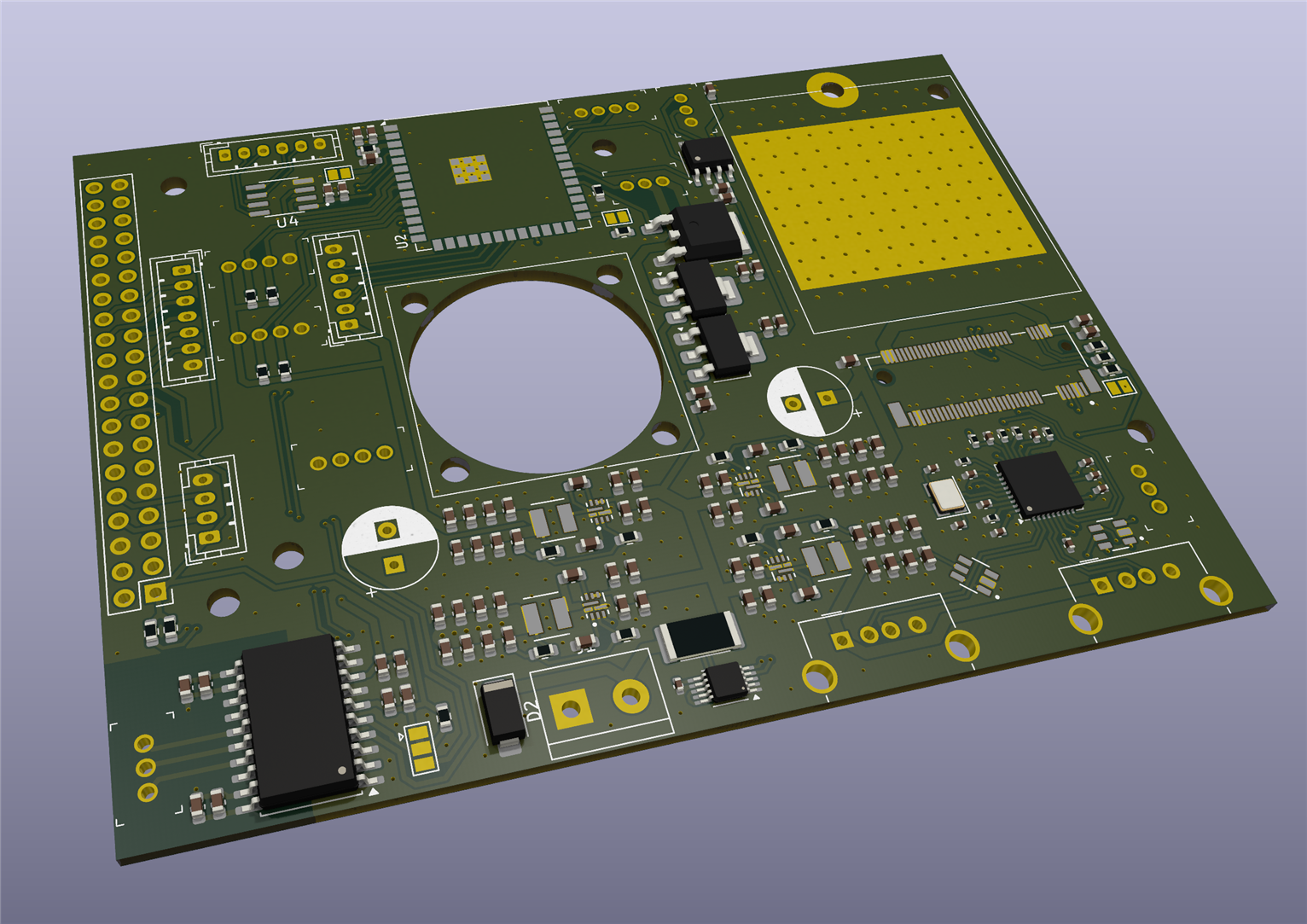
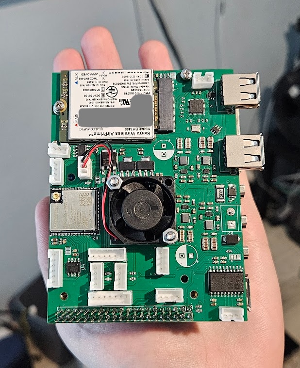
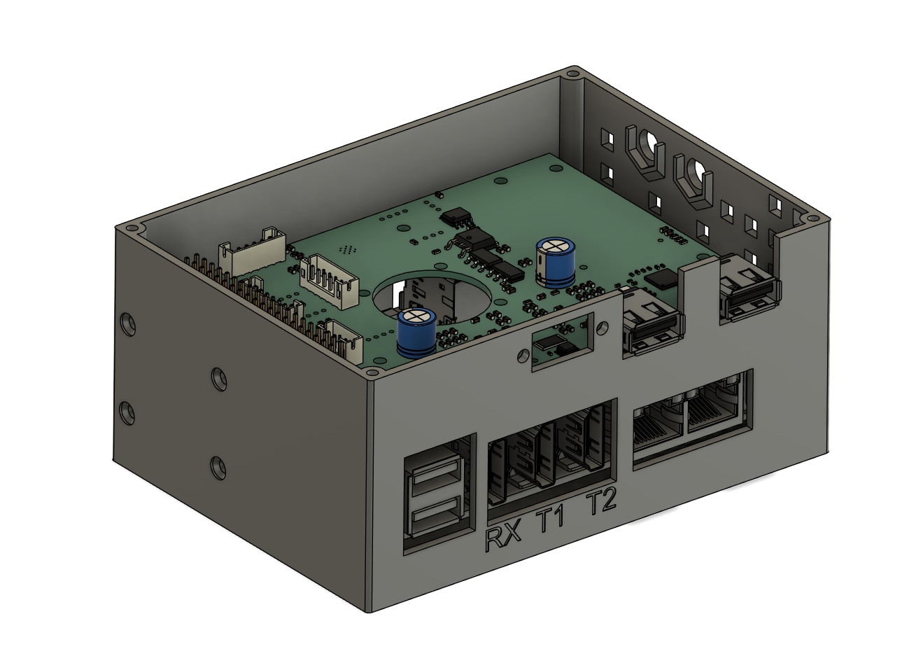
I squeezed the design into a 100mm x 75mm form factor, the exact size of the Orange Pi 5 Plus.
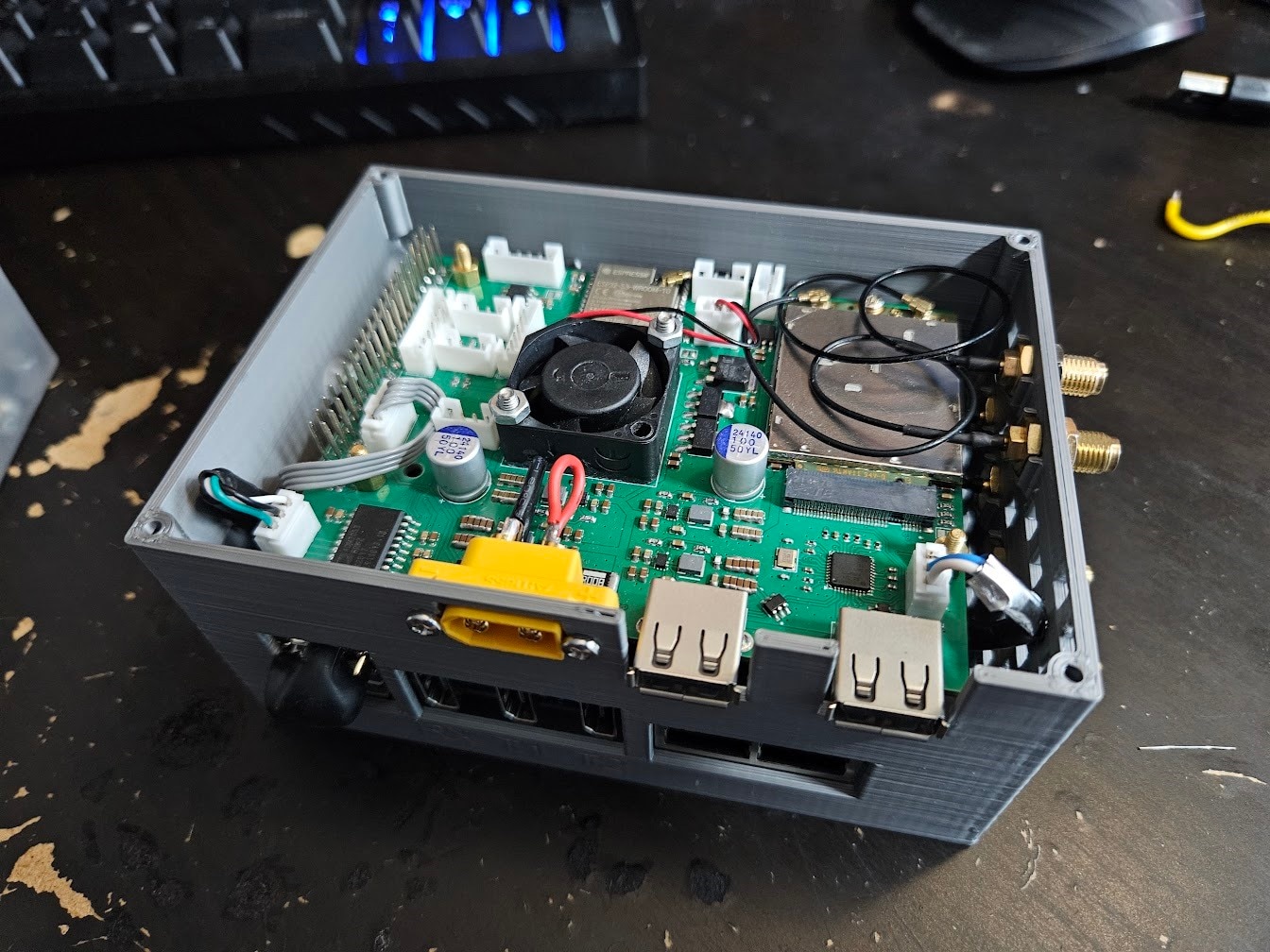
The hole in the center is for a tiny 25mm x 25mm fan, to provide some airflow to the SoC, directly below, and also cool the modem.
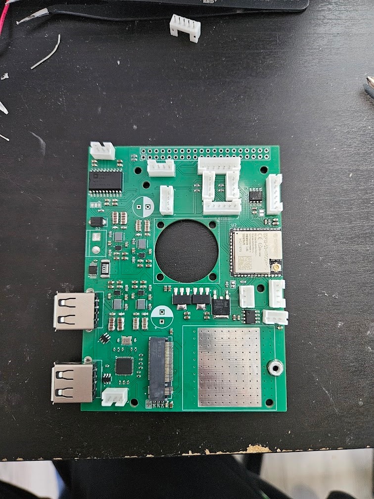
I ordered all the parts, along with the 16GB RAM version of the Orange Pi 5 Plus (right before the RAM apocalypse, so I still have all my organs intact).
Assembly
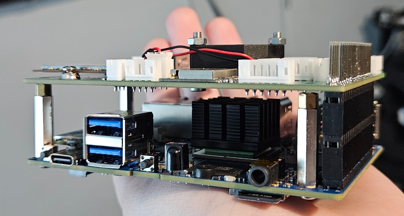
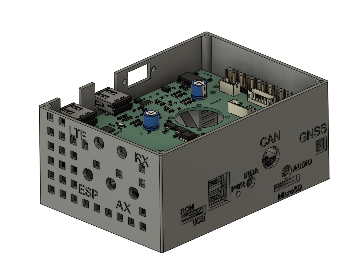
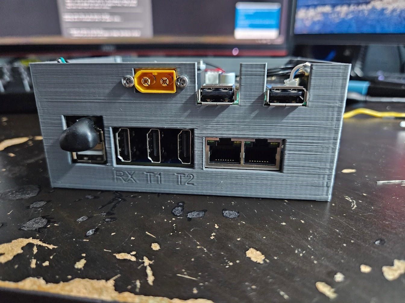
I bought an Intel AX200 WiFi+Bluetooth card, and also got a Ublox Neo M8N GPS module. I whipped up an enclosure in Fusion for the entire thing:
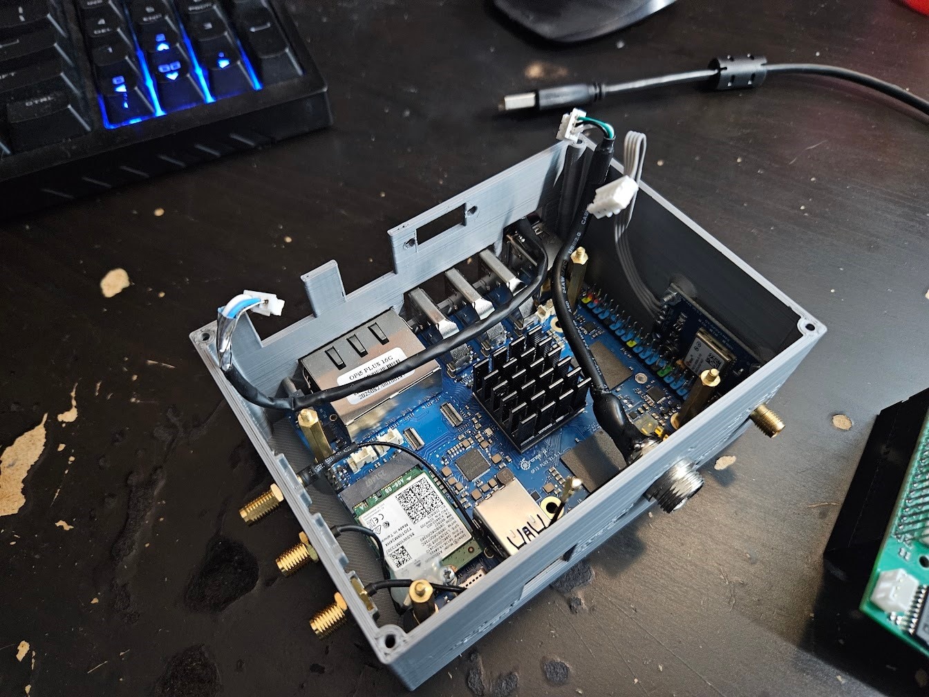
The USB2 connection to the HAT was made with a custom cable that I plugged into one of the USB2 ports on the Orange Pi 5. It’s not the prettiest, but it works well.
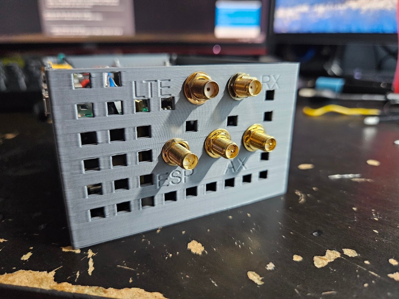
You might ask yourself, where’s the SPE stuff? Well, at the time of making this, I didn’t have any of it yet, so I just made sure to add a bunch of extra IO and expansion ports to the PCB. The enclosure was made in a way to have another relatively large compartment screwed to the top, which will house the SPE transceiver and MAC.
Conclusion
I installed Armbian on the Orange Pi 5 Plus, wrote some minimal code for the ESP32 to enable all the buck converters, and set up a simple low battery voltage cutoff feature.
So far, everything has been working great, and I’m very happy with the Orange Pi 5 Plus,
With the Compute Unit ready, the next post will be a shorter one, about finding the perfect camera modules for our use case, and wiring them up.


