Hello everyone. In this blog post, I will describe measuring large (super)capacitance using Raspberry Pi, Python, and a few cheap and simple parts. Python running on Raspberry Pi will be used for controlling the measurement circuit and computations. Except these, no expensive test equipment will be required which makes this approach interesting (at least to me). I wrote this blog as part of Experimenting with Supercapacitors. In this blog, I will describe the methodology that allowed me to successfully measure supercapacitors without using any expensive equipment. In the next blog, I will describe the unsuccessful approaches that I tried before. I will simplify a lot of descriptions in this blog to make it shorter. If you do not understand something, then feel free to ask in the comments at the bottom of the page.
Measuring Large Capacitance
Measuring small capacitance in a range from tens pF to hundreds of uF is easy because nowadays digital multimeter (DMM) supports this kind of measurement, but the approach used by DMM is suitable only to the scale of lower hundreds of uF and even if you try it, you may notice that these measurements are slow. But supercapacitors have capacitances in a range from tenth to hundreds of Fards. For example, 1F which is considered a low capacitance of supercapacitor is 1000x more than 100uF which is high capacitance in terms of standard electrolytic capacitors. Measuring so high capacitance requires a special technique. This technique is well described in the Technical Guide which is available to download at Cornell Dubilier’s website. The technique is based on expressing capacitance from the formula from Wikipedia:

The function of current is replaced by constant because constant current source and sink are used and derivation is replaced by “engineering real-world implementation of derivation”, ie. by differentiating two points, their corresponding values and dividing. The modified formula helpful for measuring large capacitance (not only using Python) from CDE document is the follows:

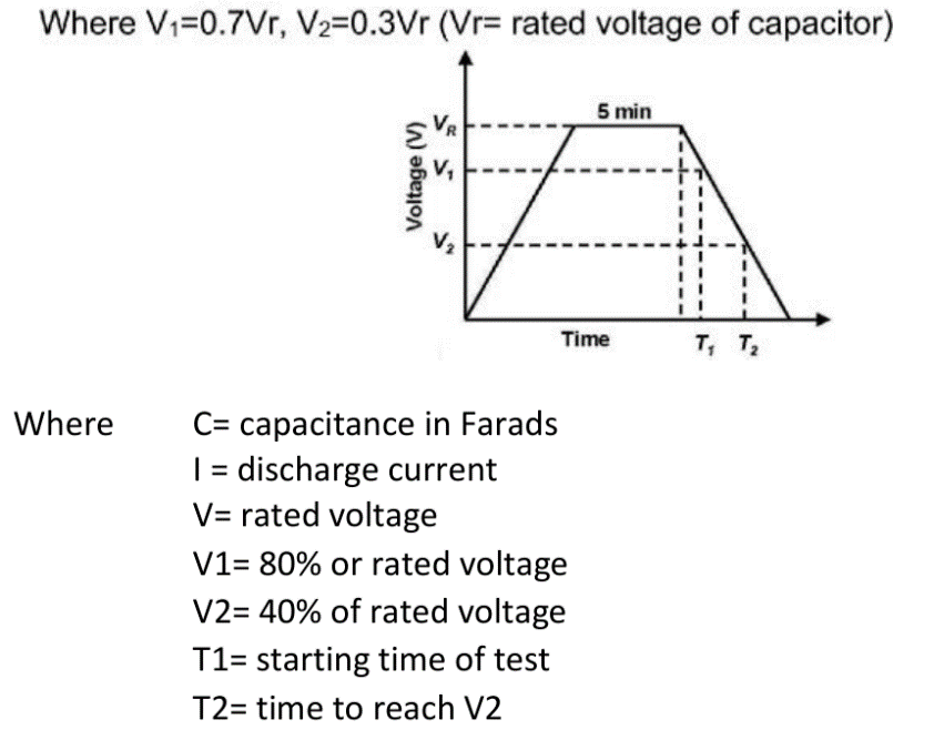
The strategy of measuring capacitance is by selecting two voltages V1 and V2 (0 < V2 < V1 < rated voltage of supercap) and measuring how long it takes to discharge (or charge) from between V1 and V2 when discharging/charging capacitor between its rated voltage and zero. To eliminate capacitor leakage, it is recommended to keep the capacitor powered for some time before discharging (it will consume little current which will decrease over time). It is highlighted in the CDE document by the following chart and legend.

Note that the CDE description and recommendation are slightly confusing because in the description they recommend different values (for example, coefficients 0.7 vs. 0.8, 0.3 vs. 0.4, 5 min vs. 30 min).
Measuring circuit
For measuring you need a circuit that will charge your capacitor and a circuit that will discharge the capacitor. Normally you use a power supply with support for constant current mode for charging the capacitor and an electronic load (with support for constant current mode) for discharging the capacitor. But these are expensive tools and I currently do not have any of them. Alternatively, you can use a Source Measurement Unit (SMU) which supports both modes in one device, but unluckily, it is an even more expensive device. For this reason, I had to replace these tools. I tried several techniques and most of them I will describe in the next blog (describing unsuccessful ways). Here I will show the successful way.
LDO as a Constant Current Source
The technique which I will describe is not invented by me. Instead, I found it Analog Devices (originally Maxim Integrated) application note 4404: Using a Linear Regulator to Produce a Constant Current Source. This article contains a more detailed analysis of this technique. Here I will describe it only basically.
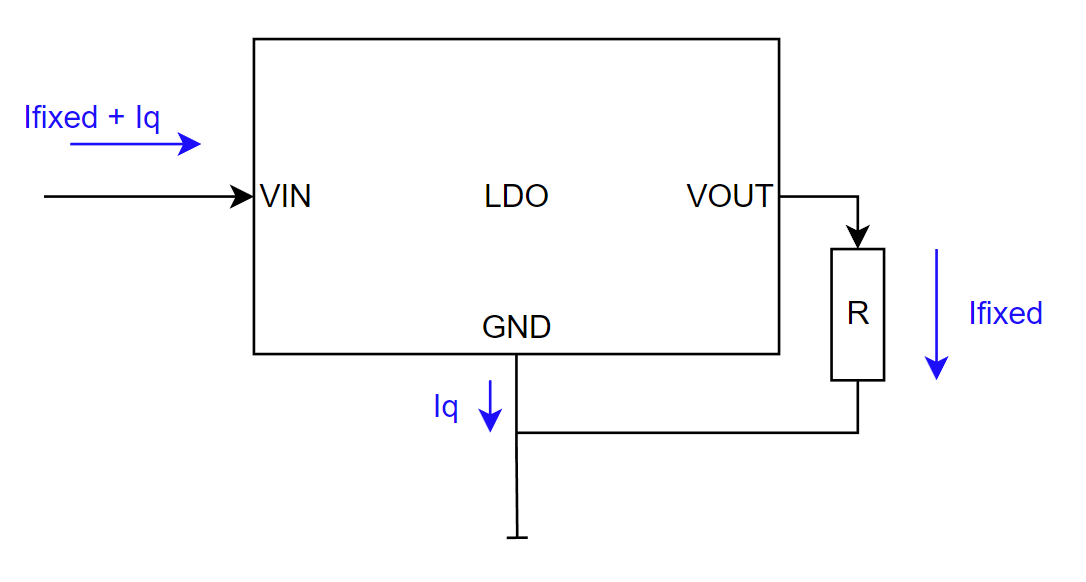
The idea is that smartly connected LDO voltage regulator can work as a constant current source. Normally, LDO works as a constant voltage source but can be quite easily connected to make a constant current. The idea is that the ground of that LDO is not connected to the circuit ground, but it is connected to the (positive terminal of) loaded device. The output of the LDO is loaded by the resistor. Since the voltage difference between LDO GND (which is not GND of the whole circuit) and LDO VOUT is driven to be fixed and resistance is also fixed, the current flowing through the resistor is also fixed. Additionally, one of the properties of LDO is that the input current is almost equal to the output current which means that the current flowing through the circuit is almost fixed, and it is constant no matter of real load connected between LDO GND and real GND of the circuit.

The circuit has some limitations. For example, it is limited that the maximum voltage applied to the load is VIN minus the output voltage of LDO. If the load requirement exceeds this limit, then LDO will not act as a constant current source anymore. This limitation is beneficial for my application because it allows me to set the voltage limit. There is also the impact of dropout voltage, which is dependent on the output current, but since the output current is fixed, it is easy to evaluate and deal with it.
LDO as a Constant Current Sink
Similarly, LDO can be used as a constant current sink. After reading previous the paragraph it should be easy to realize it. If LDO is loaded by a fixed resistor, its input current is defined by LDO output voltage and attached fixed resistor. It is a standard LDO connection with a resistor load.

Like the previous case, there are some restrictions which are now more significant. The constant current load does not work if the voltage is below the output voltage of LDO. So for example, if you have 1.8V LDO, it will not work as a constant current sink when the input voltage is below 1.8V (+ dropout). This restriction limits me when discharging the capacitor. After discharging to this level, LDO as a constant current sink is unable to discharge the capacitor anymore. The workaround is to use LDO with as low an output voltage as possible. In opposition when measuring lithium-ion capacitors (LIC) we need to prevent over-discharge capacitors and this limitation can assure this quite a well (note that even below output voltage level, it still passes little current, so do not consider it as an ultimate solution).
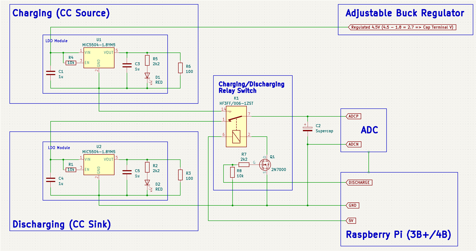
Connection

The two circuits described above I interconnected. For selecting a source or a sink I used a relay. In the ultra-low-cost variant, you can eliminate this relay and update it with a transistor or even the lower-cost variant excludes the switch completely and manually switch wire after the script writes “Discharging” on its output. Temporary disconnection will not influence results because measurement begins at 0.8 of rated voltage, so before you swap the wire the charged supercapacitor will not drop below this threshold. Raspberry Pi needs to measure the voltage of the supercapacitor. I used MAX11410 24-bit precise ADC on my own PCB, but you can use any ADC you want. A higher resolution is better. Since charging and discharging are slow, the sample rate is not very important. (Mine has only 1.9ksps and the library is unoptimized, so it is about 0.4ksps). You will need to update the measurement Python script with code related to your ADC if you decide to use a different ADC. Finally, there is a buck regulator used as a source for LDO based constant current generator. The output voltage of this regulator must be set to the rated voltage of the measured capacitor plus the output voltage of the constant current source LDO (1.8V in my case). If you set it lower, nothing will happen, but the supercapacitor will stop charging at a lower level and the script will never end. You can adjust it when charging is in progress. If you set it too high, then you risk destroying your capacitor. The script will detect it and when the voltage reaches the termination voltage it will switch the relay to discharge mode, print an error and terminate. There is some dropout by the LDO CC source, but I still recommend setting the voltage at 0.1V lower compared to the termination voltage. The script accepts 0.2V.
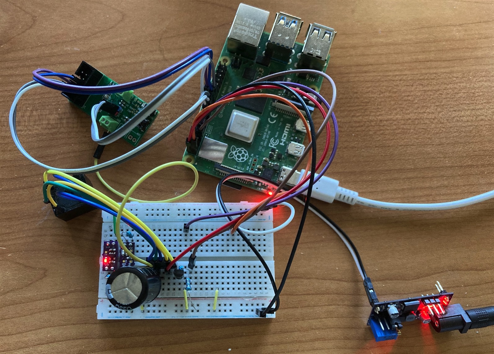
In the real world, connections look as follows. Most of my interconnections are on the breadboard. The green board near Raspberry Pi is my ADC module and the black box with wires attached to the breadboard is a relay. LDOs are on the modules on the left side of the breadboard. The last board in the bottom right corner of the first photo is my step-down module which converts 12V to voltage adjusted by a potentiometer depending on the rated voltage of the tested capacitor.


Before I start describing Python script, I want to spend some time with one accuracy detail.
Accuracy
As designed, the circuit is not accurate due to several sources of inaccuracy. The largest inaccuracy is caused by the R3 resistor. Discharge current is directly exposed in the measurement formula. Even if you use a precise 100 ohm resistor, the constant current sink is not exactly 18mA (computed using ohm law I = V / R; I = 1.8 / 100). At first, the resistor has some tolerance. Additionally, resistance is quite low, so the circuit is sensitive to additional resistance of wires, especially in the case of breadboard setup. An additional source of inaccuracy is that current is not only defined by the resistor R3, but also by quiescent current (Iq) of LDO, but modern LDOs have low Iq, so it is not a big issue, but a similar bigger issue is that my LDO modules have LED connected to output. So, the constant current is the sum of Iq, current flowing through the resistor and current flowing through the LED. All these factors are affected by inaccuracy. For this reason, I do not rely on actual current. Instead, I measured the real current using an amperemeter and in the Python script I did not used 18mA, but instead I use 18.95mA which is the current which I measured.
The same happens on the constant current source side, but because capacitance is measured at the discharge phase, we do not need to worry about charging current inaccuracy much.
Wires between circuits and capacitors efficiently increase the ESR of the capacitor, but it does not influence this measurement (in the case of ESR measurement, it of course does).
Because I use a relay instead of transistors there are no leakages, but there is still additional series resistance, which is not a big issue as mentioned in the previous paragraph.
Lastly, there is the inaccuracy of time measurement and especially jitter caused by non-deterministic ADC handling in Linux user space. But because measured times are long (tens of seconds to minutes) it should not cause any serious issues.
5.5V Supercapacitors
The last hardware caveat is that the circuit is limited to capacitors with rated voltage up to 3.3V because more than 3.3V is outside range of the ADC and increasing furthermore will burn it. The initial idea was to use a simple voltage divider, but it has one drawback. It is a load on the capacitor which adds parasitic current. It has the largest impact in the discharge phase when measuring the time of discharging. A better solution is to use an operational amplifier configured as a follower (unity gain) and a connecting voltage divider on its output. Depending on used operational amplifier there still may be some limitations. For example, when powered from Raspberry Pi 5 volts, you will not be able to measure at the full 5.5V scale, but it should be still sufficient. At last, it is important to remember the compensating added divider in the Python script.

Measuring capacitors over 5.5V is impossible with the current circuit because discharge LDO is limited to 5.5V on input.
Python script
Download: capacity4.py
Python script is very simple (~120 lines of code). Requirements are spidev and GPIO library. GPIO library is used for controlling relay and SPI is used for communicating with ADC. By default, the pin for triggering the relay is GPIO4. The script has a few constants which you need to set before starting and adjusting before every run. VTERM is the most important variable. Should be set to the rated voltage of the capacitor. It is the voltage which is written on the capacitor body. An additional important constant DISCHARGE_CURRENT, which defines Current in amperes which is used for discharging capacitors. In theory, it should be 18mA if connected as described in the hardware section above, but I recommend measuring it and writing real value for compensating several inaccuracy sources. You can of course use different current. CDE recommends 10mA per every Farad of the measured capacitor. So, for example, for measuring a 1F capacitor you should use 10mA. Additional two constants are used for setting voltages between which the script is measuring capacitors. It is the V1 and V2 from the CDE guide mentioned at the beginning of the script. The preferred (but not used by me currently) way is to use 0.8 and 0.4 coefficients which automatically set optimal points based on the capacitor’s rated voltage. I currently do not use it because my lowest output voltage LDO is 1.8V LDO which means that my circuit can’t discharge capacitor below 1.8V (by drawing constant current). For this reason, I had to update limits and instead of multiplication of rated voltage with 0.4 and 0.8 I used different constants which are suitable to work with 1.8V LDO. It is better to use 0.4V, 0.6V or 0.8V LDOs instead. They are available on the market, but I currently have none of them in my lab. DELAY constant is used for specifying the duration between the charge and discharge phase. CDE document is confusing on this. In the text they mention 30 minutes, in the diagram, they mention 5 minutes. By default, the script uses 5 minutes. Finally, there is a VCC constant used for specifying the reference of ADC. In my case, it is 3V from Raspberry Pi, but I measured it as 3.315V and used it for compensating inaccuracy. Replace it with the reference voltage of your own ADC.
First, the script initializes and configures ADC. The next step is charging the capacitor. In this phase script enables charging by switching the relay and continuously measuring voltage which it prints to the console. It checks for violating of rated voltage and also checks for reaching a voltage 0.2V below rated voltage. In case of violating rated voltage, it disables charging and print error. In case of reaching boundary 0.2V below the rated voltage, it assumes that the capacitor is charged and continues to the next phase. As mentioned in the hardware description above, you should set the voltage regulator to 0.1V below the rated voltage which satisfies the script requirements and adds adequate tolerance. The second phase is the delay phase. In this phase capacitor voltage does not increase but is still powered, at this phase capacitor reduces its leakage. In this phase program just monitors voltage and checks for violating rated voltage. If everything is ok, this should not happen. In this phase program still prints and continuously updates the voltage on the console window. Finally, the third phase is most interesting. Program switches relay and capacitor start discharging. The program continuously monitors voltage and saves timestamps when the voltage drops under configured voltage thresholds V1 and V2 as used in the CDE document. After the capacitor voltage drops below both levels, the program terminates and computes capacitance using an equation from CDE documents. At the end, it prints measured capacitance.

Evaluation
The circuit and script I successfully used to validate the capacity of capacitors, except lithium-ion capacitors. I will evaluate them later after I receive the new adjustable LDO, and I will publish the results in the final blog. DGH and DSF family capacitors I tested with circuit the same as presented in this blog post. For both families, I set VTERM 0.1V below the rated voltage of capacitors (ie. 2.6V in the case of DGH and 2.9V in the case of DSV). As described above, I adjusted V1 and V2 voltages between which the time is measured. I used measured capacitance when discharging between 2.5V and 2.0V in the case of DGH caps and between 2.6V to 2.1V case of DSV caps. The discharge current was 18.95 mA in all cases. I measured the following results:
|
Capacitor |
Expected C |
Measured C |
Deviation |
Tolerance Min |
Tolerance Max |
Result |
|
DGH105Q2R7 |
1 |
1.126 |
+12.6 % |
-10 % |
+30 % |
PASS |
|
DGH505Q2R7 |
5 |
6.047 |
+20.9 % |
-10 % |
+30 % |
PASS |
|
DGH106Q2R7 |
10 |
12.204 |
+22.0 % |
-10 % |
+30 % |
PASS |
|
DSF305Q3R0 |
3 |
3.222 |
+7.4 % |
-10 % |
+30 % |
PASS |
|
DSF705Q3R0 |
7 |
8.387 |
+19.8 % |
-10 % |
+30 % |
PASS |
|
DSF256Q3R0 |
25 |
31.589 |
+26.4 % |
-10 % |
+30 % |
PASS |
Most coin capacitors are 5.5V rated, so I need to update my circuit by adding a buffer (operational amplifier) and resistor divider as described above. There is one exception that requires special care. EDS224Z3R6H is rated to 3.6V while all other parts in EDS and EDC families are 5.5V rated. 5.5V rated capacitor I charged to 5.3V and measurement was done according to recommendation between 40% and 80% of rated voltage, thus between 4.4V and 2.2V. In the case of the 3.6V unit, I charged it to 3.5V and measurement was done between 2.8V and 2.2V, similar to DGH and DSF families. In all these cases discharge current was 3.59 mA which is lower because capacitances are lower than in previous cases. I measured the following results:
|
Capacitor |
Expected C |
Measured C |
Deviation |
Tolerance Min |
Tolerance Max |
Result |
|
EDS104Z5R5C |
0.1 |
0.118 |
+18.1 % |
-20 % |
+80 % |
PASS |
|
EDS224Z3R6H |
0.22 |
0.290 |
+32.2 % |
-20 % |
+80 % |
PASS |
|
EDC474Z5R5C |
0.47 |
0.398 |
-15.2 % |
-20 % |
+80 % |
PASS |
|
EDC105Z5R5H |
1 |
1.132 |
+13.2 % |
-20 % |
+80 % |
PASS |
In almost all cases measured capacitance was higher than the capacitance written on the package which I expected from the CDE caps. The only exception in my case is the 0.47F unit. I measured it using the same conditions that I used for measuring 0.1F and 1F units, but in all multiple attempts, I measured capacity between 0.38F and 0.42F which is lower than expected 0.47F. The value mentioned in the table is my first measurement. But even if the real value is lower, it is still within the specified tolerance range.
Conclusion
And now we are at the end of this blog. The main purpose was to show a low-cost technique for measuring the capacitance of supercapacitors. It is not a surprise that Cornell Dubilier’s high-quality capacitors which I work with all passed the test. My experiments are currently partially blocked because of waiting for some PCBs, but I will soon start to continue my journey as described in my Introductory blog. In the meantime, I will publish the second part of this blog. In the next blog, I will describe paths that I tried before ending up with two LDOs used as constant current source and sink. Thank you for reading this blog and stay tuned to my next blogs!
Next blog: Measuring Capacitance using Python Part 2 (the unsuccessful ways)

