element14 Community
element14 Community
    Register Log In
  • Site
  • Search
  • Log In Register
  • About Us
  • Community Hub
    Community Hub
    • What's New on element14
    • Feedback and Support
    • Benefits of Membership
    • Personal Blogs
    • Members Area
    • Achievement Levels
  • Learn
    Learn
    • Ask an Expert
    • eBooks
    • element14 presents
    • Learning Center
    • Tech Spotlight
    • STEM Academy
    • Webinars, Training and Events
    • Learning Groups
  • Technologies
    Technologies
    • 3D Printing
    • FPGA
    • Industrial Automation
    • Internet of Things
    • Power & Energy
    • Sensors
    • Technology Groups
  • Challenges & Projects
    Challenges & Projects
    • Design Challenges
    • element14 presents Projects
    • Project14
    • Arduino Projects
    • Raspberry Pi Projects
    • Project Groups
  • Products
    Products
    • Arduino
    • Avnet Boards Community
    • Dev Tools
    • Manufacturers
    • Multicomp Pro
    • Product Groups
    • Raspberry Pi
    • RoadTests & Reviews
  • Store
    Store
    • Visit Your Store
    • Choose another store...
      • Europe
      •  Austria (German)
      •  Belgium (Dutch, French)
      •  Bulgaria (Bulgarian)
      •  Czech Republic (Czech)
      •  Denmark (Danish)
      •  Estonia (Estonian)
      •  Finland (Finnish)
      •  France (French)
      •  Germany (German)
      •  Hungary (Hungarian)
      •  Ireland
      •  Israel
      •  Italy (Italian)
      •  Latvia (Latvian)
      •  
      •  Lithuania (Lithuanian)
      •  Netherlands (Dutch)
      •  Norway (Norwegian)
      •  Poland (Polish)
      •  Portugal (Portuguese)
      •  Romania (Romanian)
      •  Russia (Russian)
      •  Slovakia (Slovak)
      •  Slovenia (Slovenian)
      •  Spain (Spanish)
      •  Sweden (Swedish)
      •  Switzerland(German, French)
      •  Turkey (Turkish)
      •  United Kingdom
      • Asia Pacific
      •  Australia
      •  China
      •  Hong Kong
      •  India
      •  Korea (Korean)
      •  Malaysia
      •  New Zealand
      •  Philippines
      •  Singapore
      •  Taiwan
      •  Thailand (Thai)
      • Americas
      •  Brazil (Portuguese)
      •  Canada
      •  Mexico (Spanish)
      •  United States
      Can't find the country/region you're looking for? Visit our export site or find a local distributor.
  • Translate
  • Profile
  • Settings
Experimenting with Supercapacitors
  • Challenges & Projects
  • Design Challenges
  • Experimenting with Supercapacitors
  • More
  • Cancel
Experimenting with Supercapacitors
Blog Supercapacitor energy storage system - extra credit blog 2 (sample applications)
  • Blog
  • Forum
  • Documents
  • Leaderboard
  • Files
  • Members
  • Mentions
  • Sub-Groups
  • Tags
  • More
  • Cancel
  • New
Join Experimenting with Supercapacitors to participate - click to join for free!
  • Share
  • More
  • Cancel
Group Actions
  • Group RSS
  • More
  • Cancel
Engagement
  • Author Author: JWx
  • Date Created: 3 Sep 2023 3:15 PM Date Created
  • Views 493 views
  • Likes 9 likes
  • Comments 2 comments
  • supercapacitor
  • experimenting with supercapacitors
  • pv
  • leakage
Related
Recommended

Supercapacitor energy storage system - extra credit blog 2 (sample applications)

JWx
JWx
3 Sep 2023
Supercapacitor energy storage system - extra credit blog 2 (sample applications)

RTC module supercap modification

One of easiest to build supercapacitor applications could be a modification of Arduino RTC module. Some of least expensive ones are based on DS1302 RTC chip and are usually equipped with CR2032 battery socket.

Given that DS1302 consumes about 1uA of current when left alone, installed battery would last for very long time - so proposed modification can be justified in some specific situations (for example: temperature range outside of battery's specifications or some sort of sealed module, without possibility of battery replacement) or as supercapacitor evaluation setup.

Module schematics is very simple - it contains only three elements (ic, oscillator and battery/supercapacitor):

ds_schematics

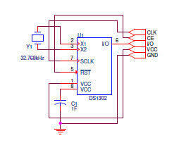
and proposed modification involves desoldering battery socket, modifying traces for supercapacitor (if needed) and solderting a capacitor - in this example 1F, 5.5V one

image

DS1302 has battery charging circuit builtin that is disabled by default and protected from accidental enabling. Full list of available charger configurations include (connected in series):

  • 1 Diode, 2kΩ
  • 1 Diode, 4kΩ
  • 1 Diode, 8kΩ
  • 2 Diodes, 2kΩ
  • 2 Diodes, 4kΩ
  • 2 Diodes, 8kΩ

When using DS1302RTC library it can be turned on using following command sequence, which configures it as one diode connected with 2kΩ resistor circuit:

RTC.writeEN(1);
RTC.writeRTC(DS1302_TRICKLE, 0xa5);
RTC.writeEN(0);

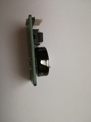
Installed supercap is about twenty years old Panasonic EECRF0H105 EDLC (or - to be more precise - series connected supercapacitor pair), salvaged from some old server motherboard, that was planned to be used as test case of long-time parameter retention (pair is chosen during manufacturing process to have similar parameters to not exceed maximum voltage of weaker capacitor - so it would be interesting to check if it is still true after many years of work), but it seems that the construction is more sturdy than expected (not only shrink-wrap but also a metal case) so access to individual cells would be rather difficult:

supercap construction

As a supercap can be thought of as series of capacitors with different series resistance, process of charging and discharging can be long - for example, in the circuit above, after initial charging and disconnecting (leaving only running RTC chip), 1V (from 3.97V to 2.97V) decreased after 16h (equivalent of 17uA discharge current).

Then, during 7h of charging, voltage increased to 4V and after next 72h to 4.27V (about maximum given than charging circuit includes series connected diode).

Next discharge period lasted 12h and decreased voltage to 3.82V (equivalent discharge current of 10uA).

After another 4 days of charging, equivalent discharge current dropped to several uA - which indicates how long it will take to fully charge such a capacitor.

Supercap powered model car

As for every component, supercapacitor needs proper design to give good results. In this point I would like to show some not-so-good design decision, resulting in suboptimal supercapacitor performance. Some time ago I have bought a DIY kit  that looked like this:

kit manual

Using this kit, one could build solar-powered toy car, designed to promote sustainable lifestyle (where car is charged when connected to a charging station shaped like a home with PV panel roof). Unfortunately, real life performance is bad - after sitting in full sun for several minutes, wheels start to turn slowly, giving a car very limited range when released.

Inside a car there is a small DC motor and a 3.3F supercapacitor:

image

image

And charging station contains a small PV panel:

image

It turns out that the problem is with charging process performance - when charged using constant current of 200mA (with voltage limit of 2.2V), wheels start to turn very quickly after a short time and after a minute or two charging current drops to about 40mA and stays this way - it seems that this is current consumption of the running motor. After 2 minutes of charging, motor runs for about 5 minutes - much better than when charged using provided PV panel.

Trying to estimate how much power we can get from installed PV module (with no datasheet available) we can do some simple math:

Assuming peak Sun irradiation at 1000W/m2 and panel's area of 0.000828m2, we will get at most 0.828W of input power. As our panel looks like a budget one, we can assume that it has efficiency in the range of 10%, resulting in current  in the range of 40mA at 2.1V - comparable with motor power consumption, so the charging process is very slow, giving the toy bad performance (at least in places with moderate Sun irradiation levels) - some motor disconnector during charging would be really helpful (or - better yet - bigger panel).

  • Sign in to reply
  • JWx
    JWx over 1 year ago in reply to redcharly

    Thanks! In fact I was expecting easier way to measure voltage difference between compound capacitors of 5V module - now I will have to cut through the metal can. It also shows how cost reduction is implemented - now the capacitors are only shrink-wrapped instead of using shrink-wrap as decoration (and place to put markings)

    • Cancel
    • Vote Up 0 Vote Down
    • Sign in to reply
    • More
    • Cancel
  • redcharly
    redcharly over 1 year ago

    Interesting application!

    • Cancel
    • Vote Up 0 Vote Down
    • Sign in to reply
    • More
    • Cancel
element14 Community

element14 is the first online community specifically for engineers. Connect with your peers and get expert answers to your questions.

  • Members
  • Learn
  • Technologies
  • Challenges & Projects
  • Products
  • Store
  • About Us
  • Feedback & Support
  • FAQs
  • Terms of Use
  • Privacy Policy
  • Legal and Copyright Notices
  • Sitemap
  • Cookies

An Avnet Company © 2025 Premier Farnell Limited. All Rights Reserved.

Premier Farnell Ltd, registered in England and Wales (no 00876412), registered office: Farnell House, Forge Lane, Leeds LS12 2NE.

ICP 备案号 10220084.

Follow element14

  • X
  • Facebook
  • linkedin
  • YouTube