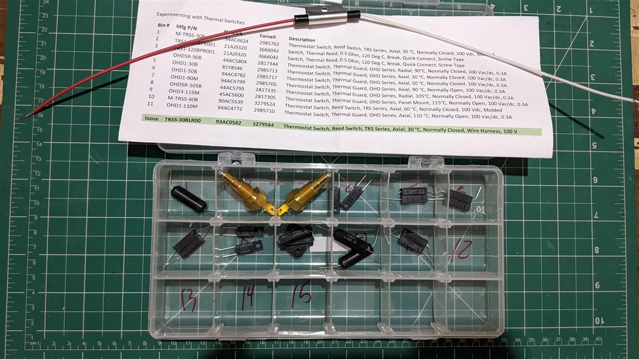
Firstly I would like to thank both KEMET and element14 for the opportunity. I have learned a lot of things in this experiment. I had received a kit with 12 sensors and all are amazing
for their respective applications.

In this experiment, I'm testing how one can check the accuracy and the point at which the conductivity begins and the effect of an external magnetic field on the device
Since I wanted to measure both temperatures near to the sensor and also the magnetic field, I thought of building one small experimental setup consisting of a microcontroller,
a display, a 3d magnetic field sensor and also a temperature sensor.
Here are the things that I chose:

1. 16x2 LCD display (Seeed Studio Grove LCD Display, I2C)
2. Arduino Uno MCU
3. Grove Button Module
4. Grove Buzzer Module
5. TLV-493D-A1B6 3D magnetic field sensor
6. Grove temperature sensor module
7. Jumper wires
8. Battery bank
9. Kemet thermal switches
10. Liquid Nitrogen Spray to simulate low temperature
11. Grove Arduino shield
12. Neodynium magnets
Connections and about the sensors:
KEMET thermal switches are temperature-dependent and also magnetic field dependent their make and brake can change based on the change in the
either of the two parameters. Hence I wanted to measure both the trigger points. So I will be using both temperature and magnetic field sensors to measure the
the temperature in * C and magnetic field in mT respectively.
Infineon TLV-493D-A1B6 is a 3D magnetic field sensor that can be used to detect minor changes in the magnetic field also and hence it is heavily used in automotive, robotics and
other industrial applications.
I will be using the sensor to detect the magnetic field around the sensor at the time of state change or make-break.
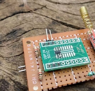
This magnetic field sensor is an I2C device and its address is 5E. I bought this separately and soldered it onto a small 18 pin SOIC holder PCB as its pitch is too small.

And connected 2 1k resistors as pull-up resistors for SCL and SDA lines.

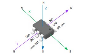
Sensor pinout.
The temperature sensor is an NTC type of thermistor with an OPAMP and some mathematical calculations to calculate the temperature.
Connections are as follows:
1. Buzzer >> Digital Pin 8
2. Button/KEMET sensor >> Digital Pin 7
3. LCD Display >> I2C (SCL-A5, SDA-A4)
4. Temperature sensor >> A0 of the ADC
5. Power Supply via Power Bank
The reason for using the switch button across the KEMET switches is to test the circuitry by pressing the pushbutton and also it includes the
debounce avoidance and pull-down circuit.

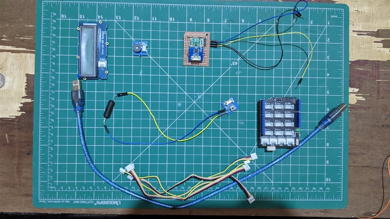
Wired setup
Let's Learn about the demo in the next blog
