The Story
This is the story of the Cozy Cat House, also known as The Green Barn.
The idea for this project began a few years ago when one of the cats we "inherited" decided she wanted to hang around outside, even on very cold days. We didn't want her roaming around killing birds, so she stays on a long leash. I figured she would stay out longer if she had a warm hutch to hang out in.
There are lots of cat cages on the market, but none seemed like meet all the criteria, which were:
it needs to be insulated
it needs a temperature controlled heater
it needs to keep snow and rain out
it needs to raised off the ground
it needs to be easy to clean
It needs to have some interlocks to prevent exposing a cat to dangerous conditions in the event of a failure
it needs to be small enough to easily bring inside whenever the cat is inside - since there are a lot of skunks, racoons, rabbits, squirrels and even stray cats in our neighborhood that would also like a cozy cabin to nest in.
Building something like this is outside my wheelhouse so it took a long time to figure out how I could do it with the tools I have. Even though the focus of an element14 project is electronics, I had to spend a lot of time building a functional house.
The electronics are overkill for this application, but I want to be able to monitor what is going on in the Cat House, figure out what features are useful and how to optimize the system.
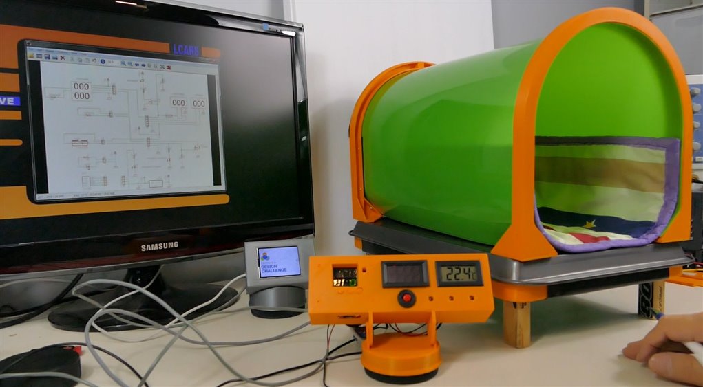
The Barn Build
The barn will be built with a dead air insulation layer between its double walls. The floor is a cookie sheet and the walls are cut from polyethelyne snow sliders. The bottom polyethelyne layer is held in place by a frame made from plastic toy hockey sticks. The carrying handle is mage from a real hockey stick, as are the legs. All materials are positioned and held by 3D printed brackets. The Cat House system required eleven 3-D printed parts.
The control system included:
- a dual display thermostat
- a digital voltmeter
- a digital ammeter
- a digital thermometer
- an active optical sensor
- a power supply
- an occupation indicator circuit
- a circuit breaker with breaker indication circuit
- a thermal switch and heater shutdown circuit
- an over temperature indicator circuit
- a whole spaghetti factory of wiring harnesses
Here is a video attempt to document the build, compressed from 16 video sessions.
Here are some circuits used in the control system:
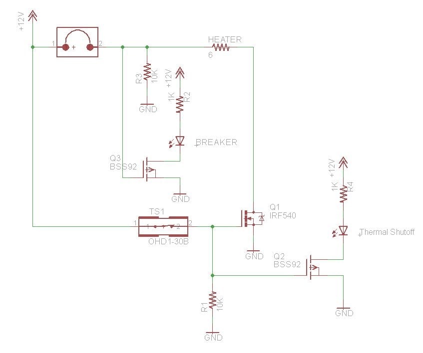
Overcurrent Circuit Breaker and indicator
I actually had to modify this in practice because the ammeter I used required its current shunt to be in the ground connection, but basically the LED is wired to turn on when the circuit breaker opens its switch.
Occupation Sensor
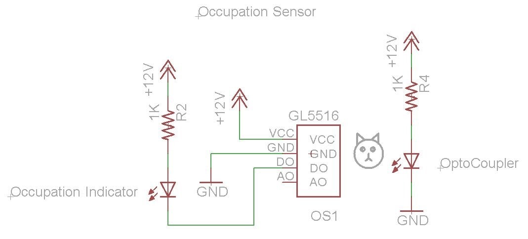
The occupation sensor detects the presence of a cat in the house using a photodiode with an adjustable comparator to allow optimal tuning for the application's ambient light conditions. Basically an LED supplies the light and when a cat blocks the LED light, the photodiode detects the change in incident light. This drives an indicator LED on the control panel.
Thermal Shutoff
The thermal shutoff works by controlling the gate voltage of a big power N-channel FET (Q1), when it gets too hot the thermal switch opens and the FET turns off, preventing current from flowing through the heater. The P-channel FET just turns on the indicator LED when the thermal switch opens.
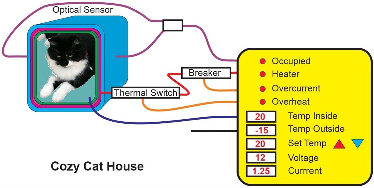
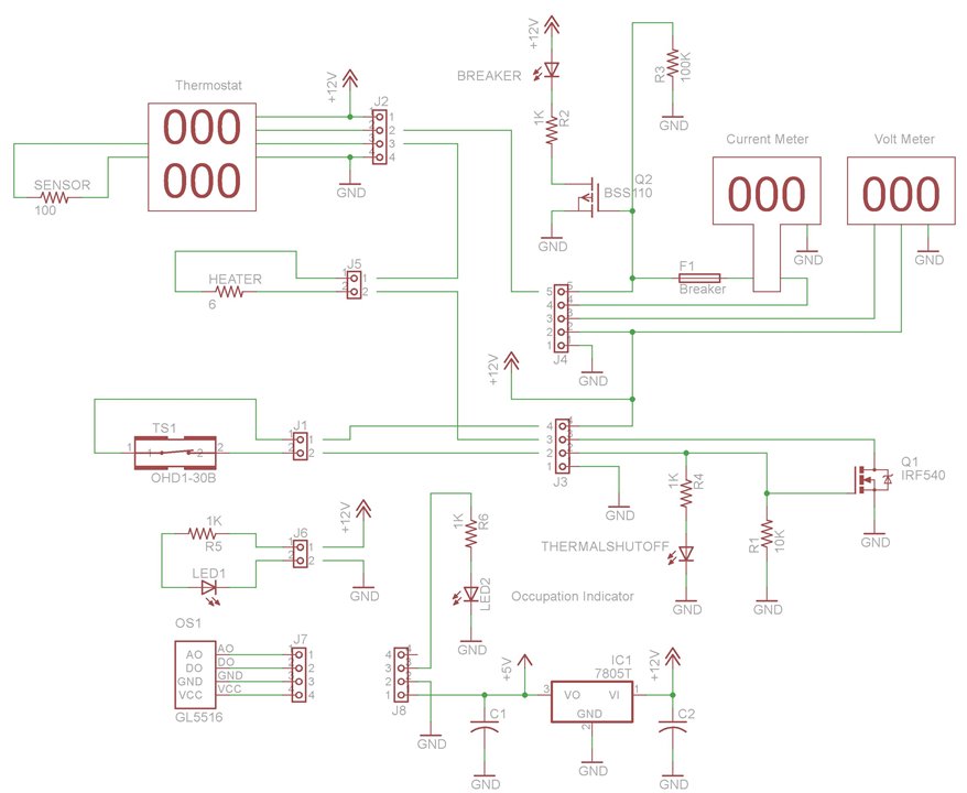
Overall Cat House Wiring Diagram
I had to create this diagram and have it in front of me while wiring up all the different subsystems. I made a few minor changes about where connections were made, but without this diagram, I would have been totally confused about what is connected to what.
This project is also intended to highlight Kemet thermal switches, one of which is used to provide thermal shutdown of the heater in case the temperature gets too high in the lair. The 30 degree switch used in this applications was easily and reliably able to shut down the heater long before temperatures reached dangerous levels. It should be noted that the electronics and control systems used in this project could all be replaced by a simple thermal switch configured as a thermostat. Such a system is demonstrated later in this blog.
Another application I really wanted to tackle was a system to improve my 3D printer filament performance.
Filament Performance Problem Description
This section of the blog addresses my pressing need to prevent the PLA in my 3D printer from breaking. PLA wound on a spool while still warm tends to stay in that curled shape after it has cooled off. When feeding it into a printer, the filament must be straitened out of the curled shape which induces stress in the filament. If the stress is maintained for a day or two, while sitting idle between print jobs for example, it will eventually break the filament.
Solution Overview
To tackle this problem, I will try to anneal the filament as it comes off the spool, which hopefully will lower the stress of it taking on a new shape and allow the filament to stay in the printer between prints. To do this I need a temperature controlled heater. The simplest solution would be to use one of the Kemet thermal switches to act as a thermostat, however I need to experiment with different temperatures to see what works best, so I will use an adjustable thermostat. Once I determine what the best temperature is, I can use the Kemet thermal switch in my other printer. While I am experimenting with different temperatures, I will use a Kemet thermal switch as an over-temperature safety shut-off switch, so both systems will use a thermal switch.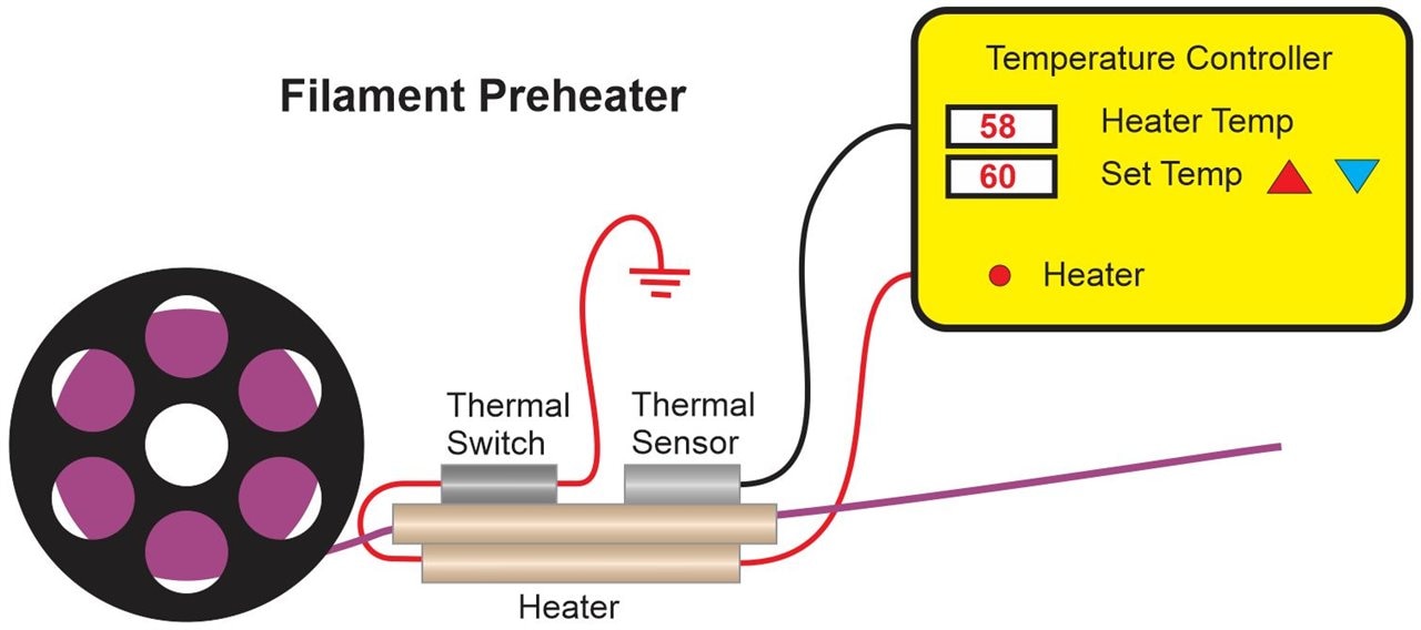
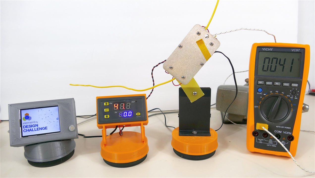
Heater Subsystem
I had to think for a while about what features would achieve PLA annealing in the geometry and time frame of a print job. The PLA in my 3mm filament printer actually moves very slowly and I didn't want it hanging around a hot annealer for long periods of time. I want to keep the temperature well below melting temperature (150C) but above the glass transition temperature (65C). The filament needs enough time to heat up past the glass transition temperature, but it is moving as the printer lays it down, so the annealing zone needs to be a long enough to keep it in the heater long enough to heat up.
I am hoping 10 cm is enough.
I flashed on a recollection that I had salvaged some copper tubing a long time ago, which should be suitable for transferring heat to the filament. I don't remember what the tubing came out of, I just remember thinking sooner or later this tubing will be useful. I love it when I just happen to have something unusual that I suddenly need.
The next issue is how to heat the tube. I thought of soldering irons and 3D printer filament heaters, but I want to save my spare heaters for their intended applications. Then I noticed that some power resistors I had purchased in bulk were just the right diameter to fit in the copper tube and I figure they can take 100C temperatures. So now I needed another section of tubing to house the "heater" resistors. I tried three resistors out in a 3 inch tube and the adjacent filament tube reached 84 degrees with 12 V applied. That might work but I want a little more heat to be safe, so I made a second heater tube. Now the tubes needed to be thermally connected, so I simply soldered the three of them together. Actually it wasn't all that simple, I tried a heat gun, but couldn't get the right heat at the right location without blowing solder all over the place. Even the flux was curling up and blowing away. I wanted to stay away from firing up a torch like plumbers use (mostly because I don't have a propane tank) Eventually, I tried my trusty Hakko soldering iron, and it had no problems, even with the massive heatsink of 3 copper tubes. To hold the tubes during soldering, I placed them in cutouts in some jury-rigged "scrap" FR4. It isn't really scrap since I keep this stuff and use it for a lot of structural purposes. In fact I am using some to make the heater holder. Now with 2 heater tubes the filament tube reaches well over 100 degrees.
To mount the heater assembly in something that can withstand heat and prevent contact with the hot heater I am making use of some "scrap" FR4 and an aluminum bracket. The bracket will allow the heater to rotate to an optimal angle.
Thermostat
The digital thermostat runs off 12 V and displays both the set point temperature and the actual temperature. I 3D printed a housing and stand for the thermostat. Since I had to use 2 different thermostats, I ended up designing and printing 2 housing.
Thermal Shut-off Switch
The Kemet thermal shut-off switch is mounted on the filament tube. It drive a FET that controls the power to the heater. It need the FET because the thermal switch cannot handle the full current of the heater.
The Build
The build included several more 3-D printed parts for the 3 chassis' involved plus some aluminum and copper fabrication plus some fiberglass to manage the heat without getting the 3-D printed parts too hot.
Video Demo of the Annealing System
Thermal Performance
The warm up times are as follows:
60 C ->120 sec
80 C -> 200 sec
100 C -> 300 sec
The feed rate of the printer is approximately 3 mm / sec, so the the filament is in the heater tube for 60 seconds.
The temperature of the filament at the exit is 95 C.
Annealing Performance (Version 1 System)
A brittle curled sample was annealed by feeding as the printer would do it, then reformed with a little curve and left to cool for 24 hours.
Then it was bent to see what radius would break it.
After annealing and stretching, the cooled shape had significantly less curl, and so far does not look like it is in danger of breaking.
It was a little extreme to take the curl right out, that is probably a higher temperature than desired, since the filament diameter can get distorted.
The heated tube was too constricting on the curly filament which caused excessive friction.
PLA Annealer Discussion and Conclusions
Annealing with a hot tube like this works but not the way I thought it would.
The filament gets softer at a lower temperature than I expected. This means the temperature and hot duration need to be fairly tightly controlled to prevent distorting the filament diameter.
The friction in the tube is quite a bit higher than I expected. This means it is not ideal to be pulling the filament through the tube, since it could stretch and get thinner if it gets a bit too soft.
A better method would be to have the filament pushed into the tube, but this requires a motorized feeder that has a control system to keep precise pace with the printer feed.
I learned that annealing will solve my problem, but a really good annealing system might require a much bigger project and a much more complex control system.
However, after thinking about it some more, I decided to try a different heater geometry. This one is a rectangular "tube" that allows the filament to bend significantly in one direction so the friction is much lower. The heater tube is no longer intended to straighten the filament, it is just annealing it and the normal filament guide will do all the straightening.
I also decided to repair the thermostat that had a defective relay. I did not have a suitable relay, so I reworked it to use a big P-channel FET instead of a relay. While I was at it I added some internal wiring and a power jack to make external wiring much simpler. I even inserted some fiberglass guides to prevent the filament from directly touching the heaters.
This system took a bigger effort to build than I expected and involved scrounging much different materials than normal and improvising new methods to work with them, but it was a useful learning experience. The second version of the filament annealer works much better than the first one, but it will need to run through a few different spools of filament before I know if it is solving the problem for all scenarios. The latest build maintains the temperature in the cavity plus or minus one degree C. This is great but it takes quite a while to change temperatures, so it may not be able to keep up if it is necessary to change the temperature based on filament feed rate changes.
If it turns out that one fixed temperature solves the filament breakage issue, than it would be feasible to replace the whole thermostat with a simple Kemet thermal switch driving a power FET.
I am glad I spent the extra time to revise the design and rework the thermostat, even though it ate into time needed for testing and documenting all the revisions and dead ends. I now have a much better annealer and there is no relay to wear out.
Thermal Switches & a Thermal Switch Based Thermostat Design
I like to build systems to experiment with the technology provided in the kit, but the two systems above did not cover all the components in the kit, so I embarked on another journey to build test apparatus that could test all the thermal switches.
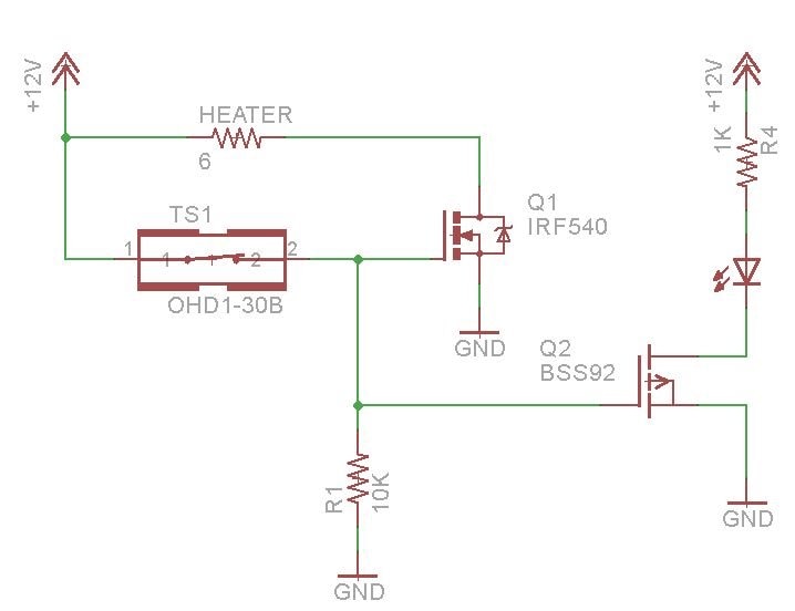
One circuit is a simple thermostat that turns any switch into a thermostat controlling a heater. This allows both the activation and deactivation temperatures to be monitored while demonstrating a simple and useful circuit. The circuit maintains a constant temperature and has an LED to indicate when the heater is on. The schematic for the simple thermostat is shown below:
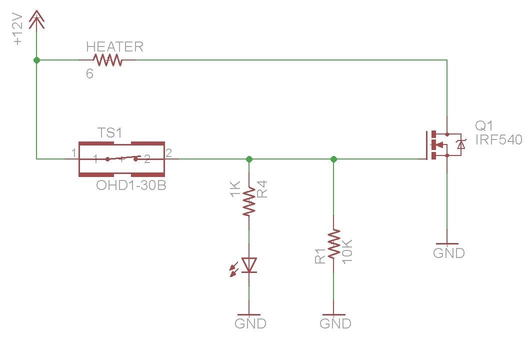
For tightest temperature control the thermal switch should be placed close to the heat source with good thermal conductivity between the heat source and the thermal switch.
Magnetic Field Detector
Another even simpler application is a magnetic field detector. That circuit is shown below:
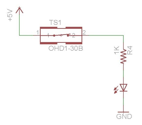
I created a video to demonstrate these circuits in use with various thermal switches included in the kit:
Conclusions & Discussion
Experimenting projects are always fun because they have that added dimension of exploring the unknown. My experimenting projects always aim at building real applications to see how the technology works in interesting implementations. Sometimes that is the only way to understand the potential pitfalls. Things like how to get the temperature of a device like this to be at the same temperature as the thing you are trying to control, or how complex geometries affect heat transfer and thermal time constants. I struggled mightily with this project because the heavy building aspects of my experiments, and the need to persist until they worked properly, limited the amount of testing I had time for, and there were quite a few unexpected adversities to overcome. Nevertheless, I got a good appreciation of Kemet Tokin thermal switches, which I find have impressive performance. It is unusual to find this much functionality in a simple and relatively small two-terminal device. There is some secret sauce in how they precisely control the Curie temperature of the Tokin Thermorite material to make devices with different temperature thresholds, and using this property to control a read switch is very clever. The fact that no external circuitry is needed for operation makes these devices very reliable and they achieve excellent accuracy. Also they do not require any power to operate other than the temperature they are sensing, this is such a neat feature. Normally open and normally closed options add to the flexible uses for these devices.
It would be extremely boring to include all 34 videos I shot of thermal switches in action, but hopefully I have included enough material here to keep it interesting and raise awareness that these thermal switches work well, are easy to use, and can simplify the tasks of thermal control and thermal monitoring.
I would like to thank Kemet and element 14 for sponsoring this experimentation challenge. It was interesting, I learned a lot, and even my cats had fun with it, plus I have a whole cache of high performance thermal switches to use in future projects.
Relevant Links:
/challenges-projects/design-challenges/experimenting-with-thermal-switches/
https://ec.kemet.com/blog/wp-which-thermal-sensor-to-choose/
https://ec.kemet.com/blog/if-its-not-thermorite-then-its-thermo-wrong/

Top Comments
-

fmilburn
-
Cancel
-
Vote Up
+1
Vote Down
-
-
Sign in to reply
-
More
-
Cancel
Comment-

fmilburn
-
Cancel
-
Vote Up
+1
Vote Down
-
-
Sign in to reply
-
More
-
Cancel
Children