About Me
I am a junior year Electrical Engineering undergraduate student who usually falls behind electronics and from my early days, I am fascinated by electronic stuff and curious on what goes into making(breaking) them. I remember breaking down things to see what's in and realizing that I understood nothing with the complement of wrecking the stuff and losing it. If you ever have broken into something and couldn't fix it back, leave me a message and let's discuss. My areas of interest include Embedded Systems and Analog/Power Electronics. Apart, I work as an intern with a CleanTech startup for developing technological solutions to help restore the air around us.
The Kit
The kit came with all the mentioned sensors, 2 of them having wires and a metal pad attachment for accurately sensing temperature(I like it's design)
 '
'
The Plan
ThermoPID: Using thermal switches for regulating DC/DC converter IC's temperature by initiating active cooling with a proportional, integral, derivative(PID) controlled fan. So, what's the need? Probably manageable if I didn't have a lot of these thermal switches. But here it is:
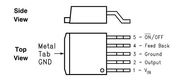
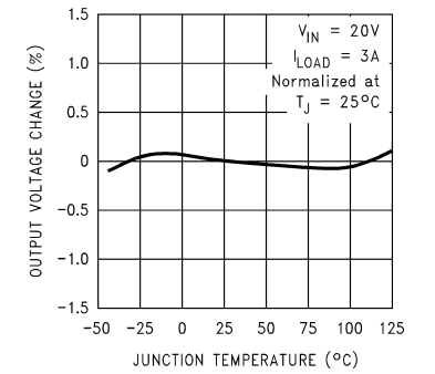
The application is for TI's LM2596ADJ simple switcher 3A max DC-DC converter(although it's suitable for discrete SMPS and other power converters which bleed a lot of heat). Of course, the chip is designed keeping all thermal considerations, but I am creating a scenario where the LM2596 overheats and is about to runaway thermally as an evaluation platform. This can happen when the device is over throttled and when thermal considerations like using the on-chip thermal metal pad for sinking heat are not wisely taken. For example there are many Junction Temperature vs X plots shown in the datasheet indicating what can happen over temperature variations. This is quite insignificant for +/- 15 *C variations from standard 25 *C but over large variations, they pull down the efficiency of the DC/DC convertersion system.


The 73% efficiency of this chip at full load isn't that great and worsening it should be prevented. So the plan is to have an intelligent, low-power, efficient external cooling system for the chip to always operate at maximum efficiency possible by tacking the excess temperature variation issue on loading.
Implementation
Hit 0: Design circuits wisely taking all thermal considerations, try to sink maximum heat by the given on-chip thermal pad itself or don't ever touch electronics :(
Hit 1: Sometimes the design may not be very accommodating or you may be simply working with the chip on perf board. So using a small cooling fan would do the job crudely.
Hit 2: Efficiency of the external cooling system matters as after all it's that extra energy needed for efficient power conversion. So overall power conversion efficiency includes efficiency of DC/DC converter and of the active cooling system.
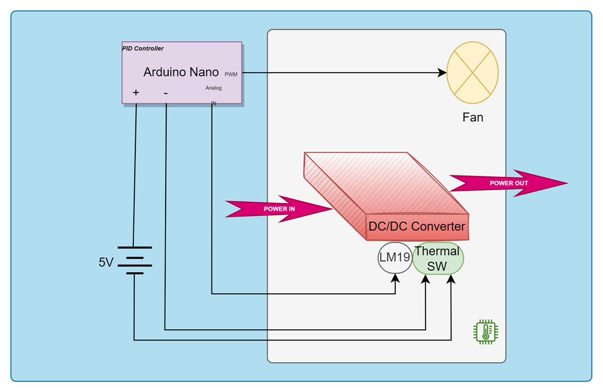
Hit 3: So a thermal switch is used to detect a point of ~60 *C and initiate active cooling with a fan. Simply running a fan with no exact measure of chip's junction temperature would go dumb. The junction temperature of a chip isn't purely linear with load and time. So to improvise the cooling system efficiency, LM19 temperature sensor actively monitors the live junction temperature(actually the metal tab temperature) and controls the fan speed using the PID algorithm.
So overall, the cooling system is switched ON by sensing Tj with a thermal switch and then active cooling is initiated until the Tj falls back to the thermal switche's threshold.
Block Diagram

Thanks to element14 community and KEMET for planning, sponsoring this and choosing my idea for this challenge. Excited to build up the design and test it out!
