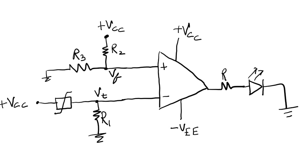
I proposed three experiments with thermistors in my first blog, this is the first one. Using a thermistor as a thermal switch for auto-cutoff/thermal protection of electrical appliances. This can help check for overheating of electrical appliances such as heaters, kettles, and irons and help prevent fires due to overheating.
The design of the auto-cutoff circuit is based on the simple principle of opamp comparator. First step is to design a comparator using an opamp and setting the reference voltage using a potentiometer. The potentiometer can also be used to set the sensitivity of the thermal switch. I will explain this later.
At ambient temperature, the thermistor will have a certain resistance which can be found experimentally by measuring with a DMM or just by looking at the datasheet.
Next, a voltage divider is created using the thermistor and a fixed value resistor (R1), since the thermistor resistance (Rt) is temperature dependent, the voltage at the junction of R1 and Rt will vary let's call this voltage Vr. This voltage is compared with the fixed reference voltage set using the potentiometer Vf.
The comparator can give different outputs depending upon how it is wired. A simple operation of comparator is
If V+ > V- output is Vcc and if V- > V+ output is -Vee
Here, V+ and V- are the voltages present at the non-inverting and inverting terminals respectively. An interesting thing to note here is that V+ is not equal to V- as we assume most of the times due to the virtual ground and virtual short. This is because the assumptions are only true when there is negative feedback in the opamp. Comparator is an open loop configuration with no feedback.
Coming back to the auto-cutoff circuit, now the two voltages can be fed to the opamp comparator, I want the device to cutoff, which means the output of the opamp should go to low as the temperature rises. Which means V- voltage should be greater than V+ so the voltage Vr is connected to the inverting terminal and Vf, the fixed voltage is connected to the V+ non-inverting terminal of the opamp.
Now when the temperature rises, the voltage at the thermistor-resistor junction rises and hence the opamp output drops to -Vee thereby turning off the device.

For proof of concept, I have used an LED as the output device and I'm using a soldering iron to control the temperature around the thermistor.
It can be seen from the video that as soon as I touch the soldering iron to the thermistor the LED goes off and as the thermistor cools off, the LED again turns on.
The delay or the sensitivity of the switch on/off of the LED can be controlled by changing the fixed reference voltage set using the potentiometer. Greater the difference between V+ and V- less sensitive the comparator circuit is.
In my next blog, I will be describing an interesting project I'm working on using thermistors. I hit some logistical issues during my experiments and the due date of the contest is already over, so my next blog may not be considered but nevertheless, I will still work on the project as the main idea behind this is experimenting!
