Peltier or Resistor?
To change the temperature of the chamber I evaluated 2 alternatives: a Peltier module and resistor. Peltier modules are more versatile as they are heat pumps that can either heat or cool depending on the current direction. On the other side, resistors can only heat, but to their advantage the are easier to install. A Peltier module needs to be installed at the interface between the temperature chamber and the external environment. Moreover, unless it is used at very low power, a heatsink and a fan need to be used to quickly exchange the heat between the environment and the Peltier. It is also much easier/cheaper to inject a lot of heat with a resistor than with a Peltier.
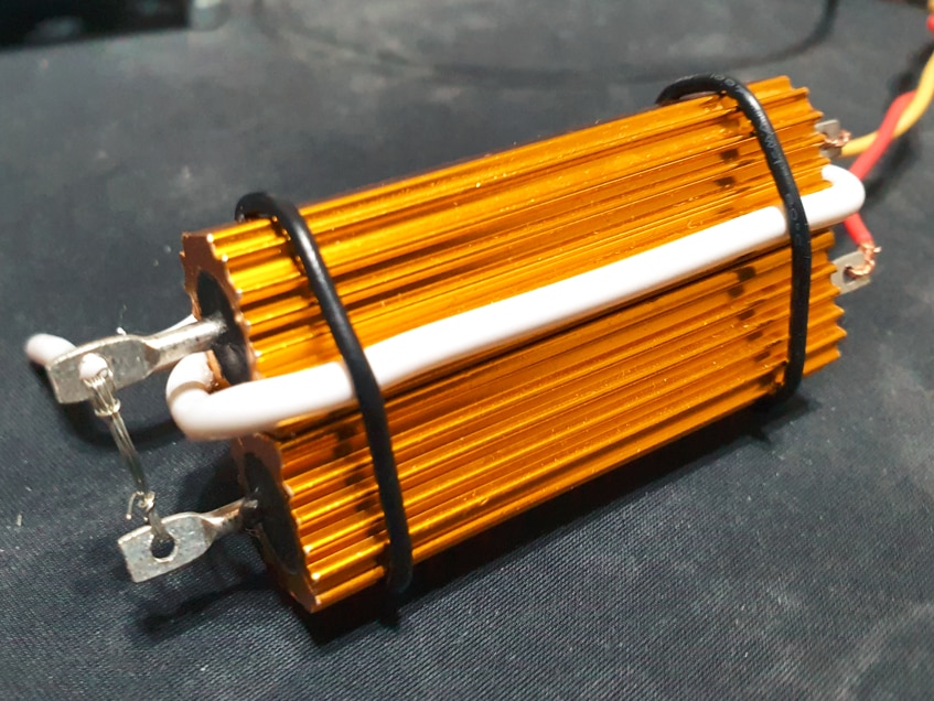
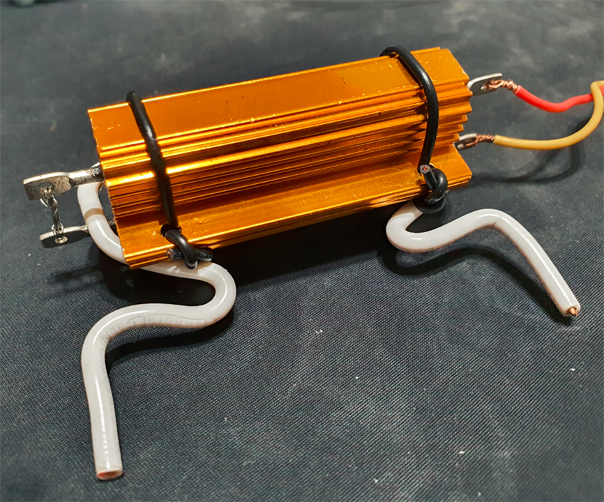
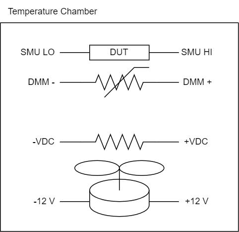
Considering the simplicity of using resistors, and also that for most of the times electronic components are exposed to higher temperatures, I decided to use resistors: Two 8 Ohm, 100 W resistors.
Fan
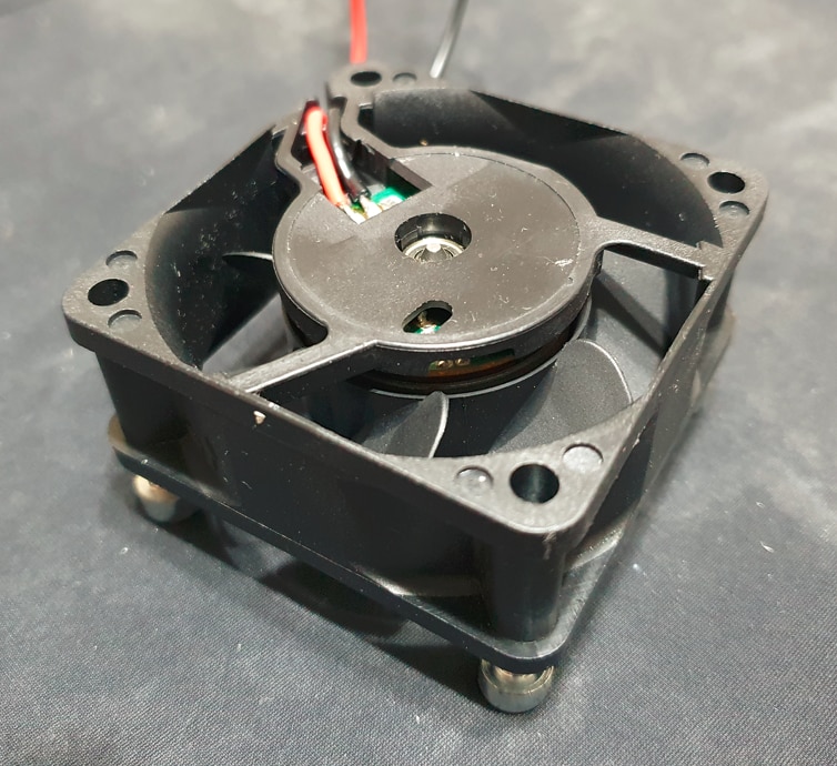
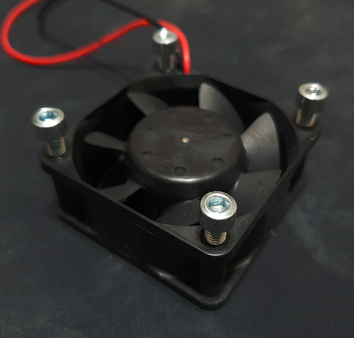
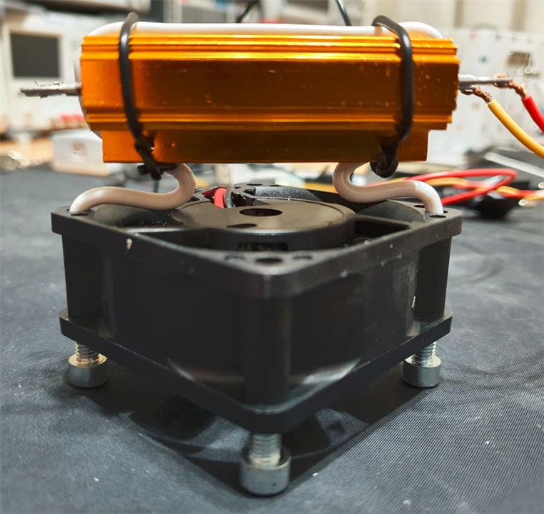
To keep the chamber air temperature relatively uniform and avoid high temperature air to accumulate at the top of the chamber I used a fan. I have lots of fans salvaged mostly from computers, but I could not find the operating temperature of any of them, so I ended up using one that was relatively small and "high power" (~6 W). To leave space between the "sucking" side of the fan and the chamber wall, I screwed 4 screws to the fan.
A copper cable was used to fix the resistors close to the fan blowing side.
The Chamber
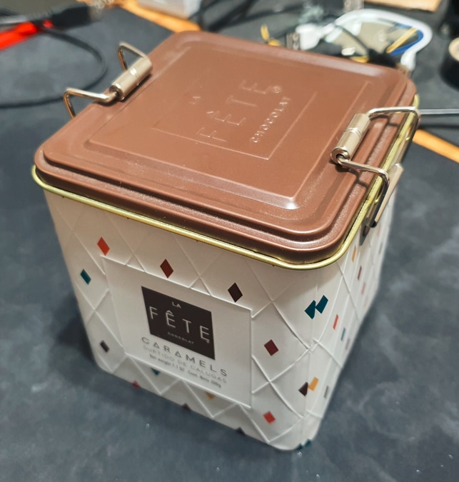
Ideally the chamber should be able to withstand the testing temperatures and at the same time provide good thermal insulation. Continuing with my policy of just using what I had in hand I ended up using a ~10 cm caramel cubic metal box.
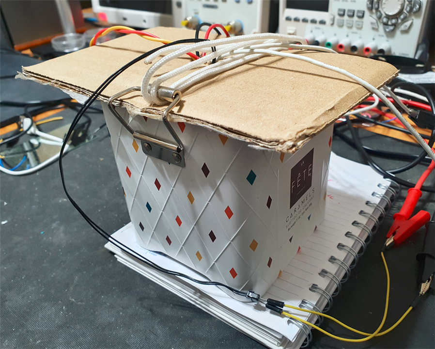
To keep things simple, instead of drilling a hole into the cover to then close seal it to avoid hot air to leak out of the box, I just used a cardboard (which also has the advantage of having lower thermal conductivity). The complete system looked like this:
Testing a Diode
To test the system I I-V traced a diode at different temperatures.
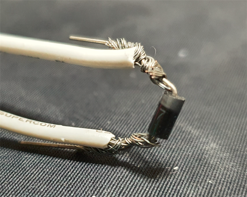
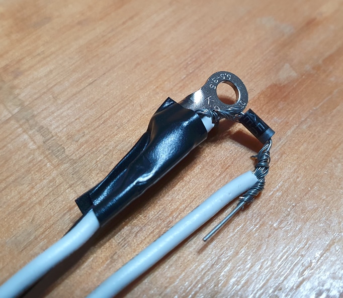
I had such a clutter on my bench that I avoided using solder, it looks ugly, but the connection is still solid. To measure the temperature close to the diode I just taped them (again, ugly but functional).
I probed the diode at steps of 5 °C, from 30 °C to 60 °C and got the following results:
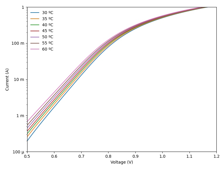
The relative uniformity of the separation of the curves suggests that the diode was measured at equally spaced temperatures, so we could call the experiment a success.
Conclusions
To test temperature sensitivity of components have previously used mineral oil as heat-transfer fluid, so I took this design challenge as an opportunity to use air instead as a heat-transfer fluid. The plan was not to build a functional system but just to build a proof of concept to acquire experience so that in the future I could build a functional system. Compared to the oil-based system which was made of an oil-filled beaker, and a magnetic stirrer, there were some important differences. The oil has much higher heat capacity than air so it makes heat transfer much easier. Specifically, it can absorb heat at a much higher rate, and in this way change temperature at a faster rate. Also, stirring oil with the magnetic stirrer injects energy at a much lower rate than with a fan (6W). And finally, the oil chamber can be made much smaller and is also simpler to build than a relatively hermetic air chamber. But the main advantage of using air is that it is cleaner to work with than the messy oil, which is easy to spill and difficult to wash out.
Lessons learned
Most of the experimental results were more or less expected except one. I used 6W small fan to generate enough air flow so that the whole chamber would stay at a uniform temperature. This did not happen, and as a matter of fact there was a very noticeable temperature difference between the chamber surface directly above the fan and the surface that was getting the air stream indirectly. This was probably the result of multiple factors, but probably the dominating one was the low air thermal capacity and the chamber wall high thermal conductivity which facilitated heat to flow out of the chamber. Other factor that may have played a relevant factor is that the air flow may have generated regions with poor access to the heated air.
An effect that was much worse than what I expected was the "inertia" of the system. The metal encased resistors with its high thermal capacity could keep heating the chamber for around a minute if I gave them a short power pulse followed by a complete power cutoff. This of course adds difficulty to the control algorithm. My initial plan was to heat with a small grid of nichrome wire to avoid this, but I ended up using high power resistors for safety reasons, as the chamber was opaque and I would not be able to see if something burned inside.
One big drawback of the design is that the 6W fan injected too much heat power that it made the chamber converge to roughly 10 °C over the ambient temperature (which is the reason that I began testing the diode at 30 °C)
Ideally I would have liked to test temperatures at ranged up to ~150 °C to cover most of the operating temperature of electronic components, but fans that can operate at such high temperature are expensive and not very common.
A functional and inexpensive temperature chamber for 0 - 100 ºC (at 20 ºC ambient)
Building a system that can be used to evaluate components at temperatures in the range of 0 ºC to 100 ºC does not look that difficult. This is what I would try first:
Fan
Digikey shows only 4 fans that can operate at 100 ºC. I would try the inexpensive ($11.6) EFB0512VHBBBN which is relatively silent (35.0dBA) consumes only 1.76 W and has an air flow of 13.1 CFM.
Heating/Cooling
To be able to test temperatures below the ambient temperature I would use a Peltier, moreover, a Peltier would allow me to compensate for the heat generated by the fan and the DUT, which is key to evaluate the DUT at temperatures just a few degrees over the ambient temperature
Temperature sensor
Thermistors are relatively inexpensive, but to keep things simple accurate I would use TI's TMP117 which has an accuracy of +-0.1 ºC.
Chamber
To keep things simple, I would 3D print the chamber as there are multiple 3D printing materials with glass transitions above 100 ºC (i.e: The inexpensive ABS has a glass transition of 105 ºC). I would design the chamber as a loop so as to avoid regions not easily reached by the heated/cooled air. 3D printing materials have lower temperature conductivity than metal (such as the chamber that I used in this project), but it still require some proper design to reduce the heat leakage to the minimum. To reduce the leakage I would focus on 3 objectives: makes walls thick, use low thermal conductivity lattices and keep the external wall surface low. Ideally the chamber should be hermetic, It would use O-rings for this, and it would connect the DUT to the outside through an airtight PCB with multiple connectors at each side. To make it possible to see what going on inside the chamber, glass or polycarbonate (glass transition of 145 ºC) could be used to build a small window. To avoid leakage through the window It would have to be built with multiple layers with air between layers.

-

DAB
-
Cancel
-
Vote Up
0
Vote Down
-
-
Sign in to reply
-
More
-
Cancel
Comment-

DAB
-
Cancel
-
Vote Up
0
Vote Down
-
-
Sign in to reply
-
More
-
Cancel
Children