element14 Community
element14 Community
    Register Log In
  • Site
  • Search
  • Log In Register
  • About Us
  • Community Hub
    Community Hub
    • What's New on element14
    • Feedback and Support
    • Benefits of Membership
    • Personal Blogs
    • Members Area
    • Achievement Levels
  • Learn
    Learn
    • Ask an Expert
    • eBooks
    • element14 presents
    • Learning Center
    • Tech Spotlight
    • STEM Academy
    • Webinars, Training and Events
    • Learning Groups
  • Technologies
    Technologies
    • 3D Printing
    • FPGA
    • Industrial Automation
    • Internet of Things
    • Power & Energy
    • Sensors
    • Technology Groups
  • Challenges & Projects
    Challenges & Projects
    • Design Challenges
    • element14 presents Projects
    • Project14
    • Arduino Projects
    • Raspberry Pi Projects
    • Project Groups
  • Products
    Products
    • Arduino
    • Avnet Boards Community
    • Dev Tools
    • Manufacturers
    • Multicomp Pro
    • Product Groups
    • Raspberry Pi
    • RoadTests & Reviews
  • Store
    Store
    • Visit Your Store
    • Choose another store...
      • Europe
      •  Austria (German)
      •  Belgium (Dutch, French)
      •  Bulgaria (Bulgarian)
      •  Czech Republic (Czech)
      •  Denmark (Danish)
      •  Estonia (Estonian)
      •  Finland (Finnish)
      •  France (French)
      •  Germany (German)
      •  Hungary (Hungarian)
      •  Ireland
      •  Israel
      •  Italy (Italian)
      •  Latvia (Latvian)
      •  
      •  Lithuania (Lithuanian)
      •  Netherlands (Dutch)
      •  Norway (Norwegian)
      •  Poland (Polish)
      •  Portugal (Portuguese)
      •  Romania (Romanian)
      •  Russia (Russian)
      •  Slovakia (Slovak)
      •  Slovenia (Slovenian)
      •  Spain (Spanish)
      •  Sweden (Swedish)
      •  Switzerland(German, French)
      •  Turkey (Turkish)
      •  United Kingdom
      • Asia Pacific
      •  Australia
      •  China
      •  Hong Kong
      •  India
      •  Korea (Korean)
      •  Malaysia
      •  New Zealand
      •  Philippines
      •  Singapore
      •  Taiwan
      •  Thailand (Thai)
      • Americas
      •  Brazil (Portuguese)
      •  Canada
      •  Mexico (Spanish)
      •  United States
      Can't find the country/region you're looking for? Visit our export site or find a local distributor.
  • Translate
  • Profile
  • Settings
Experimenting with Thermistors
  • Challenges & Projects
  • Design Challenges
  • Experimenting with Thermistors
  • More
  • Cancel
Experimenting with Thermistors
Challenge Blog Blog #3: Thermistors Minitutorial Part 2 - Measuring Temperature Using Thermistor and Arduino
  • Blog
  • Forum
  • Documents
  • Files
  • Mentions
  • Sub-Groups
  • Tags
  • More
  • Cancel
  • New
  • Share
  • More
  • Cancel
Group Actions
  • Group RSS
  • More
  • Cancel
Engagement
  • Author Author: misaz
  • Date Created: 29 Jul 2022 6:30 PM Date Created
  • Views 28241 views
  • Likes 11 likes
  • Comments 4 comments
  • resistance
  • voltage divider
  • thermistor
  • adc
  • arduino
  • experimenting with thermistors
  • thermistors
Related
Recommended

Blog #3: Thermistors Minitutorial Part 2 - Measuring Temperature Using Thermistor and Arduino

misaz
misaz
29 Jul 2022
Blog #3: Thermistors Minitutorial Part 2 - Measuring Temperature Using Thermistor and Arduino

I welcome you to my next blog post as part of Experimenting with Thermistors Design Challenge. In previous 1st blog post I described my plans as part of this competition and in second blog post I started my series of 3 mini tutorials showing usage of thermistors with Arduino. In this blog post I will continue and today I will automate measurement process which I recently did manually using multimeter. In this blog post I will measure resistance of thermistor using Arduino and evaluate measured resistance using table of corresponding temperatures from Molex Thermistor Datasheet.

Connection

The first step is measuring resistance of thermistor. The easiest way is using voltage divider and analog pin. Voltage divider works in way that voltage on wire between two resistors depends on ratio of resistor values. In our voltage divider one of the resistors is thermistor with variable resistance and second resistor is static resistor with known value. Resistor with static known value should be accurate as much as possible, but in case of inaccurate resistor you can manually adjust value in code later. One end of the voltage divider connects to 5V of Arduino and second to the GND. Middle terminal of voltage divider will face variable voltage depending on ratio of thermistor actual value and known resistor value. This voltage is sensible by ADC of Arduino, so connect it to the A0 or other analog pin of Arduino. Value of resistor depends on thermistor value and required range of operation. For Molex thermistor 215272-3707 which I use in this project I chosen 2k2 but many other values will also work well. Schematically connection looks as follows:

image

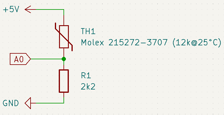
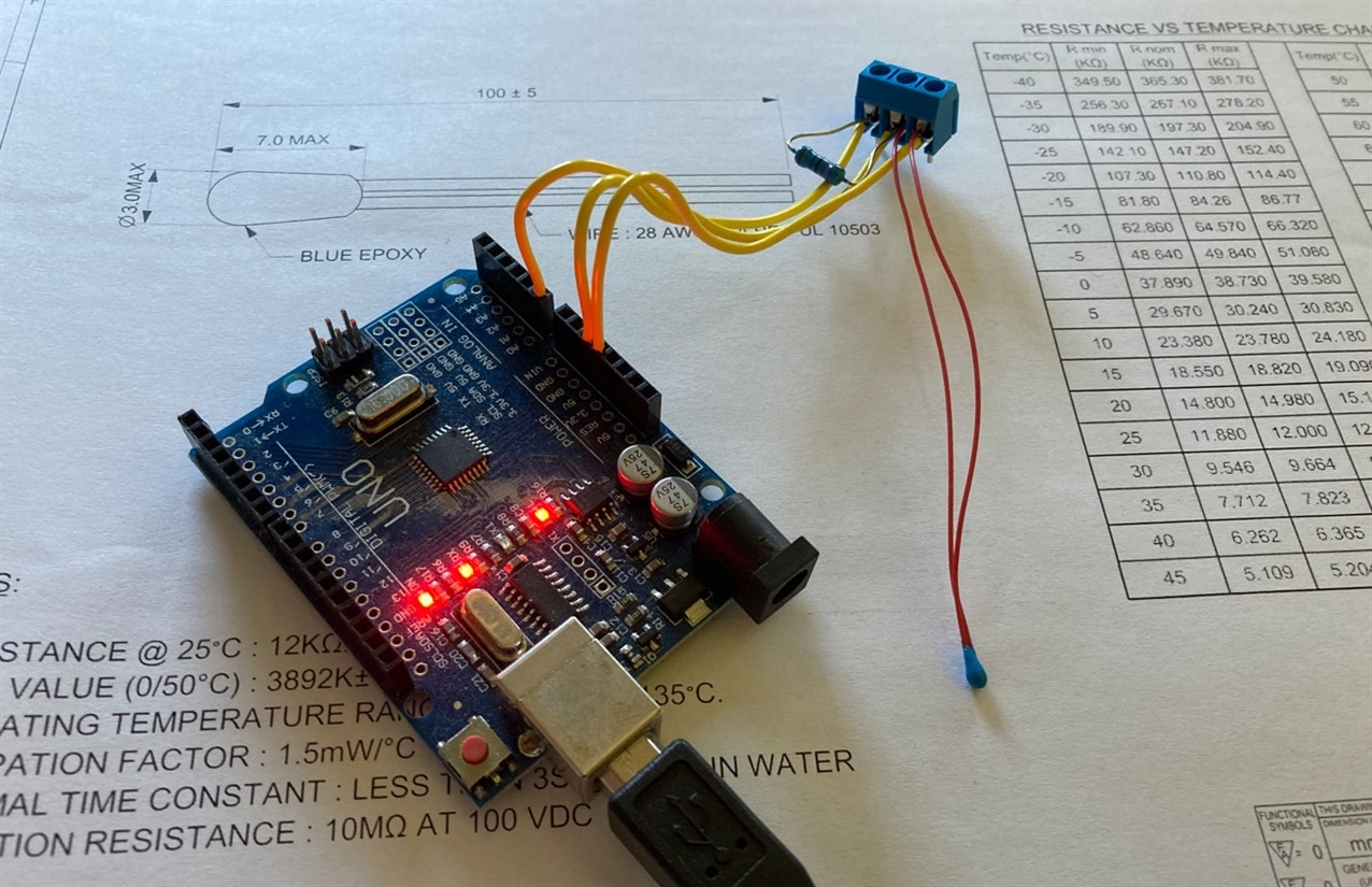
In real world I interconnected components using terminal block. I did not use breadboard this time. It is good to reduce resistance of wires and joins as much as possible because they affect accuracy of measurements. Connection look as follows:

image

Converting voltage to resistance

The next step is finding formula which we use for converting measured voltage to resistance. Generic formula for computing voltage drop of resistor as part of voltage divider is following:

image

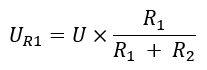
In our case R2 is thermistor:

image

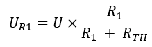
Now we need to express Rth from formula. R1 is constant (2k2) and U is constant (5V on Arduino).

image  

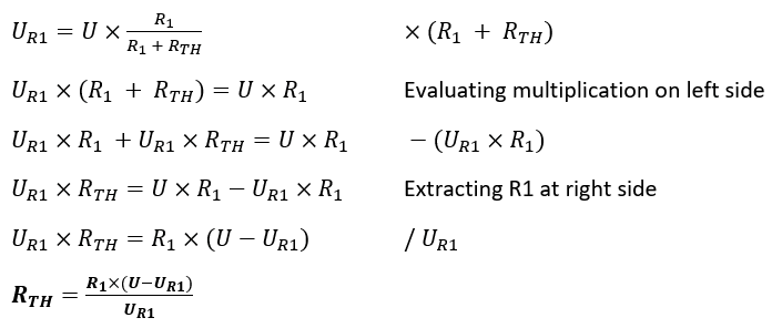
After placing known constants (R1=2k2, U=5V):

image

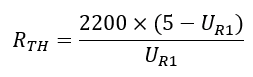
And we have simple formula expecting voltage equivalent to voltage on A0 pin and outputting resistance of thermistor which we can use for measuring temperature.

Arduino Code

Now we can use all knowledge from previous paragraphs to write Arduino code.

In setup function you only need to initialize Serial port:

Serial.begin(9600);

Before we start coding our application logic, let’s declare constants used in circuit. VCC is voltage used for powering Arduino and R1 is value of static resistor in voltage divider:

float R1 = 2200.0;
float VCC = 5.0;

In loop function we will read analog pin. This we can do using analogRead(A0) call. This function provide value in range from 0 to 1023 corresponding to measured voltage. We will divide it by 1023.0 (float) which will convert measured value to decimal number in range between 0 and 1. After this we will scale this value to real voltage range by multiplication value with ADC reference which is the same voltage used for powering Arduino. It is 5V under normal conditions. In code this looks as follows:

float voltage = analogRead(A0) * VCC / 1023.0;

Then we use formula from previous part:

float thermistorResistanceOhm = R1 * (VCC - voltage) / voltage;

And for getting more friendly numbers we can convert resistance from ohms to kiloohms:

float thermistorResistanceKOhm = thermistorResistanceOhm / 1000.0;

For now, the most important part is completed. We can print measured resistence:

Serial.print("Thermistor resistance: " + String(thermistorResistanceKOhm, 3) + ". ");

In this tutorial I will use table from datasheet for finding corresponding temperature. I gathered all 36 values from table and wrote them to the arrays. Array temperature contains temperature points and resistance array contains corresponding resistances for these points.

// values matches typcial values of Molex 215272-3707 (12kOhm @25 deg C)
#define REFERENCE_POINTS_COUNT 36
float temperature[REFERENCE_POINTS_COUNT] = {-40, -35, -30, -25, -20, -15, -10, -5, 0, 5, 10, 15, 20, 25, 30, 35, 40, 45, 50, 55, 60, 65, 70, 75, 80, 85, 90, 95, 100, 105, 110, 115, 120, 125, 130, 135};
float resistance[REFERENCE_POINTS_COUNT] = {365.3, 267.1, 197.3, 147.2, 110.8, 84.26, 64.57, 49.84, 38.73, 30.24, 23.78, 18.82, 14.98, 12, 9.664, 7.823, 6.365, 5.204, 4.274, 3.533, 2.935, 2.449, 2.053, 1.728, 1.461, 1.241, 1.059, 0.907, 0.779, 0.672, 0.581, 0.505, 0.439, 0.384, 0.329, 0.274};

At first, we should check that measured value is not outside range of valid values. In this case we can report temperature above or below allowed limits:

if (thermistorResistanceKOhm > resistance[0]) {
  Serial.println("Temperature lower than " + String(temperature[0], 0) + " deg C!");
} else if (thermistorResistanceKOhm < resistance[REFERENCE_POINTS_COUNT - 1]) {
  Serial.println("Temperature higher than " + String(temperature[REFERENCE_POINTS_COUNT - 1], 0) + " deg C!");
}

Then add else part to the condition and in for loop we can check to which temperature range measured temperature corresponds to:

for (int i = 0; i < REFERENCE_POINTS_COUNT - 2; i++) {
  if (thermistorResistanceKOhm < resistance[i] && thermistorResistanceKOhm > resistance[i + 1]) {
    Serial.println("Temperature is between " + String(temperature[i], 0) + " and " + String(temperature[i + 1], 0) + " deg C.");
  }
}

Finally, we can add some delay before making next measurement:

delay(100);

And this is all. We can compile and deploy program to Arduino and see output on Serial monitor.

Testing

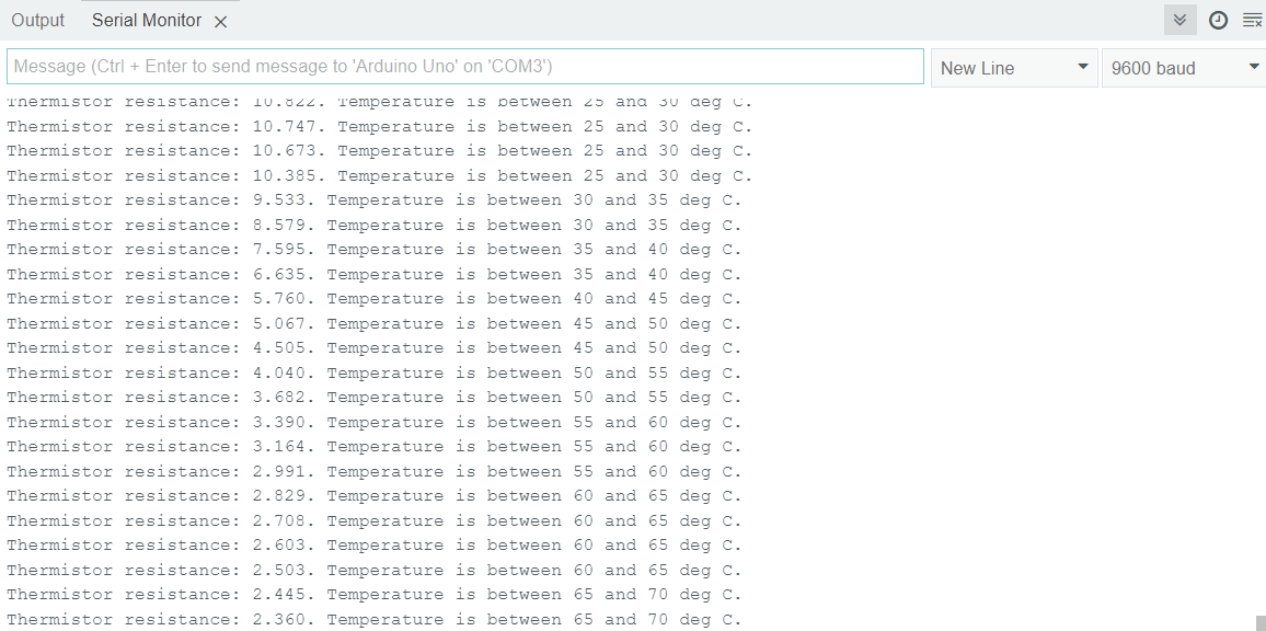
After starting you should see similar output on the serial monitor:

image

For an experiment I tried to place thermistor to the cup of hot water like I did in previous part and output changed as expected:

image

Summary

This is all from this blog post. Thank you for reading it. In this blog I shown and described very simple method of measuring resistance of Molex thermistor using Arduino and implemented very simple conversion of this resistance to the temperature. Program was very minimalistic and later I will use more advanced and accurate approaches of measuring temperature using thermistor. In next blog post and third part of this thermistor tutorial series I will use the same measurement circuit, but for computing temperature I will use Steinhart-hart equation instead of lookup table which I used in this program. Below this paragraph you can download Arduino sketch which I created as part of this minitutorial. Constants and temperature in the sketch are computed for 215272-3707 thermistor. It is thermistor #8 from the kit used as part of this contest. It is the only thermistor with red wire and blue epoxy in the kit. Running the program with different thermistor connected will result to wrong values. If you want to use different thermistor, than you need to replace temperature and resistance arrays.

Thank you for reading this blog post. I welcome any feedback, so feel free to comment about this tutorial in comments below.

Resources

  • Arduino Sketch
  • Sign in to reply

Top Comments

  • shabaz
    shabaz over 3 years ago +3
    Hi, It may be worth increasing the resistance, because 2.2 k ohm is rather low. With 5V across the circuit, there is power dissipation of several mW depending on the temperature, and this will result…
  • misaz
    misaz over 3 years ago in reply to shabaz

    Thank you for valuable feedback. Approach shown in this blog is very minimalistice. There are many caveats that can significantly reduce accuracy and self-heating is one of the sources of inaccuracy. I realise following sources of error to the measurements:

    • Measurement accuracy is strongly dependent on accuracy of reference resistor. This is resolvable by using more accurate resistor.
    • Measurement accuracy is strongly dependent on powering voltage of Arduino which I consider even bigger poroblem than previous point. This can cause different readings depending on power supply used. For example you can get different reading when Arduino is powered by different computers because voltage on USB ports of two computers can be sifferent. This is for example resolvable using voltage reference. (If I remember correctly ATRmega used on Arduino has some internal references but I never used them on Arduino, but it is worth to check on this).
    • Build-in 10-bit ADC in AVR MCU is not the best one. I am not sure if Arduino code use CPU sleep mode for noise reduction, but even it does, then external ADC can still be better coise.
    • Self-heating as you mentioned is issue. I will describe why did I chosen 2k2 below.

    So level of inaccuracy is based on tolerance of thermistor, resistor, self-heating, ADC INL and DNL, noise and most probably some others which I did not realized yet.

    The reason for choosing 2k2 was ADC codes utilization. I selected it by defining range in which I want to measure temperature as 0 to 110 °C. I supposed that water in my cup will never be heated to more than 110°C and also it never fals bellow 0°C. For this temperatures I took resistances from datasheet (38.73kOhm@0°C and 0.581kOhm@110°C). For this resistances I simulated (in MS Excel) voltages on ADC at both temperature levels for multiple reference resistor values:

    image

    For example look at 100k collumn. 100k resistor reduce self-heating significantly, but voltage at ADC input would be between 3,6V@0°C and 4,9V@110°C, so voltage on ADC. This means that only 27% of ADC range 0 - 5V would be utilized because I will never measure voltages below 3.6V (and above 4.9V). From this simulation I selected value between 1000 and 10000 ohms which resulted to about 73% ADC codes utilization and finally to the better resolution. But disadvantege is higher self heating effect.

    Note that it is possible to find the best fit resistor in terms of ADC codes using math. At best resistance value derivation of function substracting voltages at borders of required range is equal to zero, but my resistor box most probably will not contain resulting resistor value, so I cohoosen experimental approach and simple Excel rather.

    • Cancel
    • Vote Up 0 Vote Down
    • Sign in to reply
    • More
    • Cancel
  • misaz
    misaz over 3 years ago in reply to DAB

    Good question. Precision of chinese resistor used is experiment is unknown, most probably low. It looks like 1%. For real usage I recommend more accurate resistor, but I have only SMD resistors with better tolerance. I measured it as 2.184kOhm and in experience time I used 2184 constant in program instead of 2200, but before making screenshots and publishing code I reverted it back to 2200 for making them less confusing. Similarly I updated VCC constant from 5V to 4.6V.

    • Cancel
    • Vote Up 0 Vote Down
    • Sign in to reply
    • More
    • Cancel
  • DAB
    DAB over 3 years ago

    Nice basic test.

    Did you measure the actual resistance of the 2.2K ohm resistor or are you just using it stated value?

    What is the precision of the 2.2K resistor?

    • Cancel
    • Vote Up 0 Vote Down
    • Sign in to reply
    • More
    • Cancel
  • shabaz
    shabaz over 3 years ago

    Hi,

    It may be worth increasing the resistance, because 2.2 k ohm is rather low. With 5V across the circuit, there is power dissipation of several mW depending on the temperature, and this will result in the thermistor self-heating, causing errors of several degrees perhaps (on the other hand, this may be acceptable on the use-case, so this is just informational).

    • Cancel
    • Vote Up +3 Vote Down
    • Sign in to reply
    • More
    • Cancel
element14 Community

element14 is the first online community specifically for engineers. Connect with your peers and get expert answers to your questions.

  • Members
  • Learn
  • Technologies
  • Challenges & Projects
  • Products
  • Store
  • About Us
  • Feedback & Support
  • FAQs
  • Terms of Use
  • Privacy Policy
  • Legal and Copyright Notices
  • Sitemap
  • Cookies

An Avnet Company © 2025 Premier Farnell Limited. All Rights Reserved.

Premier Farnell Ltd, registered in England and Wales (no 00876412), registered office: Farnell House, Forge Lane, Leeds LS12 2NE.

ICP 备案号 10220084.

Follow element14

  • X
  • Facebook
  • linkedin
  • YouTube