For this Experimenting With Thermistors challenge, element14 and Molex provided us with a kit of 10 different thermistors to experiment with. After experimenting and researching for the last few months, I wondered if perhaps not all of them are as equally suited to my specific task.
For my project, I hope to track temperature of my hummingbird feeder and the air near it.
I live on the West Coast of Canada, where temperatures should never be lower than -20degC or higher than +40degC, so I want to “tune” my application to be most accurate for the middle of that range.
The thermistors come with data sheets that show how their resistance varies with temperature, so my first step is to pick out two or three thermistors that have the best resistance change for the range of temperatures I’m interested in.
Because of the way the nectar bottles curve, I have chosen to eliminate the first 3 thermistors that have the ring terminals, as they are not as easy to get up close to the glass as the epoxy coated ones are. I would imagine the ring terminals are best suited to circuit board applications where they can be mounted onto a heat sink, for example.
That leaves me with 7 thermistors to choose from, ranging from 3k to 47k nominal resistance.
I decided to try to graph them for my temperature range, to see which ones have the most resistance difference for my desired sensing range.
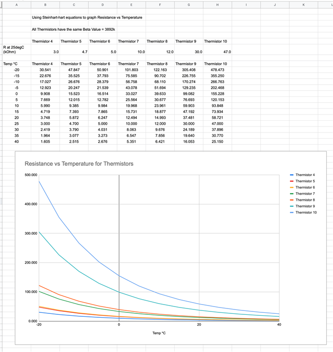
To graph them, I used a spreadsheet to calculate the resistance values for each thermistor using the Steinhart-hart equations.

The picture shows the formula used to calculate the resistance for each thermistor for each temperature. You can double-check the results by comparing the row for 25 degrees C with the nominal resistance for each thermistor (they match!)
From there I was able to easily create a graph that helps me visualize the curves.

I'm actually not 100% sure how to interpret that chart.
The ideal situation would be a straight sloping line for the desired temperature range, but none really do that, which is expected for thermistors.
I want to make sure that the resistance differences are not too small to measure at the higher temperatures in the range, but also that they are not too large for the lower temperature part of the range (making the other part less accurate).
My hunch says that thermistors 7 and 8 are the likely best candidates, as they fall in the middle of the range, providing enough difference across the range without favouring just a portion of it.
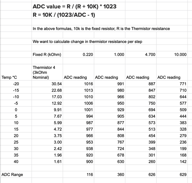
So I decided that a bit more math might be helpful: calculate what the expected ADC value will be from the thermistor resistance over the temperature range, and figure out which thermistor gives the largest ADC range.
I created a spreadsheet for this so I can easily adjust the fixed resistance values of the voltage dividers and see the results.
Side Note: By "ADC value" I mean the value the software reads when using "AnalogRead". For the Arduino Uno, and also for the Wemos D1 Mini I'm using, the range is 0-1023.
Here is my first chart, taking thermistor 4 and calculating the ADC readings over my expected temperature range. Notice how the choice of fixed resistor makes an enormous difference in the ADC resolution we can get. For this thermistor, a 220k fixed resistor only gives us 116 ADC steps over the temperature range, where a 10k resistor provides 629 steps.

Now that I had the spreadsheet formulas figured out, I was able to change the resistors in the column headings to tune towards the best results for each thermistor. I referenced a basic "standard resistor values" chart to make sure I didn't end up with some odd choice in the end. I bet there's a way to just calculate the optimal resistance values using a more complicated formula, but I decided this way was good enough and quick enough.

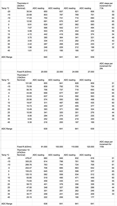
As you can see in the above picture, to my surprise there is an optimal fixed resistor value! For these values, the ADC range peaks when using a fixed resistor of around 7k and then goes down again. Note that the best ADC range for my application is not actually the resistance that matches the thermistor's nominal resistance.
I then repeated the process for the other thermistors.
The first thing I wondered about is whether the other thermistors would all be able to get similar ranges.
The second thing I wondered about is whether the overall range is similarly distributed over the temperature range, for the different thermistors.
Interestingly enough, I found that I was able to tune the smallest-resistance thermistor (thermistor 4) to get the same ADC range as the one with the highest nominal resistance (thermistor 10) - in both cases 641 steps. The result for thermistor 7, in the middle of the group, was the same too. Even the maximum and minimum ADC values come out nearly identical. They also happily avoid the extreme ends of the ADC range (avoiding being near 0 as well as 1023), which are known to be less accurate.
That answers my first question - in terms of ADC range, it doesn't matter which thermistor I choose, as long as I pick the right fixed resistor for the voltage divider.
However, my second question remains - how similar are the steps in the ADC range for each thermistor, for their optimal fixed resistor?
Oddly enough, when using the optimal voltage divider resistor (as calculated previously), even the ADC steps per increment are nearly identical across the entire range!

So now I am completely confused! Maybe my desired temperature sensing range just happens to be in a sweet spot where it doesn't matter which thermistor I'm using?
Maybe thermistor choice depends more on the Beta values?
Or is it that the point of the various resistance values has to do with other factors that I don't need for my specific application?
I think, for my project, I'll just use thermistors 7 and 8, which have a nominal resistance value in the middle of the range we were provided. I might have to adjust depending on what resistors I have available in my kit :)
If anyone has insights as to what I might be missing here, please do share!
-Nico
EDIT:
After much more research into voltage dividers, I stumbled across a way to simplify selection of the fixed resistor (found it on StackExchange). It comes down to a very simple equation, taking the "geometric mean" of the thermistor's maximum and minimum resistance values for the desired sensing range.
The ideal fixed resistor = Square root of ( Thermistor_Max_Resistance * Thermistor_Min_Resistance )
I tested this with the above 3 thermistors, and it matches the results that came out of my long tables:
For my desired temperature range, the geometric mean, ideal fixed (bias) resistor for...
...Thermistor 4 = 7.01 kOhm
...Thermistor 7 = 23.34 kOhm
...Thermistor 10 = 109.70 kOhm
I think this will be helpful to anyone else trying to tune their voltage dividers to their own applications!

