This last week or so I've been experimenting with a way to read temperatures from multiple thermistors.
But First... before we talk about thermistors some more, let’s hear it for the case they came in, ok? These things are often overlooked, but I was just admiring it today, and also the fact that the compartments have solid divisions between them. Anyone who’s had tiny parts migrating and mingling can appreciate that detail. The lid properly overlaps and interlocks with the bottom too, to keep things from falling out, and it has actual hinges! - not just thinner bits of bendy plastic. Aaaah. It’s the little things in life that make the difference! Like a good cup of coffee.
But I digress… let’s talk about thermistors!
After my success with a single thermistor I gained so much confidence that I decided to go wild, and plonk ALL of my thermistors onto a breadboard! Scary, right? What am I getting myself into? You’re probably wondering how this is going to turn out, aren’t you? Oh the suspense!
My original plan was to connect a few good candidates onto my ESP2866 board and have it report data back to my Raspberry Pi server, ultimately making a nice multi-line graph. But, sadly, as it turns out, the ESP8266 can only handle one analog input at a time (unless we employ some fancy and sneaky methods). So that plan has been set aside… for now.
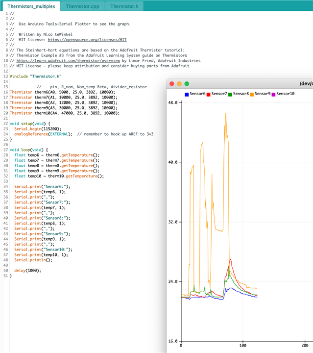
Thankfully, the Arduino IDE has a built-in Serial Plotter that turns out to be super handy for exactly the testing I was planning to do. By simply printing the temperatures to the Serial output, the plotter can turn it into a nice line graph. And it even handles multiple sensors to provide a very lovely multi-line graph!
Now, those of you paying careful attention will have noticed that I have all 10 thermistors on that breadboard, but only 5 of them are hooked up to the Uno. Unfortunately, the Uno can't handle all 10 at once. That's usually not a problem, as a normal everyday project is not likely to need that many analog inputs.
The Arduino Uno I’m using has 6 analog inputs, so I thought it best to run my tests in 2 groups.
Handling multiple thermistors can lead to some very cluttered software if it's not built in an organized sort of way, so I decided to build a Thermistor Object to represent each physical thermistor. Then I could just initialize an object with the resistance and beta values, and the object keeps track of the details itself after that. Much easier than looping through arrays of various values every time we want to do something with a thermistor.
I'll share all the code in my final blog post, which is coming soon. (I hope! )
The most frustrating part was, of course, when I made a "tiny" change in the code while organizing it into an object... and accidentally changed the math of the crucial formulas.
I eventually found, and fixed, the mistakes and the result is that it is now super easy to set up and use an analog pin with a thermistor!
Now I was able to easily run multiple sensors at once, to compare them.
I had planned to do some more detailed experimenting, in 2 batches, measuring the temperature of water cooling in a bottle, to get a feel of which thermistors would work best for my hummingbird feeder monitoring project, but I quickly noticed some oddities in my results - the Arduino Serial Plotter made it very easy to notice.

For the testing I would touch the thermistors to see the graph going up and down a bit. The idea was just to get a basic graph at first, mostly testing the graphing.
However; when I barely touched sensor #9, or even just brushed it, the graph would spike the temperature far out of the expected range. Like, I know I'm not that hot.
And I don't even know what happened to sensor #10... the chart legend says it's reporting, but I don't see a purple line.
So this leaves me with a few hypotheses:
1. I was using 10k resistors for all of the thermistor dividers. I think it's probably wise to match the resistor to the value of the thermistor resistance @25 degrees
2. Matching the divider resistor to the thermistor... I -think- that puts the middle point of the ADC range at 25degC. (I mean, the Uno has range 0..1023, so I'm guessing a matched resistor would return 512 at 25degC)
3. Further to 2... I'm guessing that the divider resistor could be tuned to place the mid point of the ADC range to the middle of the desired temperature range. For my desired range of -20 to +40, I'm guessing the ideal mid-point would give ADC of 512 at 10degC.
For thoughts 2 and 3: can someone who is more mathematically inclined... more voltage divider savvy... comment on this? Is my hunch on the right track?
For my next step, I think I'll just concentrate on looking at the provided "resistance vs temperature characteristics" charts to see if I can pick out a few thermistors that will work best for my application.
Oh hey, speaking of divider resistors, that reminds me: in a previous blog post I mentioned that the value specified in code for the resistor could be set to be the exact value of the physical resistor, for a more accurate result.
So I tested my 10k resistors... wow, I think I can live with that accuracy!

