


My plan is to use the vibration sensor to perform vibration analysis of a motor. Rotating machinery produces vibrations that depend on their structural properties. One important component of rotating machinery are the bearings. Ball bearings produce a vibration signature that depends on bearing properties (ie: number of balls, diameter of the balls, the inner and the outer race, etc). By analyzing the vibration signature it is possible to identify what exactly is damaged, and how damaged it is. To perform these analysis the time series have to be converted from time domain to angular domain (this conversion process is called order tracking). The spectrum in the in the angular domain then indicates the kind of damage (seen as a frequency component) and the amount of damage (seen as the amplitude of the peak).
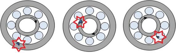
The next image shows a damaged outer race, inner race and ball respectively:
My plan is to build a system to perform vibration analyses in realtime. The system will be made of a motor, the sensor attached to the motor, a way to measure the rotational speed, a data acquisition system and a computer that will run the software that will perform the analyses.
How exactly I will implement the system, I still have to decide.
Here are some possibilities that I'll have to evaluate
Motor:
- A grinder, that generates a lot of vibration (specially when it runs at its natural frequency during initial acceleration when turning it on). II was able to measure its rotating speed using a photodiode and a laser. The drawback of the motor is that I can't easily control the speed of the motor.
- 4-pin computer fans. They allow easy control of the rotational speed and come with a tachometer pin, but generate very little vibration, and usually don't use ball bearings.
- Quadcopter brushless motors. Their speed can be controlled through an electronic speed controllers (ESC), mine don't come with a tachometer so I would have to measure the rotational speed in some way.
Tachometer:
- Tachometer line is the simplest way, but could only use this with the 4-pin computer fan.
- Laser/photodiode tachometer work well but require a robust structure to keep everything in place.
- The ESC signal probably gives me the highest resolution as the signal oscillates multiple times per revolution.
Data acquisition system:
- NI MyDAQ can sample at 200 ksps @ 16 bit, can be interfaced to LabVIEW really easy, but comes only with 2 channels. This might suffice if I decide to just sample the vibration and rotational speed signal though. One relevant drawback though is that it can't generate a PWM signal, which I would need if I want to control the motor speed.
- STM32H7 Nucleo board can sample at 3.6 Msps @ 16 bit, but will require more work to program it, encode the data and stream it to LabVIEW (if I decide to use it). Another drawback is the virtual serial port to the computer could limit the capturing speed. There is an Ethernet port and Bluetooth, but these have their own challenges.
Software:
- LabVIEW makes it easy to build an instrument GUI, but programming the data processing part may be more difficult.
- Python makes it easy to program the data processing part, but harder to design an instrument GUI.
In the upcoming weeks I'll experiment with the sensor and post what I find out, I'm sure it will be fun!
Top Comments