For my project I am using 4 of the 7 connectors in the kit. 3 of those connectors will require wiring of an adapter to the panel connector and 2 of them will also require wiring to the mating connector. This post details how the connectors are wired and tested.
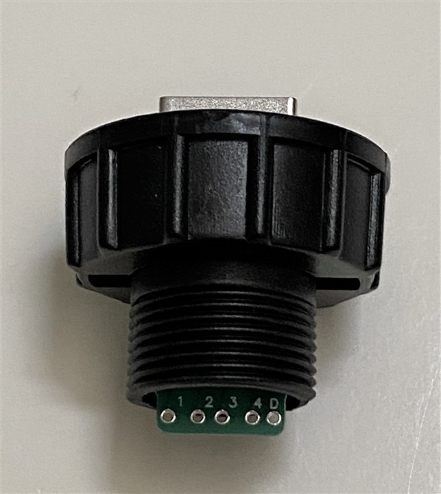
I found it interesting that these industrial connectors are fairly Spartan in terms of labeling. In the case of the RJ45 interface board there were no pin numbers associated with the terminal blocks, so I needed to do a continuity check before I connected the cable pigtail. For the USB-A plug board, the pins were labeled 1-4 and D, so again a continuity check was required. I'm used to consumer products that are more obviously labeled, so I created my own connection tables.
RJ45 Jack
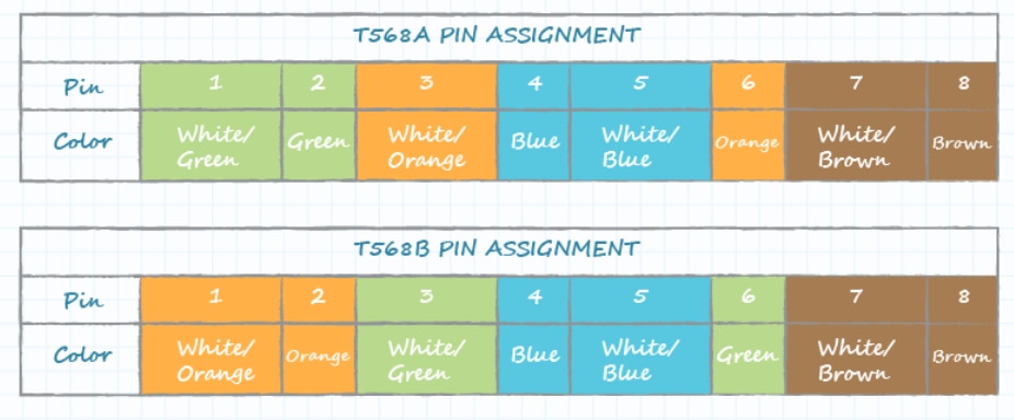
RJ45 T568B Cable
Terminal Block Top View
|
8 Brown |
1 White/Orange |
|
7 White/Brown |
2 Orange |
|
6 Green |
3 White/Green |
|
5 White/Blue |
4 Blue |
|
NC |
NC |


The finished connector assembly.

A video showing the assembly test using a cable tester.
USB-A Jack
USB
|
1 |
Red +5V |
|
2 |
White Data+ |
|
3 |
Green Data- |
|
4 |
Black Gnd |
|
D |
Shield |
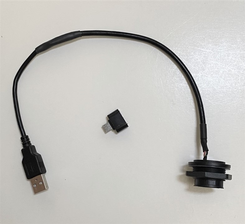
The USB panel connector with its pigtail and mating connector attached.

The mating connector PCB connections.

Cable grommet is for 3.5mm to 6.8mm cable. I am using an external USB 3.0, 5.5mm diameter cable
The completed internal cable assembly. I also have a USB-A to microUSB adapter, so that I can use the USB as a standard port or to provide power to the lattePanda. I've used shielded cable internally and externally, so it should work for USB 3.0.

4 Pin Circular
I am using the 4 pin circular connector for power and an external thermistor. The pin assignments are shown below.
|
1 |
RED +5V |
|
2 |
Black GND |
|
3 |
Yellow T- |
|
4 |
White T+ |
Male Cable connector looking into socket contacts

Cable grommet is for 4.0 to 7.0mm cable. I am using an external 4.5mm cable.
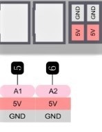
The completed internal cable assembly. I attached Dupont connectors to the lattePanda end of the cable. The power goes into the CN2 header and the thermistor is on the adjacent header connected between +5V and A2. I will add the pulldown resistor to ground at the header. The internal thermistor will be on A1.


I'm waiting to receive the waterproof RJ45 boot/backshell assembly that will allow that interface to work submerged (the USB and 4 Pin interfaces should already be waterproof). The RJ45 backshell will require adding a couple of extra holes to the enclosure which hopefully isn't too tricky...
