element14 Community
element14 Community
    Register Log In
  • Site
  • Search
  • Log In Register
  • Community Hub
    Community Hub
    • What's New on element14
    • Feedback and Support
    • Benefits of Membership
    • Personal Blogs
    • Members Area
    • Achievement Levels
  • Learn
    Learn
    • Ask an Expert
    • eBooks
    • element14 presents
    • Learning Center
    • Tech Spotlight
    • STEM Academy
    • Webinars, Training and Events
    • Learning Groups
  • Technologies
    Technologies
    • 3D Printing
    • FPGA
    • Industrial Automation
    • Internet of Things
    • Power & Energy
    • Sensors
    • Technology Groups
  • Challenges & Projects
    Challenges & Projects
    • Design Challenges
    • element14 presents Projects
    • Project14
    • Arduino Projects
    • Raspberry Pi Projects
    • Project Groups
  • Products
    Products
    • Arduino
    • Avnet & Tria Boards Community
    • Dev Tools
    • Manufacturers
    • Multicomp Pro
    • Product Groups
    • Raspberry Pi
    • RoadTests & Reviews
  • About Us
    About the element14 Community
  • Store
    Store
    • Visit Your Store
    • Choose another store...
      • Europe
      •  Austria (German)
      •  Belgium (Dutch, French)
      •  Bulgaria (Bulgarian)
      •  Czech Republic (Czech)
      •  Denmark (Danish)
      •  Estonia (Estonian)
      •  Finland (Finnish)
      •  France (French)
      •  Germany (German)
      •  Hungary (Hungarian)
      •  Ireland
      •  Israel
      •  Italy (Italian)
      •  Latvia (Latvian)
      •  
      •  Lithuania (Lithuanian)
      •  Netherlands (Dutch)
      •  Norway (Norwegian)
      •  Poland (Polish)
      •  Portugal (Portuguese)
      •  Romania (Romanian)
      •  Russia (Russian)
      •  Slovakia (Slovak)
      •  Slovenia (Slovenian)
      •  Spain (Spanish)
      •  Sweden (Swedish)
      •  Switzerland(German, French)
      •  Turkey (Turkish)
      •  United Kingdom
      • Asia Pacific
      •  Australia
      •  China
      •  Hong Kong
      •  India
      •  Japan
      •  Korea (Korean)
      •  Malaysia
      •  New Zealand
      •  Philippines
      •  Singapore
      •  Taiwan
      •  Thailand (Thai)
      •  Vietnam
      • Americas
      •  Brazil (Portuguese)
      •  Canada
      •  Mexico (Spanish)
      •  United States
      Can't find the country/region you're looking for? Visit our export site or find a local distributor.
  • Translate
  • Profile
  • Settings
Design Challenges
  • Challenges & Projects
  • More
Design Challenges
Forum Mosfet heating
  • Forum
  • Documents
  • Polls
  • Files
  • Mentions
  • Sub-Groups
  • Tags
  • More
  • Cancel
  • New
Actions
  • Share
  • More
  • Cancel
Forum Thread Details
  • Replies 5 replies
  • Subscribers 5 subscribers
  • Views 1648 views
  • Users 0 members are here
  • mosfet
  • high voltage
  • heating
Related

Mosfet heating

audrialaa
audrialaa over 8 years ago

Hello Guys,


Currently I am building circuit for high voltage discharge.

I am controlling signal using two dual channel mofsets and supplying them to the transformer ( 100 voltage multiplication).


PROBLEM 1: mosfets become very hot and I am afraid that after some time they will get damaged.

PROBLEM 2: If I put diode STTH11A the volatge output becomes very low., less than 100V.

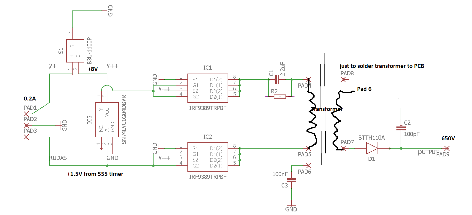
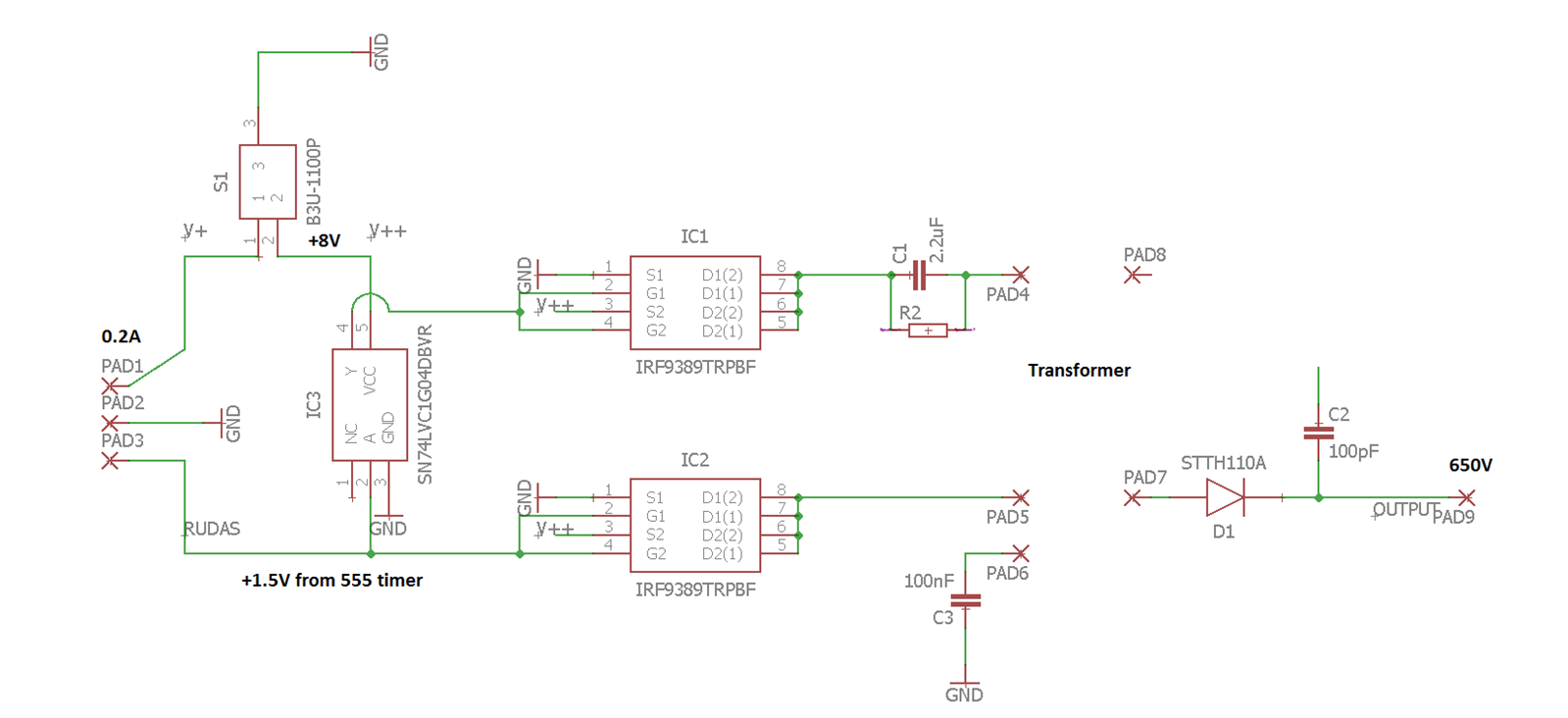
Part of the circuit (circuit for 555 timer is pretty simple, works in abstable state  - not showed):


The SN74 is an single inverter, IRF93 Dual channel mosfets.
image


Any advices where the problems could be ?

PS: Yes I know cap in the end doesn't do anything image


Thanks for help in advance image


BS,

A

  • Sign in to reply
  • Cancel
Parents
  • e14 Contributor
    e14 Contributor over 8 years ago

    P channel and N channel MOSFETS are basically opposites. You are trying to drive it both on and off at the same time by trying to use them in parallel. In addition, power MOSFETS have an intrinsic body diode, which is also hurting you. (When one MOSFET is on, the other is conducting through the body diode.) By using them in parallel, they would also attempt to be on, whether the input was high or low. (Well, either the P or N would always be on, depending on the input voltage - high or low.)


    You need to use the part with only one side of it or the other, not both tied together. (Alternatively, you could use both sides, but you still can't tie them together like that.) D1 and D2 should not touch like you have them. Potentially, based on the circuit, you could have G1 and G2 tied together, but you really need to understand how these work and be sure that it's how you want to be controlling it.


    If any of that isn't clear, let me know and I can try to explain further. I don't see enough of the circuit to be able to say anything about the diode on the transformer and why it's doing what it is. The different traces going to a pad number aren't clear what they would be doing.

    • Cancel
    • Vote Up +5 Vote Down
    • Sign in to reply
    • Cancel
Reply
  • e14 Contributor
    e14 Contributor over 8 years ago

    P channel and N channel MOSFETS are basically opposites. You are trying to drive it both on and off at the same time by trying to use them in parallel. In addition, power MOSFETS have an intrinsic body diode, which is also hurting you. (When one MOSFET is on, the other is conducting through the body diode.) By using them in parallel, they would also attempt to be on, whether the input was high or low. (Well, either the P or N would always be on, depending on the input voltage - high or low.)


    You need to use the part with only one side of it or the other, not both tied together. (Alternatively, you could use both sides, but you still can't tie them together like that.) D1 and D2 should not touch like you have them. Potentially, based on the circuit, you could have G1 and G2 tied together, but you really need to understand how these work and be sure that it's how you want to be controlling it.


    If any of that isn't clear, let me know and I can try to explain further. I don't see enough of the circuit to be able to say anything about the diode on the transformer and why it's doing what it is. The different traces going to a pad number aren't clear what they would be doing.

    • Cancel
    • Vote Up +5 Vote Down
    • Sign in to reply
    • Cancel
Children
  • audrialaa
    audrialaa over 8 years ago in reply to e14 Contributor

    Thanks for an answer and explanation of dual mosfet. This is the firt project I am trying to use them and this scheme is barrowed from other device. Now I understand why this device stops to work after some time and you need to take it to warranty. Is funny, as that device is  CE certified and even getting new one it breaks - at most it keeps for two month. Seems that somebody wants to earn some extra money..


    So, in general to drive the transfomer I should use just P channel on both mosfets and I need to delay one of the signal so that the transformer could work (induce). I am correct ? As the single inverter inverts the signal from the timer and supplies it to second mosfet (timer gives pulse signal from 0V to +1.5V).

    image

    • Cancel
    • Vote Up 0 Vote Down
    • Sign in to reply
    • Cancel
element14 Community

element14 is the first online community specifically for engineers. Connect with your peers and get expert answers to your questions.

  • Members
  • Learn
  • Technologies
  • Challenges & Projects
  • Products
  • Store
  • About Us
  • Feedback & Support
  • FAQs
  • Terms of Use
  • Privacy Policy
  • Legal and Copyright Notices
  • Sitemap
  • Cookies

An Avnet Company © 2026 Premier Farnell Limited. All Rights Reserved.

Premier Farnell Ltd, registered in England and Wales (no 00876412), registered office: Farnell House, Forge Lane, Leeds LS12 2NE.

Follow element14

  • X
  • Facebook
  • linkedin
  • YouTube