


The EnOcean Sensor Kits we received as contestants for this challenge included 3 sensors. One is the PTM 210 Pushbutton Transmitter Switch Module, the other two are an STM332 Temperature Sensor Module and the STM 329 Magnet Contact Transmitter Module. While this is a design challenge and not a teardown, I still wanted to explore the possibilities a bit more with these sensors and find out if I could use them in a different way than intended.
First I wanted to compare the two STM3xy modules and see what the difference was between them. The most obvious difference is that the STM332 has a very small pitch (1.25 or 1.27mm) 20 pin header attached to the board with a jumper over a pair of pins, and the STM329 has a reed relay attached to the board. The header on the STM332 is for adding an optional humidity sensor to the module, however if reconfigured the module will support additional features, exposing IO lines and analog inputs.
STM332 Temperature Sensor Module

STM329 Magnet Contact Transmitter Module
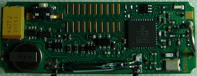
I overlaid the images across each other and made an animated gif that switches back and forth. The only other standout change aside from the antenna (whip vs helical) that I noticed is that the STM332 also has an additional transistor and what looks like a capacitor to the right hand side of the pin header.
The chip on these appear to be a Maxim SD317 ultra low power energy harvesting RF Tx for below 1Ghz, I can't find any additional details or datasheets on these other than the one page that said what they were, so I'm wondering if perhaps they came from Maxim's custom ASIC design services or are a top secret design with non-discolsures and all that good stuff.
I wanted to find out how the temperature was sensed on the STM332, I was somewhat hoping that there was an external thermistor or something along those lines. This would mean that one might be able to remove the thermistor and inject another carefully crafted signal in there. I placed my finger across the chip and pushed the teach-in button to send the current status, as my finger rested there the temperature steadily rose. When I took my finger away it cooled down, I'm pretty sure that the temperature sensor is built into the main processor. I also tried warming up the transistor device next to the header but that seemed to have no effect, I was thinking maybe it was a temperature sensing diode.
It seems that with the temperature sensor as is there is not much hacking to be done. More flexibility can be revealed by re-configuration.
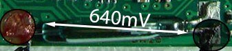
Next up was the STM329 Magnetic Contact Transmitter Module. This board doesn't have the header, it just has a reed relay. I measured 640mV between the left pin and the right lower pin. It's either actually ~640mV or there is a high value current limiting resistor and the load of my meter is pulling the voltage down, I don't have a Hi-Z (high input impedance) setting on my meter at home.
I attached a couple of flying leads to either contact point on the reed relay and attached a variety of switches to it. They all worked when connected, but I did notice that RF noise from the small relay would cause the sensor to false trip. I'm willing to bet aflyback diode across the coil and connecting all three leads to the relay would cure that.
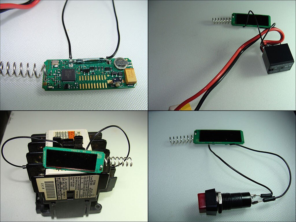
I also tried to see if the magnetic field from the small relay coil was able to trigger the reed switch on the EnOcean module. With the black relay energized I wiped the reed relay along the 5 exposed surfaces but I could not get it to close, I guess in this case the magnetic field is not strong enough, but other relays or solenoids may do the trick.
I would not bother to run long lines from the reed relay, with the voltage so low as it is, any additional resistance could quickly bring it down even lower and prevent it from working reliably.
Finally I took the switch apart and poked around inside there a little bit. It is not difficult to disassemble. The top rocker lever comes off, there are 4 capture points which can be released with a screwdriver and then the top shell can be carefully snapped free with some persuasion.
In the top right corner is the silicone rubber keypad. On the bottom right is the cap, with the button shields and return spring for the energy bow (the yellowish colored lever). On the bottom left is the main board for the switch with the 4 switch pads. You can see the ECO 200ECO 200 energy harvester module aka the 'Electrodynamic Energy Converter' beneath the circuit board.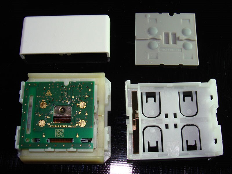
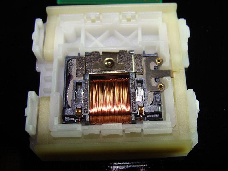
Here's a better view of the ECO 200 energy harvester. There is a piece on the right shaped like an E when the middle leg is pressed down it generates and electrical impulse in the coil which exits at the two gold contacts near the bottom of the coil, the contacts press against the PCB, powering it with each press. I think that's a pretty cool design! The spring is designed to 'snap' the arm on the ECO 200 so i guess it needs a good bump to generate usable power.
Next is the main PCB from inside the switch. You've already seen the back, so let me show you the front. It's design is quite a bit different from the 3xy boards.
The antenna appears to come down on the right hand side and across the bottom, it's been via stitched the whole length. In the upper left hand corner seems to be a 4.7uf capacitor. The chip on the left is a Texas Instruments MSP430 microcontroller and the Texas Instruments CC115L IC on the right is a low voltage/low current mixed frequency range FSK transmitter. I think this is interesting because the STM332 and STM329 sensors are both single chip solutions. There's also a bunch of stuff on the board to finesse the pulses from the EC200 energy harvester into usable power.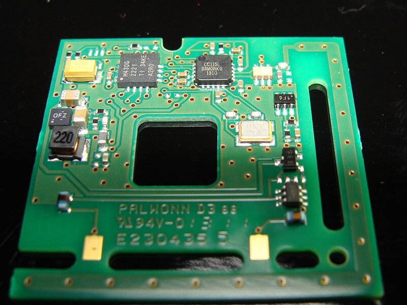
Of course, some of these modules have A2D converters on them and additional digital input pins, it's just a matter of getting them enabled and having support for those features in openHAB. As near as I can tell, so far, openHAB does not currently support a lot of the EEPs (EnOcean Equipment Profiles) but I'm still digging around through the code to see what profiles are supported and trying to find out how hard it is to add more. Perhaps that's what part of this contest is for, generating profile support for openHAB, not sure!
I would like that more features are enabled on these, and to that end I am checking a few options available to change the configurations and I am also looking into the STM300USTM300Uhttp://www.enocean.com/it/enocean_modules/stm-300-data-sheet-pdf/ as it has 4 digital inputs, 2 wake inputs and 3 analog inputs with the default firmware. Oddly the U version is for US the frequency (902.875Mhz), but it's only available from the UK at the moment  The STM300 user's manual is a good read as well. These devices seem to be well documented.
I've been working on the schematic for the data sampling front end of my project and I finally remembered why I needed to order some 1N4448 diodes that I've had in a browser tab for a week Progress is a bit slow as I'm learning where all the parts are in Eagle at the same time vs. Kicad which I normally use. It seems that my like of oddball modules doesn't translate any easier into Eagle and I still have to make a bunch of footprints.
Once I've breadboarded the design, spent some quality time with a quality scope and have determined if the STM300U is going to meet my needs AND if I'll be able to get openHAB to use it, then I will design the PCB, something I've really come to enjoy. Of course I would prefer to stick with the EnOcean products to keep along the theme but I need to keep my options open and may need to find other ways to integrate them into the project. Once I have that going solidly in one direction I will begin to share more details, I don't want to post a bunch of plans for something that may change drastically in a few weeks once the components arrive.
Top Comments