


Thank to the very nice Tracy over at CPC and doctorcdf I was able to get my hands on a couple of sets of RF Sockets to use in my design. Thank you very much Tracy, it was very much appreciated.
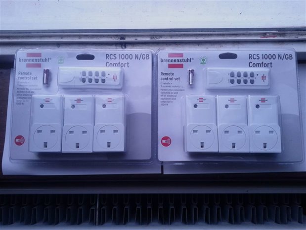
So what did I do with them? Well I did what one of my favorite YouTuber's always says. "Don't turn it, take it apart..." :-)
First I attacked the remote, upon opening it we were presented with a fairly simple PCB and a single though hole IC and a bank of DIP Switches.
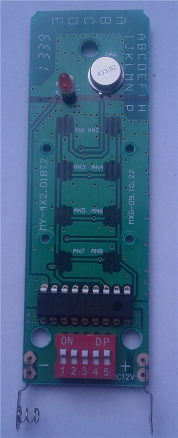
Taking a closer look at the IC shows that it is labeled HX2262. A quick Google later shows that it is basically a PT2262 encoder, another Google later and we have the data sheet. But even without the Datasheet we can reverse this remote. While having the Datasheet will help with reversing this remote there is no fun in that. Lets break out the the scope.
First thing I did was solder a couple of short wires onto pins 17 and 16 to get a better connection to the IC, pin 17 is the data out pin and 16 is the oscillator pin. This allowed me to capture the waveforms created by the encoder chip and replicate them.

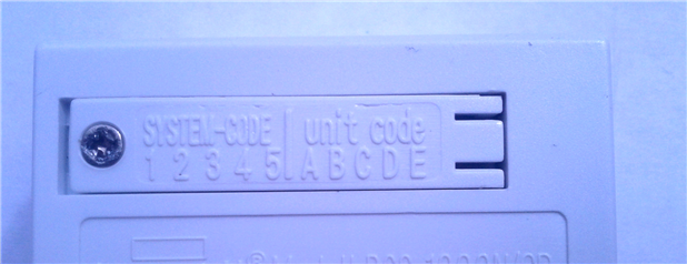
If you read the manual (Blah) the set up for the sockets and remote is fairly simple, The DIP sets the "System Code" and this needs to be matched with the sockets. So lets have a look at the sockets too. On the back of the sock there is a cover that also allows access to some DIP switches.
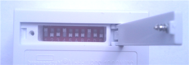
But we have 10 switches instead of the 5 in the remote. It turns out that the last 5 are the "Remote Channel" So if you wanted this socked to answer to the A Channel buttons you would set the A DIP switch to ON. So with a bit of maths we can figure out that this remote offers 128 channels ((2^5)*4). Not that great but I guess its enough for most people. But lets have a look at at the waveforms.
With all the DIP Switches on the remote set to ON a press of the Channel A ON button gives us the following waveform.
Multiple presses of the ON button doesn't indicate that the wave form changes so we don't have to worry about any rolling codes. While this does make the sockets less secure it does remove headaches in reversing the remote. If we didn't have access to the datasheet (For Example: If the remote used a chip on board so was a pain to find out the chip used.) we could use these waveforms to basically preform a replay attack. As I found the datasheet lets "cheat" and have a look what is happening here. (I'll attach the Datasheet if anyone else is interested)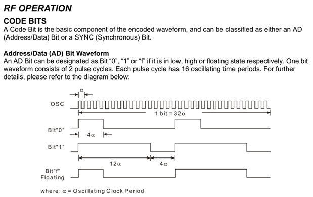
It turns out that this encoder offers Tri-State bits but looking at the waveform the remote only uses low and floating state which makes sense as the DIP switches are single throw and because they use low bits we can presume that the switch is either tied to GND or are left floating. Armed with this lets try and decode the waveform we captured.
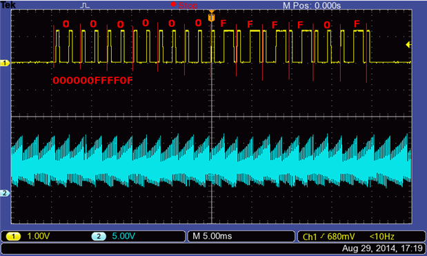
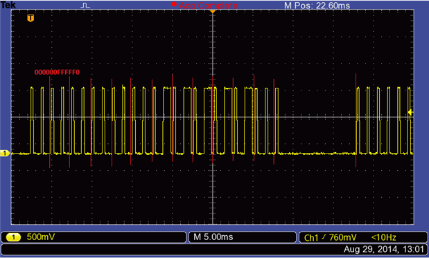
(Forgive the sloppy text) Turns out its easy to decode the data. So with the System Code on the remote set to "ON-ON-ON-ON-ON" (or GND-GND-GND-GND-GND) It turns out that the code for turning on Channel A is 000000FFFF0F. So what about the other channels? Well I won't bore you with the waveforms for the other channels (Unless people ask for them in the comments, then I will upload them) but leaving the System Code to "ON-ON-ON-ON-ON" Channel B ON = 00000F0FFF0F, Channel C ON = 00000FF0FF0F, Channel D ON = 00000FFF0F0F. Hmmm there is a pattern forming here. Lets format this data a bit better.
| Channel A ON | 00000 0FFFF0F |
| Channel B ON | 00000 F0FFF0F |
| Channel C ON | 00000 FF0FF0F |
| Channel D ON | 00000 FFF0F0F |
The Low Bit is shifting along data along with the channel change. As we have already figured out the low bit and I know the remote system code is set to "ON-ON-ON-ON-ON" The first 5 bits must be the System Code. Capturing the waveform while pressing the OFF Button shows that the power state is the last 2 bits of the data.
So we now know that the first 10 bits are the address bits. Its was at this point I had a facepalm moment. Of Course it is, Its only the remote that is limited by its lack of button on its interface, the socket gives us access to all these address bits (I later confirmed this which my "custom remote"). With these 10 address bits we have access to 1024 addresses (2^10) which is a much nicer address space to use than the 128 addresses the remote included in the packs offer.
So lets get cracking on creating our own remote for these sockets. I decided to code my own, There are libraries out there to recreate these remotes but again, where is in the fun in that :-p
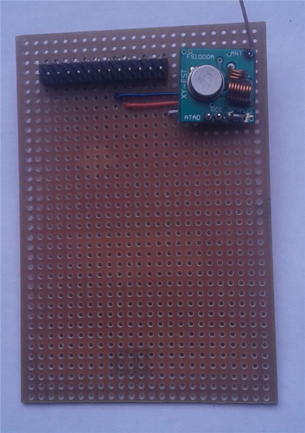
As at the time all my Raspberry Pi's pins were being hijacked by the Enocean Pi I decided to first build a simple remote using an Arduino as its fast to code for. Using a cheap 433Mhz transmitter off eBay (When I say cheap these can be picked up for as little as £1 delivered, although they come via the slow boat from China so I ordered from a seller in the UK, while it increased the price by a whooping 100% it did mean I got the transmitter much quicker and £2 isn't the end of the world) and armed with the datasheet I set out writing a sketch to bitbang the signal.
Reading the datasheet the signal comprised of a "Code Word" which is 10 Address Bits, 2 Data Bits and a Sync bit, This "Code Word" is repeated 4 times and these 4 Codewords make up the Code Frame, This is what we need to replicate. The datasheet breaks down completely how to create the bits, word and frame. The Bits are just counts of high and low of the data pin depending on the clock of the encoder. Using the scope I was quickly and easily able to figure out that each clock cycle of the IC is 100 microseconds. With all this information I was quickly able to produce a sketch that replicated the signal.
This just toggles the power state of a socket with the address of 0F0F00FFFF but it was enough to prove that the remote could be replicated.
Now to add this to the Raspberry Pi. As I said above the Enocean Pi hogs all the pins on the Raspberry Pi A/B and even with the Raspberry Pi B+ extended GPIO there are no power pins on those extra pins. I'm going to hack my way in to get access to the pins. Now a word of warning, the following Pics are gory, anyone who has wielded a soldering iron might be disturbed. My only defence is that I soldered this up at 4 in the morning in a badly lit room. My soldering is not normally this shoddy. We good? Got the kids out of the room? Ok lets carry on.
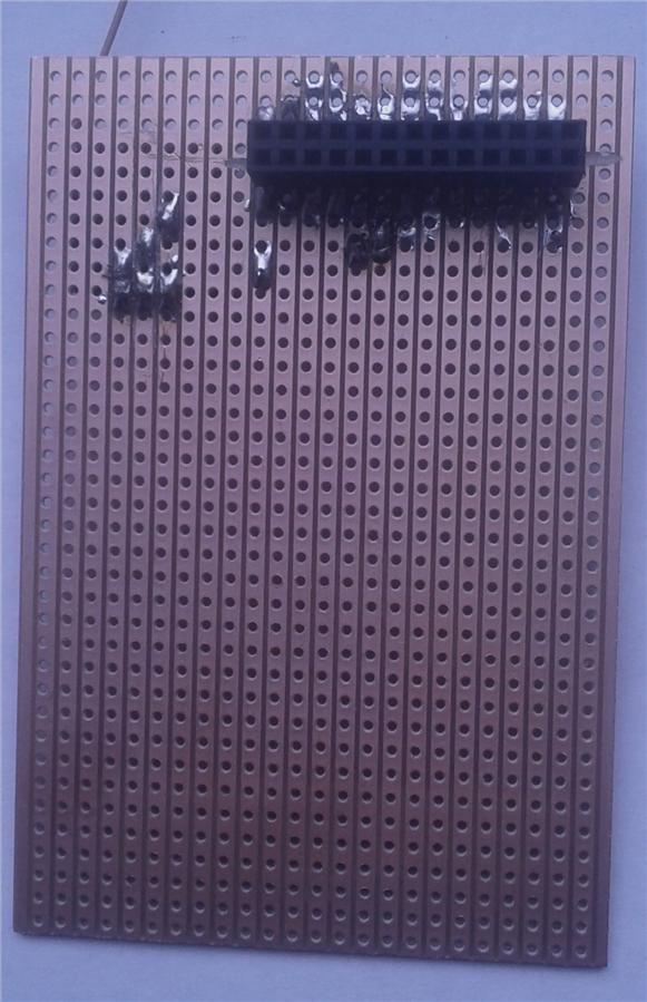
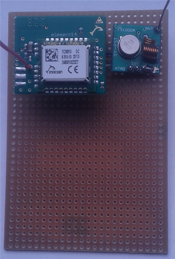
What I did was grab some protoboard. Soldered in 2 header rows, used my dremel to break the tracks between the 2 rows, bend the though hole pins on a 2x13 socket and soldered them to pins on the underside of the protoboard. This protoboard will now allow me a passthrough for the GPIO Pins allowing me to access the IO pins not in use by the EnOcean Pi.
I did consider hacking the EnOcean Pi into having a USB to Serial Convertor but in the end I decided to keep the EnOcean Pi intact. So with this Passthrough board I can easily gain access to 3v3, GND and a I/O pin need to drive the 433Mhz transmitter. The Transmitter is currently powered by the 3v3 rail but it could easily be converted to using the 5v rail and potentially increase the transmitter range, but during my bread board tests the range given by the 3.3 rail covers my home so for now I'm sticking with the 3v3 rail.
Now I have the EnOcean and the Transmitter connected to the Pi at the same time I can work on porting the code I wrote for the Arduino to the Pi. For quickness I created a C based command line program to bitbang out the signal.
So now I have a command line program I can call using:
./program <ADDRESS> <POWER> <REPEAT>
Address being the 10 Bit Address of the Socket, Power being either a 1 or a 0 to send either On or Off and Repeat being how many times the Code Frame is transmitted.
I need still need to work on this program as it needs root (Well as it access the memory map it will always need root, but I could give the program the right permissions so it can be called by normal users), the GPIO Pin is hardcoded and all the arguments are needed where I could use a default repeat count. But its good enough to take it to the next step of integrating it into OpenHab.
In my items file I added some basic switches:
gfdgf
Switch RF_SOCKET_1 "Plug 1"
Switch RF_SOCKET_2 "Plug 2"
Switch RF_SOCKET_3 "Plug 3"
Switch RF_SOCKET_4 "Plug 4"
Switch RF_SOCKET_5 "Plug 5"
In my sitemap file I added some entries of I can access them via the web site:
Switch item=RF_SOCKET_1 label="Plug 1"
Switch item=RF_SOCKET_2 label="Plug 2"
Switch item=RF_SOCKET_3 label="Plug 3"
Switch item=RF_SOCKET_4 label="Plug 4"
Switch item=RF_SOCKET_5 label="Plug 5"
And in my Rules file I added the following:
rule "Plug1On"
when
  Item RF_SOCKET_1 changed from OFF to ON
then
  // Issue Command
  executeCommandLine("/opt/openhab/remotetest 0FF0F00F00 1 5")
end

rule "Plug1Off"
when
  Item RF_SOCKET_1 changed from ON to OFF
then
  // Issue Command
  executeCommandLine("/opt/openhab/remotetest 0FF0F00F00 0 5")
end

rule "Plug2On"
when
  Item RF_SOCKET_2 changed from OFF to ON
then
  // Issue Command
  executeCommandLine("/opt/openhab/remotetest 0F00000FFF 1 5")
end

rule "Plug2Off"
when
  Item RF_SOCKET_2 changed from ON to OFF
then
  // Issue Command
  executeCommandLine("/opt/openhab/remotetest 0F00000FFF 0 5")
end

rule "Plug3On"
when
  Item RF_SOCKET_3 changed from OFF to ON
then
  // Issue Command
  executeCommandLine("/opt/openhab/remotetest 000FF0F0F0 1 5")
end

rule "Plug3Off"
when
  Item RF_SOCKET_3 changed from ON to OFF
then
  // Issue Command
  executeCommandLine("/opt/openhab/remotetest 000FF0F0F0 0 5")
end

rule "Plug4On"
when
  Item RF_SOCKET_4 changed from OFF to ON
then
  // Issue Command
  executeCommandLine("/opt/openhab/remotetest 00FFF0FFF0 1 5")
end

rule "Plug4Off"
when
  Item RF_SOCKET_4 changed from ON to OFF
then
  // Issue Command
  executeCommandLine("/opt/openhab/remotetest 00FFF0FFF0 0 5")
end

rule "Plug5On"
when
  Item RF_SOCKET_5 changed from OFF to ON
then
  // Issue Command
  executeCommandLine("/opt/openhab/remotetest 0FF0FFF0FF 1 5")
end

rule "Plug5Off"
when
  Item RF_SOCKET_5 changed from ON to OFF
then
  // Issue Command
  executeCommandLine("/opt/openhab/remotetest 0FF0FFF0FF 0 5")
end
And saved all 3 files
These rule's look for the item to change and then fire's off my remotetest command line program to send out the command for the sockets. Time to give it a test. (At the last minute my better quality camera decided to it wasn't going to write anything to the SD Card, shacky low quality phone footage it is then)
So as you can see I've managed to get these off the shelf RF Sockets integrated with OpenHAB so they can be controlled though the web interface or through its REST API.
So what else have I been up to?
Programming: I've been working on an Android Application to be able to control and monitor the house from my phone. I've got most of the presence detection system working, just a couple small bugs left to iron out of that and I can crack on with the reporting side of the app.
I've also been working on creating my own PHP based interface with the OpenHAB API to be able to give more finer control. For example allowing users to pull data from the system but restricting the data they can push into the system. I might not mind people getting a 12 hour average temperature of my house but more detailed info about my house temperature and the option to control items in my house needs to be restricted. These are coming on nicely but its all under the hood stuff so nothing to show off just yet.
Hardware: I've been experimenting with creating some wireless modules to put around my house, these are currently based on an Atmel ATMega328 so I have plenty of both digital and analog I/O and I'm using Microchip MRF24J40MA Wireless Modules to communicate with each other and back to the Pi.
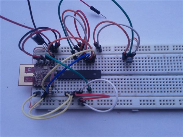
These are very much still in the breadboard prototyping stage as I'm still playing with the code to power them and I'm unsure if I want the wireless modules to be always powered ready to receive commands or have them sleep most of the time to converse power and receive the commands I which them to perform when they check in with the Pi. As I also created a passthrough board for the Pi I can also start work on writing the code to get the MRF24J40MA talking to the Raspberry Pi and inturn talking to OpenHab.
So plenty has been going on in the background, just sadly not much "Eye Candy".
As always drop any questions in the comments and I will happily answer them.
Dan :-)
| pt2262_1.pdf |

Top Comments