


Foreword
Beware, a lot of images, problems, failures (with a mix of success) to follow! Also, written quite hastily, so the text itself might be confusing 
The events following occur during 2 days.
For some reason, my Linux decided that it doesn’t want to create ZIP files compatible with Windows. This delayed the PCB order for 3 or 4 days, but I finally received them on Thursday. Lucky for me, this was also the same day the TBS1052B-EDU oscilloscope arrived from service 
After a brief inspection, the PCBs looked ok, so it was time to assemble them. This is a brief update about that, with a loooot of pictures. As I’m using this project also as a project work to get some ECTS credits for school, I finally managed to document my assembly and related tests quite well. Sorry about the picture quality, all I had with me was my phone…
Starting point
As my own flat is filled with unnecessary stuff (as usual), I decided to use the electronics club "Elko" workspace at the university. It has great facilities for this kind of stuff, starting from few soldering irons all the way to laboratory power supplies, oscilloscopes etc. The workspace is shown in Picture 1.
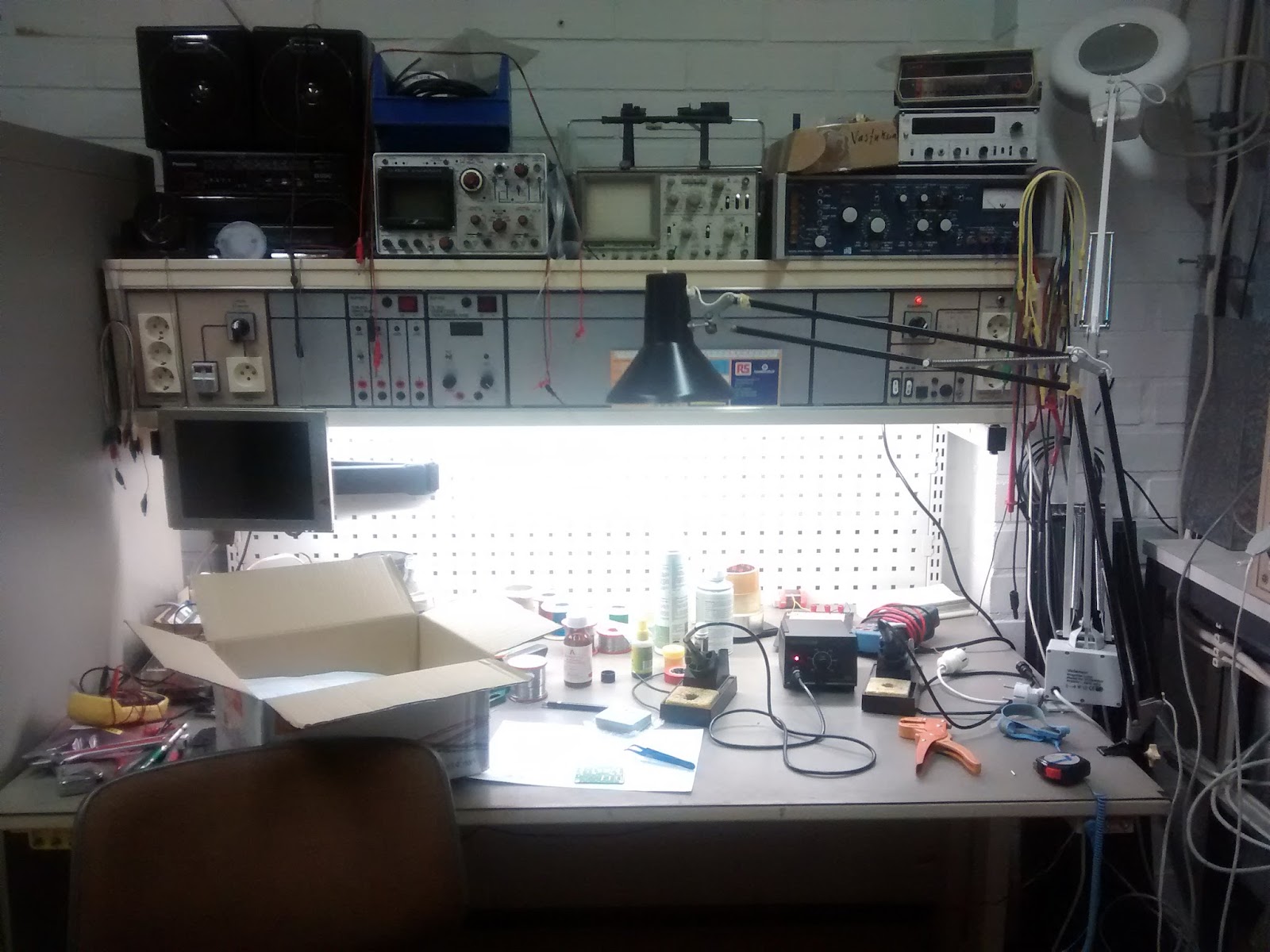
Picture 1: Workspace at Elko
As you can see from the picture, there’s also a lot of historical measurement devices. All of these should be fully functional, although many of them haven’t been started in years…
After setting up the workspace as I want, it was time to get to the main event, assembling the PCB. The “clean slate” is shown in Picture 2, together with the schematics to help with the assembly.

Picture 2: A clean slate
My initial plan was to include the most basic stuff, so at first I installed just the level converter for I2C (PCA9306), DS2482 to check the functionality of I2C network, TPS2034 to test 5V power switching and AP1117 to create 3.3V from 5V. Of course, some capacitors and resistors were also needed, together with test wires for 5V supply. This assembly stage is shown in Picture 3.

Picture 3: Test setup with basic circuitry.
First test
After finishing the basic circuitry, it was time to fire up the scope and power supply. The test setup is shown in Picture 4.

Picture 4: Test setup for power-up
Once I got to the testing, quite rapidly there was a problem, which is shown quite clearly in Picture 5

Picture 5: Voltage measurements of 5V and 3V supplies
The picture is supposed to show 5V in CH1 and 3.3V in CH2. As you can see, it clearly doesn’t. Also, something smelled a bit funny. After a brief “touch-inspection”, the source of problem was the AP1117, used to regulate 5V to 3.3V, running very hot.
The problem was, that I changed the regulator quite late in the design phase. This seemed to be the source of problems, as the 5V and GND of the AP1117 were crossed. As I wanted to get on with the testing, I just unsoldered the regulator, attached a wire for 3.3V and moved on…
Once I had “fixed” this problem, it was time to power up the Raspberry Pi through the board and test the I2C connectivity. Test setup is shown in Picture 6.

Picture 6: Test setup for I2C and RasPi powering
All went well and the Pi powered up. The DS2482 was found in I2C-bus and most important of all, worked consistently and the way it’s supposed to
Assembling rest of the circuitry
After initial tests, it was time to assemble the rest of circuitry. The components include DS2482, resistor network for pull-ups and ULN2803A for relay control, DS1307 for real time clock, a socket for MSP430 microcontroller and most important of all, the connector for Raspberry. The connector with long leads for the Pi hadn’t arrived yet, so I had to install a temporary connector with shorter leads. This meant, that I couldn’t attach EnOcean Pi to the board 
I forgot to take pictures, so there’s only couple of “valid” pictures, shown as Picture 7 and 8 below.

Picture 7: Bottom side of PCB

Picture 8: Top side of PCB, attached to Pi
The pictures above also show my selection for the connectors, above is connector for relays and below power supply, 1-Wire and 5V for external devices. The big blank space is reserved for DC/DC converter circuit.
Testing the full circuit
As the assembly took a bit longer than expected, I didn’t bother with too much testing last night. Just set the time of RTC and powered off the device, so I could check that it kept time with battery as it should. It did.
This morning I resumed work with cutting the traces of AP1117 and replacing them with jump leads. The 3.3V regulator is to power up the microcontroller and as reference for I2C level converter. The ugly fix is shown in Picture 9.

Picture 9: Ugly fix for the 3.3V regulator
Also, I soldered the DC/DC converter circuit. This allows me to power the system with only one supply, anywhere in the range of 7 - 24 volts. Pictures 10 and 11 show the system running with the extreme power supply conditions.

Picture 10: System running with 7 volts

Picture 11: System running with 32 volts
As one can see from the pictures, the DC/DC converter works correctly and 5V voltage does stay in acceptable range. The supply voltage is used as supply voltage for relay coils and allows me to use basically any kind of relays with the system.
Once this was done, of course I needed to test a real relay. And once again, I ran into problems. The relay wouldn’t change state, even if I toggle the output of DS2408. As I have a lot of bad experiences with pull-up resistors, of course this was the first thing to check. The resistor network was ok. After more debugging, I noticed that the voltage going to ULN2803A was only 1.53V. According to the datasheet, it needs at least 3V to switch, an I wasn’t even close.
Thanks to the help of a teacher at the laboratory of applied electronics, we figured out that there must be another resistor between pull-up and ground. And of course, there was. After checking out the ULN2803A datasheet, I noticed that includes resistors, as it’s based on traditional transistors instead of FET-technology. I even simulated this part of circuitry, but didn’t use pull-up resistor, just used a direct 5V/GND -signal to control the simulation.
After a brief calculation, it seemed like replacing the pull-up resistor network with 2.2k instead of 10k was a sufficient solution at this point. All I found, was a 1.5k network, so that’ll do. This doesn’t quite fix the problem, as now I must be careful not to turn on all the relays at once, otherwise current will go over the sink capabilities of DS2408. Picture 12 shows the relay control in action.

Picture 12: Rising edge, measured in between of DS2408 and ULN2803A
As one can see from the picture, edge rise time is quite rapid, taking only about 200 nanoseconds to stabilize. Voltage is around 3.5 volts, which should be enough to toggle the relay under any circumstances.
Also, as I happened to be in a lab, which had a proper desoldering iron with suction pump, I replaced the pin header to the Pi with a version with long leads (just arrived this morning). This allowed me to attach EnOcean Pi without any jumper cables as well.
Improvements on the design
As the circuit does seem to function pretty much as I wanted, there isn’t much to be done to the circuit. I’ll start working on revision A2, which will include fixes needed for the 3.3V regulator and relay control. Fixing the regulator doesn’t need much, couple of re-routes will do, relay control is the harder part. The easy solution would be to add a buffer circuit between DS2408 and ULN2803A, but this does seem a bit stupid…
ULN2803A has a maximum of 500 mA per channel, which goes down to 160 mA with all 8 channels. And these are the absolute maximum values, A LOT of power has to be dissipated through the IC in this case. The need for a big heatsink would be the minimum requirement. There just isn’t space for one.
Better solution would be to try and find an 8-channel MOSFET IC. Not only would this reduce the current consumption of the circuit but also make the design a bit simpler, as there wouldn’t be a need for buffer circuit. Also, MOSFETs tend to handle more current, so the relay choices could be wider. One could even drive some loads through MOSFETs, for example small DC water pumps.
Also, I’d like to include some kind of I2C to USB converter, which would allow the device to be used by hardware other than Raspberry also.
To be tested
The main part, that needs testing is resetting the Raspberry with MSP430. This shouldn’t be a problem though. Raspberry needs to send a “clock signal” generated via Python to the MSP430. If the clock isn’t generated, MSP430 will reboot RasPi. This will also reset all relay outputs, so the system is in a “known state”.
Epilogue
As the circuit isn’t that safe to use, I won’t be releasing the schematic quite yet. Once I find good solutions for the problems, I’ll release it. Picture 13 (finally, the last one), shows the full system with EnOcean Pi attached.

Picture 13: RaspAutomation with EnOcean Pi attached
I’ll start working on the next revision of the design. I really need to find a proper circuit for switching the relay loads, any suggestions are welcome!
Most probably the circuit won’t be ready for the deadline, so I’ll move onto coding. In the next post I’ll show the circuit in action, controlling lighting etc in my flat! For now, I’m off to sauna (one of the control and monitoring targets for the system  ).
).