element14 Community
element14 Community
    Register Log In
  • Site
  • Search
  • Log In Register
  • Community Hub
    Community Hub
    • What's New on element14
    • Feedback and Support
    • Benefits of Membership
    • Personal Blogs
    • Members Area
    • Achievement Levels
  • Learn
    Learn
    • Ask an Expert
    • eBooks
    • element14 presents
    • Learning Center
    • Tech Spotlight
    • STEM Academy
    • Webinars, Training and Events
    • Learning Groups
  • Technologies
    Technologies
    • 3D Printing
    • FPGA
    • Industrial Automation
    • Internet of Things
    • Power & Energy
    • Sensors
    • Technology Groups
  • Challenges & Projects
    Challenges & Projects
    • Design Challenges
    • element14 presents Projects
    • Project14
    • Arduino Projects
    • Raspberry Pi Projects
    • Project Groups
  • Products
    Products
    • Arduino
    • Avnet & Tria Boards Community
    • Dev Tools
    • Manufacturers
    • Multicomp Pro
    • Product Groups
    • Raspberry Pi
    • RoadTests & Reviews
  • About Us
  • Store
    Store
    • Visit Your Store
    • Choose another store...
      • Europe
      •  Austria (German)
      •  Belgium (Dutch, French)
      •  Bulgaria (Bulgarian)
      •  Czech Republic (Czech)
      •  Denmark (Danish)
      •  Estonia (Estonian)
      •  Finland (Finnish)
      •  France (French)
      •  Germany (German)
      •  Hungary (Hungarian)
      •  Ireland
      •  Israel
      •  Italy (Italian)
      •  Latvia (Latvian)
      •  
      •  Lithuania (Lithuanian)
      •  Netherlands (Dutch)
      •  Norway (Norwegian)
      •  Poland (Polish)
      •  Portugal (Portuguese)
      •  Romania (Romanian)
      •  Russia (Russian)
      •  Slovakia (Slovak)
      •  Slovenia (Slovenian)
      •  Spain (Spanish)
      •  Sweden (Swedish)
      •  Switzerland(German, French)
      •  Turkey (Turkish)
      •  United Kingdom
      • Asia Pacific
      •  Australia
      •  China
      •  Hong Kong
      •  India
      • Japan
      •  Korea (Korean)
      •  Malaysia
      •  New Zealand
      •  Philippines
      •  Singapore
      •  Taiwan
      •  Thailand (Thai)
      • Vietnam
      • Americas
      •  Brazil (Portuguese)
      •  Canada
      •  Mexico (Spanish)
      •  United States
      Can't find the country/region you're looking for? Visit our export site or find a local distributor.
  • Translate
  • Profile
  • Settings
Get Closer Wearables Design Challenge
  • Challenges & Projects
  • Design Challenges
  • Get Closer Wearables Design Challenge
  • More
  • Cancel
Get Closer Wearables Design Challenge
Blog Creating the FLORAbrella Circuit
  • Blog
  • Forum
  • Documents
  • Files
  • Mentions
  • Sub-Groups
  • Tags
  • More
  • Cancel
  • New
  • Share
  • More
  • Cancel
Group Actions
  • Group RSS
  • More
  • Cancel
Engagement
  • Author Author: zengirl2
  • Date Created: 7 Aug 2013 2:09 AM Date Created
  • Views 857 views
  • Likes 3 likes
  • Comments 4 comments
  • flora
  • led
  • wearable_tech
  • adafruit
  • arduino
  • get_closer
Related
Recommended

Creating the FLORAbrella Circuit

zengirl2
zengirl2
7 Aug 2013

I've spent the last couple of days reading up on the Adafruit Neopixel RGB LED strips -- especially how to cut them apart and use them in combination.  The FLORA doesn't scare me as much as the strips LOL.  On the Adafruit forum, I've seen mixed responses on dealing with my set-up of sending multiple strips the same code.  One response is "fanning multiple strips from one pin is voodoo" and another is that "four strips should be able to run off one pin".  In my case I have eight strips  (which is a total of 5 meters of lights).  So, I'm not sure if I can do all eight off of one pin, or if I must divide them in half and use two pins.  Then my project becomes further complicated by the color sensor, and more importantly the switch.  I would like to use the tactile switch to cycle through the three lighting scenarios (2 are light patterns and the last is the color sensor).  Finally, the question of whether the largest Adafruit LiPol battery will be able to run the lights is yet another obstacle.  So, rather than attempt another one of my ink circuit scribbles, I decided to learn Fritzing.  If anyone is an electronics wiz, I would certainly love it if you could take a look at my attached Fritz file (photo below is just a preview).  You will notice that I have not even put the switch in yet, as I'm not even sure if the programming can handle it.  Thanks for any help and you know how it is when you start to lose sleep over complicated good ideas.


image

Attachments:
image
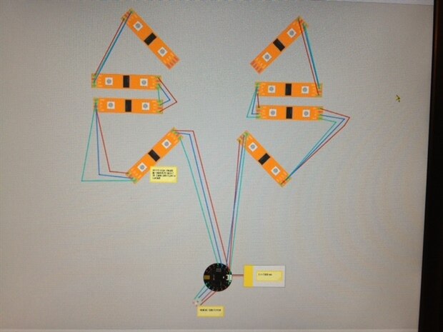
UmbrellaSketch_bb.pdf
  • Sign in to reply
Parents
  • shabaz
    shabaz over 12 years ago

    Hi Leslie,


    It looks like you have the right plan, i.e. chaining DI and DO so that you can extend it, and connecting the DI to any general purpose output pin on the microcontroller board, and splitting it into a couple of banks so that you program the correct colors at twice the speed since the two banks can occur in parallel.

    Each strip contains lots of DI and DOs (i.e. per light) connected together in series anyway, so essentially you're just extending it beyond the strip onto the next strip.

    The fanning method can be fine too (depends on your requirements, and how many to fan).

    Fanning multiple from a single output pin on the microcontroller board would result in the same color scheme on all the strips, which is ok if this is what you want. The frequency that you can control them would have a limit, because of the amout of capacitance that the single pin output on the microcontroller would see (the microcontroller will not be able to toggle the DI pin ultra-rapidly when there is too much capacitance), but running several (maybe all 8) should be possible, if you have a slow refresh speed (of the order of a few kHz would most likely be fine). It's hard to be sure without knowing how much capacitance there is, including the wiring. You could try out your test code and see, with wire of the length that you are expecting to use. If you can't run all 8, then you could fan (say) 4 to a pin, i.e. use a total of two pins.

    Putting them in series like in your diagram would allow the strips to have totally different colors so that may be more flexible if this is what you want (e.g. some rotating effects for example).

    • Cancel
    • Vote Up 0 Vote Down
    • Sign in to reply
    • More
    • Cancel
  • zengirl2
    zengirl2 over 12 years ago in reply to shabaz

    Thanks for your answer.  It is easier for me to understand series and parallel when talking about individual LED's than it is to discuss them with these strips -- very confusing to me. You do bring up a good point though.  One of my challenges is to have a separate color of the rainbow on each spine of the umbrella (essentially a different color run on each strip).  So, will I be able to still accomplish this if all the strips are on one pin?  Can I even do this if they are on two pins?  Thanks again for your help.

    • Cancel
    • Vote Up 0 Vote Down
    • Sign in to reply
    • More
    • Cancel
  • shabaz
    shabaz over 12 years ago in reply to zengirl2

    Hi Leslie,


    This is how you can imagine it fiunctioning; in the diagram here, each strip is shown in gray, containing three LEDs. The strips happen to use the same DI/DO method internally, as they do externally. So, when you chain up another strip, it is no different.


    image

    As I understand (bit of guesswork, the documentation is not 100% clear), when you send data (lets call it data part 1) from your microprocessor, it will light up the LED#1. If you now quickly continue to send more data (data part 2), then that first LED will forward the data part 2 to LED#2, so that the second LED is now lit. Since data part 1 and part 2 can be different values, this means that the LED#1 and LED#2 can be different colors. If you continue to quickly* feed data into LED#1, it will keep sending it to LED#2 which will forward it to LED#3. In this manner, you can extend the strips as far as you want, because eventually LED#3 will begin pushing data into the second strip, to light up LED#4 and so on. There will be a limit, but it's unclear what the limit is. I suspect you can very easily drive 8 strips in a single chain, but if you cannot, then you can create two chains of 4 strips as shown in your image/PDF document, or as many chains as you like.

    Both methods (single chain or multiple chains) will allow you to have separated colors, because you can freely send different data from different pins on the microprocessor.  If you have 8 data pins, then you could (if you wanted) connect a single chain per data pin, and this would still allow unique colors, because the microprocessor can always send different data per pin. It just depends on the software.


    With the fanning method (i.e. only one microcontroller pin, fanned out to multiple strips), you could only send the same data to each strip, i.e. same color scheme per strip, so this a less versatile method.


    * If there is a pause, then the next data will light up LED#1. This is almost like a reset.

    • Cancel
    • Vote Up 0 Vote Down
    • Sign in to reply
    • More
    • Cancel
Comment
  • shabaz
    shabaz over 12 years ago in reply to zengirl2

    Hi Leslie,


    This is how you can imagine it fiunctioning; in the diagram here, each strip is shown in gray, containing three LEDs. The strips happen to use the same DI/DO method internally, as they do externally. So, when you chain up another strip, it is no different.


    image

    As I understand (bit of guesswork, the documentation is not 100% clear), when you send data (lets call it data part 1) from your microprocessor, it will light up the LED#1. If you now quickly continue to send more data (data part 2), then that first LED will forward the data part 2 to LED#2, so that the second LED is now lit. Since data part 1 and part 2 can be different values, this means that the LED#1 and LED#2 can be different colors. If you continue to quickly* feed data into LED#1, it will keep sending it to LED#2 which will forward it to LED#3. In this manner, you can extend the strips as far as you want, because eventually LED#3 will begin pushing data into the second strip, to light up LED#4 and so on. There will be a limit, but it's unclear what the limit is. I suspect you can very easily drive 8 strips in a single chain, but if you cannot, then you can create two chains of 4 strips as shown in your image/PDF document, or as many chains as you like.

    Both methods (single chain or multiple chains) will allow you to have separated colors, because you can freely send different data from different pins on the microprocessor.  If you have 8 data pins, then you could (if you wanted) connect a single chain per data pin, and this would still allow unique colors, because the microprocessor can always send different data per pin. It just depends on the software.


    With the fanning method (i.e. only one microcontroller pin, fanned out to multiple strips), you could only send the same data to each strip, i.e. same color scheme per strip, so this a less versatile method.


    * If there is a pause, then the next data will light up LED#1. This is almost like a reset.

    • Cancel
    • Vote Up 0 Vote Down
    • Sign in to reply
    • More
    • Cancel
Children
No Data
element14 Community

element14 is the first online community specifically for engineers. Connect with your peers and get expert answers to your questions.

  • Members
  • Learn
  • Technologies
  • Challenges & Projects
  • Products
  • Store
  • About Us
  • Feedback & Support
  • FAQs
  • Terms of Use
  • Privacy Policy
  • Legal and Copyright Notices
  • Sitemap
  • Cookies

An Avnet Company © 2025 Premier Farnell Limited. All Rights Reserved.

Premier Farnell Ltd, registered in England and Wales (no 00876412), registered office: Farnell House, Forge Lane, Leeds LS12 2NE.

ICP 备案号 10220084.

Follow element14

  • X
  • Facebook
  • linkedin
  • YouTube