


I finally received the TDK USSM Evaluation kit, so it's time to go more in depth with the design decisions...
Unboxing
First of all, let's unbox the evaluation kit
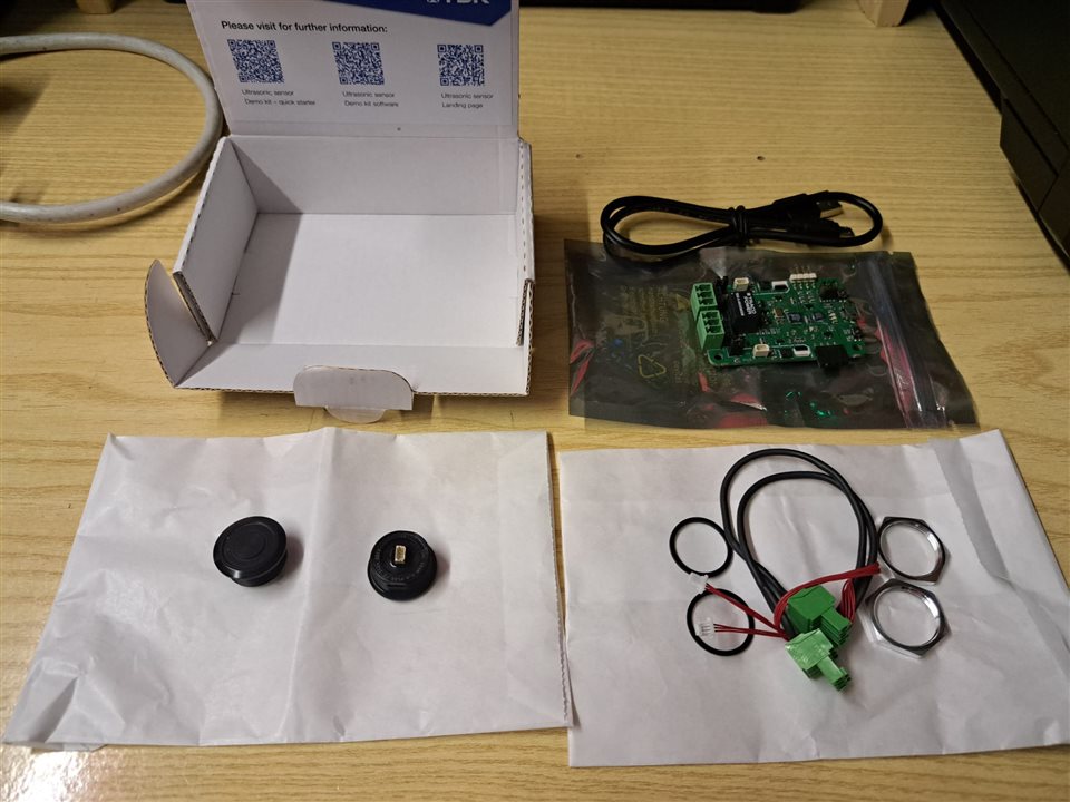
The Ultrasonic Module demo kit includes the following items:
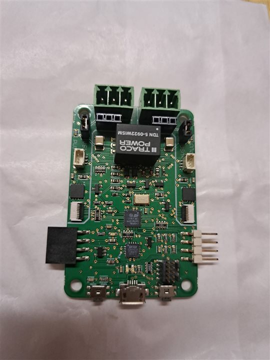
- An adapter board, which includes
- all the logic to provide power to the (up two) USSM sensors. All the power supplies are generated from the single 5V power supply from the USB connection. More specifically, the integrated step-up converters generate a voltage of 12 V
- An STM32 microcontroller, which runs the firmware that can program the USSM registers, can read the USSM output (echo signal) and the analog value that represents the continuous readings of the USSM signal. The latter feature is very useful in the development phase, when you need to understand how the environment affects the precision of the measure
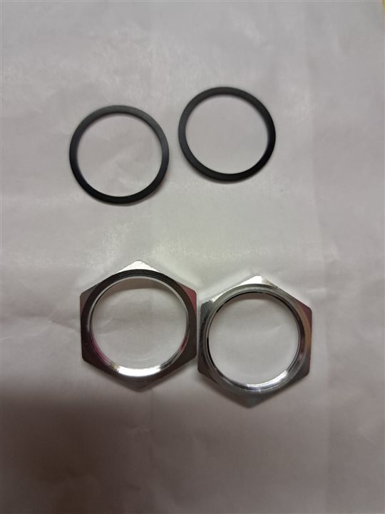
- Two Ultra Sonic Sensor Modules (USSM) 1.0 PLUS-FS, inclusing washers and gaskets for the installation
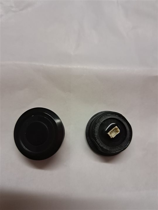
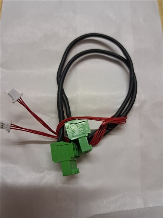
- Two cables to connect the sensors to the board. The connector on the USSM is a SWB 1002WVS-03E-LPSW
First test
Making the first test with the evaluation kit is absolutely straightforward:
- Connect the USSMs to the evaluation kit, using the adapter cables included in the box
- Connect the evaluation kit to the PC using the Micro-B to USB-A cable included in the box
- Download the GUI software from this link https://www.tdk-electronics.tdk.com/en/3126242/design-support/design-tools/ussm/tdk-demo-kit-software
- Unzip the content of the file and double-click the executable file (no setup is required)
- The GUI will automatically detect the evaluation kit and connect
- Select the command to send to the evaluation kit (more about available commands later in this post)
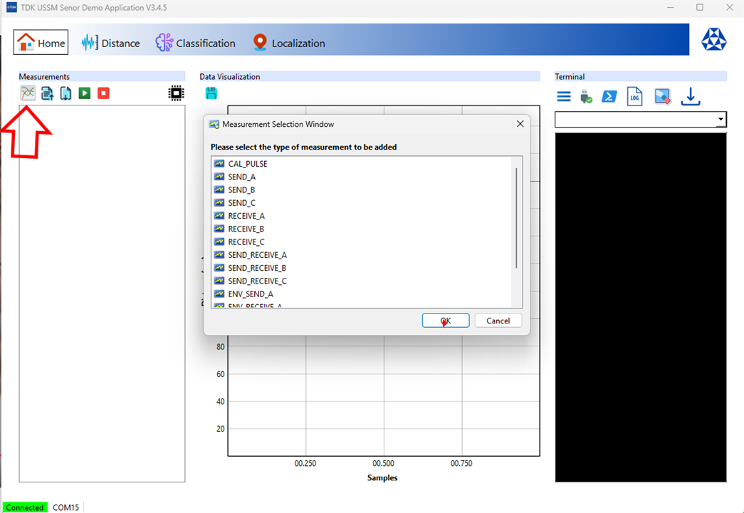
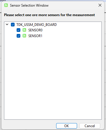
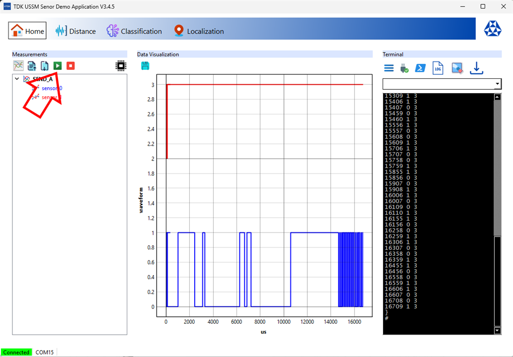
- Select the sensors
- Click the “Play” icon to send the command. Here is the output of the SEND_A command. The chart shows the behaviour of the IO data line (again, more about the format of the communication frame sent out by the sensor later in this post)
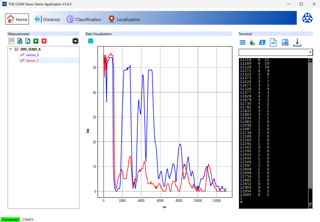
An interesting feature is the ENVELOPE command, that shows in the chart the amount of reflected energy detected by the sensor over time
The evaluation kit
There are plenty of information about the adapter board in the USSM demo reference manual [link].
The goal is to learn something from the schematics and from the software/firmware to have a solid background to build my device upon.
BTW: it’s a bit confusing to have parts of the schematic all over the document. It would have been nice to include the complete schematic for reference
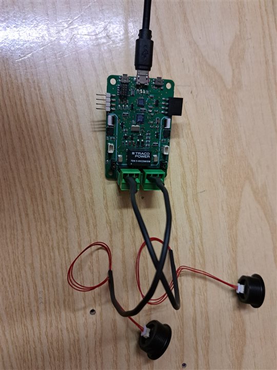
Power supply
According to the datasheet, USSM accepts a voltage from 8 to 18 volts. The evaluation kit is equipped with a DC-DC converter with dual output. This choice was due to the need to generate the 24 V required to program an external EEPROM, where some USSM modules parameters are saved and read back by the microcontroller firmware.
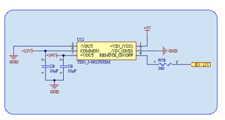
An industrial-grade isolated DC-DC converter is used in this case, which is quite overkill for my application. The component is made by Traco, part number is TDN 5-0922WISM
Since I don’t need to program an external EEPROM, a cheaper solution should be fine. I will probably use a step-up converter, but I may change this decision after some preliminary tests. I am a little bit confused by the size of the DC-DC converter: it can handle up to 5 watts, whereas the consumption of the sensors is about 60 mW each (5 mA at 12 V).
USSM communication
The USSM evaluation kit is based on an STM32 microcontroller, which implements a convenient interface between the host (typically a Windows PC) and the integrated circuit mounted inside the USSM. The IC has code E524.33 and it made by Elmos. This component can perform several filtering operations on the sound signal reflected by an obstacle. As a matter of fact, it features several registers that can be fine-tuned to filter out environmental noise and optimize distance measurement.
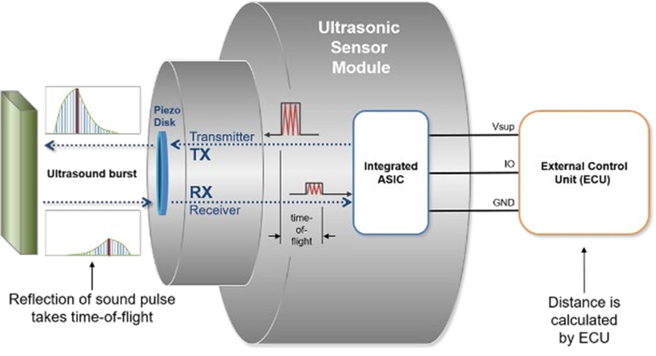
The E524.33 IC has one single data pin, which acts both as input and output. Data is sent back and forth the MCU and the E524.33 by pulling the single line DATA low for defined periods of time. For example, to send a very common command like SEND_A, the IO data line is pulled down for a time equal to Tsnd (100 us). This triggers a burst and the consequent time-of-flight measurement. In my opinion, the way the SEND_A command has been implemented is very smart. For a basic usage, you can use the SEND_A command, and see the USSM as a very simple ultrasonic ranging sensor with a trigger-echo interface. However, more advanced functions can be implemented by modulating the amount of time the IO data line is pulled down. For example, to send the SEND_B command is sent by pulling down the IO data line for Tmeas (200 us).
The most relevant commands supported by then E524.33 IC chip are
- SEND_x (where x can be A, B or C and identifies the measurement parameters profile). This command initiates a burst signal via the internal drivers followed by a measurement sequence and a status sequence. Internal logic generates a burst signal for the transducer first. Incoming reflected pulses are amplified, digitally filtered and compared to customer programmable threshold levels or to the automatically generated threshold. If the echo pulse exceeds the set threshold level, the IC triggers the IO line.
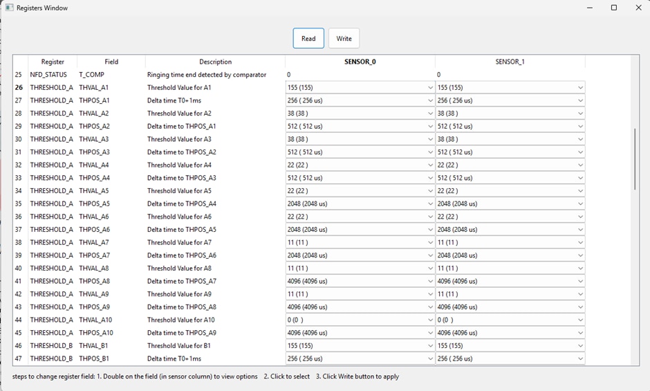
According to the E524.33 datasheet,The IC can store 3 individual profiles, called profile A, profile B and profile C, which are used by the 3 SEND commands and the 3 RECEIVE commands. In each profile the number of pulses (NPULSES), the length of measurement time (TMEAS) and a threshold curve selection (THSEL) can be stored in the volatile memory to configure the different profiles.
However, the provided GUI application shows a list of 10 couples of registers for each profile. Each couple of registers identifies a point of the threshold curve in terms of
• Delta time (in us) from previous point
• Received signal level, in a range from 0 to 155
The time elapsed from sending out a burst signal to receiving an echo signal from an object is proportional to the distance of the object. Once a cycle is initiated by the control unit, it cannot be interrupted during the programmable measurement time. If no measurement is performed the device is in Idle state.
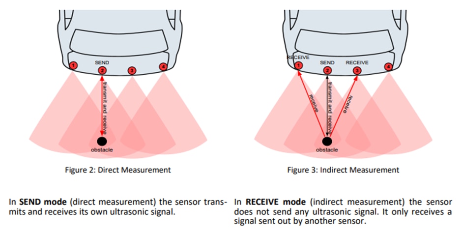
- RECEIVE_x . Initiates a measurement sequence without preceding burst, useful for triangulation in systems with multiple transducers. Image from the E524.33 IC datasheet shows the difference between the SEND and RECEIVE commands
- ENVELOPE_SEND_A: Initiates a burst signal via the internal drivers followed by a measurement sequence of profile A. Instead of the echo detection the envelope signal is shown on the IO line. The IO line conveys an analog value that corresponds to the amount of reflected energy detected by the sensors. Using the plot, it’s easier to fine-tune the threshold parameters
Here are a typical measurement cycle and the behaviour of the IO line
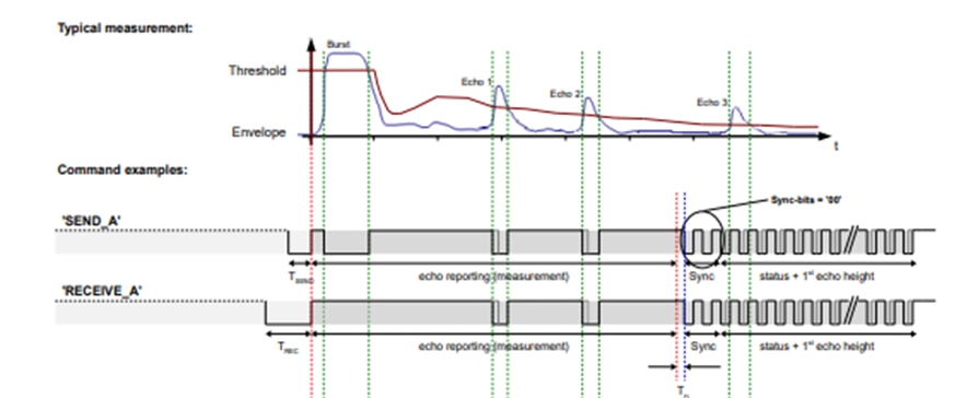

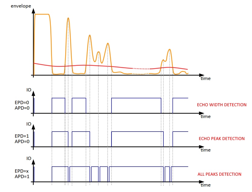
After the MCU drives down the IO data line for a time equal to Tsnd or Tmeas, the USSM starts driving the IO data line. In the case of SEND/RECEIVE commands, the IO data line is driven low every time time the reflected sound energy goes above the threshold. There are a few settings that can be changed to select how the threshold crossing is detected, namely
- Echo width detection: The IO-line is pulled down when the envelope signal crosses the threshold curve. The detected position of an obstacle depends on the ratio between the echo maximum and the crossing point of threshold curve with envelope signal.
- Echo peak detection (EPD): the IO-line is pulled down at the first maximum after the envelope signal crossed the threshold curve. The detected position of an obstacle nearly stays constant even with varied gain or threshold crossing.
- All-peak detection: detects all maxima when the envelope signal is above the threshold curve. Each detected maximum will pull the IO line to GND
Image below shows how the IO data line is driven depending on the selected method
MCU interface
After this overview of the communication interface of the USSM, the question is: which is the better way to integrate the sensors in my project?
The premise is that the minimum hardware requirements 1re
- some GPIOs or I2C or SPI bus to drive a local display
- support for wireless connectivity (Bluetooth or Wifi) to send and get data from a mobile application.
With these assumptions in mind, I can say that I can't use the evaluation kit as a development board, because it lacks the pins to interface with display and wireless module. Also, I could not find the source code of the firmware (only binaries are available). This means I can’t reuse the code that manage the sensors. So, instead of starting from scratch, a more viable option is to use an Arduino board and leverage the library available on the TDK website [link].
There are two other options now to choose from.
Interface the evaluation kit with the Arduino board
I could connect my Arduino board to the evaluation kit.
According to the documentation, the preferred solution to communicate with the evaluation kit is through the LIN interface, which requires, from my side, at least a LIN transceiver.
Another option could be the use the SYNC connector, which features an I2C interface. Since source code of the firmware of the evaluation kit is not available, I can only guess, based on the limited information included in the evaluation kit user guide, that this connector can only be used to forward commands to other boards by means of the SYNC_READ command.
As a final alternative, I could use the mini-USB port, but this would force the use of a board with a USB host interface.
Interface the Arduino board with the USSM
The other option is to connect the Arduino board to the USSM using the IO data line. The datasheet suggests two possible solutions
- Open-drain driver. This solution uses a digital output to drive a MOSFET, which acts as an open-drain driver to drive the USSM's IO data line down.
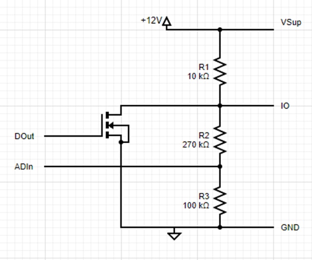
When DOut is ON, the MOSFET pulls the IO node to 0 V. When DOut is OFF, the MOSFET is high-impedance, so IO is pulled up to +12 V through R1.
ADIn, on the other hand, can be used to read the IO-line status (digital or analog) mainly in receive mode. But it also can be read at any time to check IO-line status.
Advantages
Works for all MCUs (IO voltage levels) with properly calculated voltage divider resistors to satisfy Vddmcu = Vsup * R2/(R1+R2).
Supports analog signal over IO line and can use ENVELOPE commands.
Limitations
Requires 2 IOs on MCU side per sensor (1 digital out + 1 analog/digital in).
The command has inverted polarity (MCU 1 drives 0 on sensor IO and MCU 0 drive 1 on the sensor IO).
Works only for single sensors VSup (USSM supply voltage) with small variation (+/- 20%).
- Bidirection level shifter: the second solution is to use a bidirectional level shifter. The working principle is that LOW is propagated from one side to the other, while HIGHs are established independently via pull-ups.
- If
IOtries to rise aboveVDD + Vth(threshold voltage, ~1–2 V), the MOSFET conducts and clamps the voltage, enabling level shifting. - If either side pulls low (to GND), the MOSFET conducts and propagates the LOW across both sides.
-
If neither side pulls low, then DIO is pulled high by R2 (and stays at VDD) and IO is pulled high by R1 (and stays at VSup)
- If
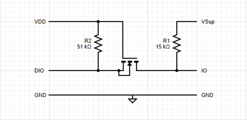
Advantages
Only 1 IO on MCU side is needed to drive one sensor.
Setup works independent of the sensor-side power-supply voltage level (7 to 18 V).
Direct drive (no polarity changes of the signal).
Limitations
This solution works only for digital commands which means that ENVELOPE commands will not work properly with such a setup.
It might also not work if the MCU GPIO characteristic VIL (V Input Low) is not satisfied.
Conclusion
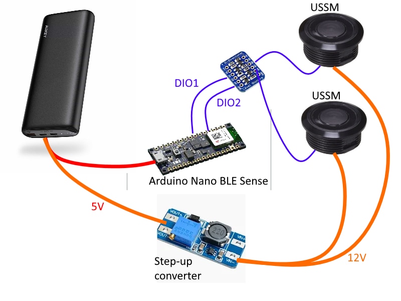
After evaluating the available options, I decided to proceed in this way.
- The device will be powered by a standard powerbank with a 5V output. The powerbank will power the Arduino board
- A step-up converter will be connected to the powerbank to generate the 12V required by USSM
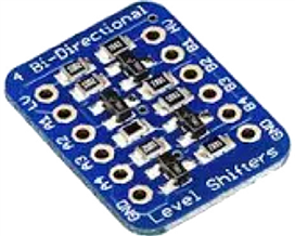
- Since the USSM is pointed upwards, I don’t expect any particular noise issues. For this reason, and for the sake of simplicity, I will use this breakout board from Adafruit as level shifter
The diagram below shows the boards that will made up the first version of the SwishMaster device
References
USSM datasheet
Evaluation kit datasheet
USSM GUI
E542.33 datasheet
Arduino library
https://www.tdk-electronics.tdk.com/en/3105452/design-support/design-tools/ussm/ussm-arduino-library


