


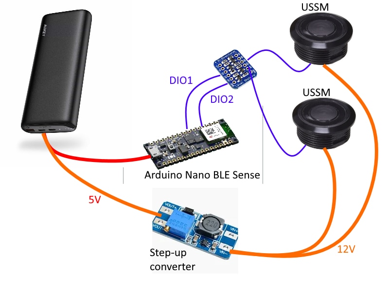
As I said in my previous post, the SwishMaster device will be based on an Arduino 33 BLE Sense, which connects to two USSMs by means of level shifters. The overall hardware architecture is shown in the following picture
However, after checking parts availability in my components shelf, I switched the an Arduino Nano 33 IoT
Connecting the USSM
As shown in the diagram above, I am going to use a level shifter to connect the USSM IO data line to the Arduino board. In particular, I chose a bidirectional level shifter converter made by Adafruit, which is made by four identical channels. Each channel features the following circuit
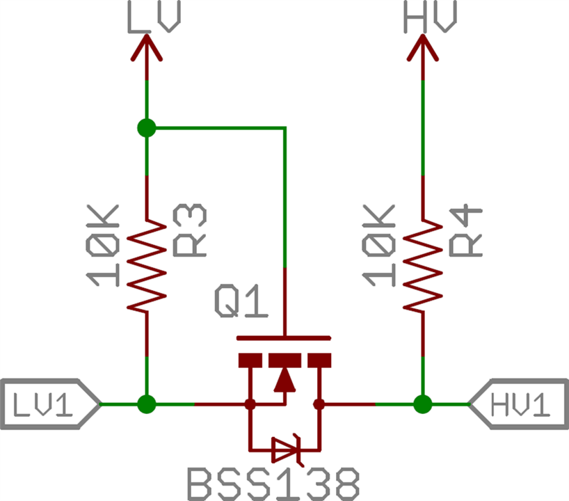
Here LV (low-voltage) side is connected to a IO on the Arduino board, and the HV (high voltage) side is connect to the USSM IO data line. Regarding the MOSFET pins,
- the gate (G) is tied to the LV power supply (in my case, 3.3V)
- the source (S) is connected to the Arduino IO pin
- the drain (D) is connected to the USSM IO data line
The principle of operation for thsi circuit is
- when both sides (LV1 and HV1) are high, the voltage on the source is equal to the voltage on the gate, and the MOSFET is not conducting. Hence, HV1 is pulled-up to the voltage of the HV power supply
- when LV1 is pulled-down, the MOSFET furms on because the voltage between gate and source is 3.3 V. The drain is pulled-down as well, so the low state is propagated to HV1
- when HV1 is pulled-down, the MOSFET’s body diode (intrinsic diode between drain and source) conducts slightly, pulling the source (LV side) a little below 0.7 V. This drop causes the MOSFET to turn on, and the low state is propagated to LV1
According to Adafruit documentation, the maximum voltage on the HV side is 10V. This statement puzzles me, because the BSS138 states that the maximum drain-source voltage is 50 V. Anyway, just to be on the safe side, I will power the USSM with 10V, since such a voltage is still within the specifications.
Another problem with the breakout board is the 10K pullup resistor (or, at least, this is my explanation). This resistor is bit too strong and prevents the signal to get close to the ground when the sensor imposes a low state on the data line. This condition is shown in the following screenshots of the signals captured by the oscilloscope (red signal is the signal on the LV side, yellow is the signal on the HV side)
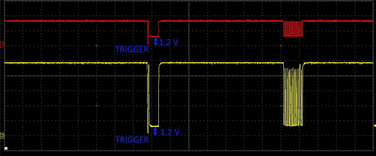
The signal from USSM is read correctly by Arduino, but, in my opinion, the voltage of the low state is too close to the threshold between low and high states. As a matter of fact, according to the Microchip SAMD21G18 datasheet, a low state is detected when voltage is below 0.99 V...
The simplest solution is to remove or short-circuit the pull-up resistor on the breakout board and add an external pull-up resistor of maybe 15K or more. At the moment, I will keep on working without any changes because I fear damaging the board. I will make this change after I have a working prototype
Reading USSM data
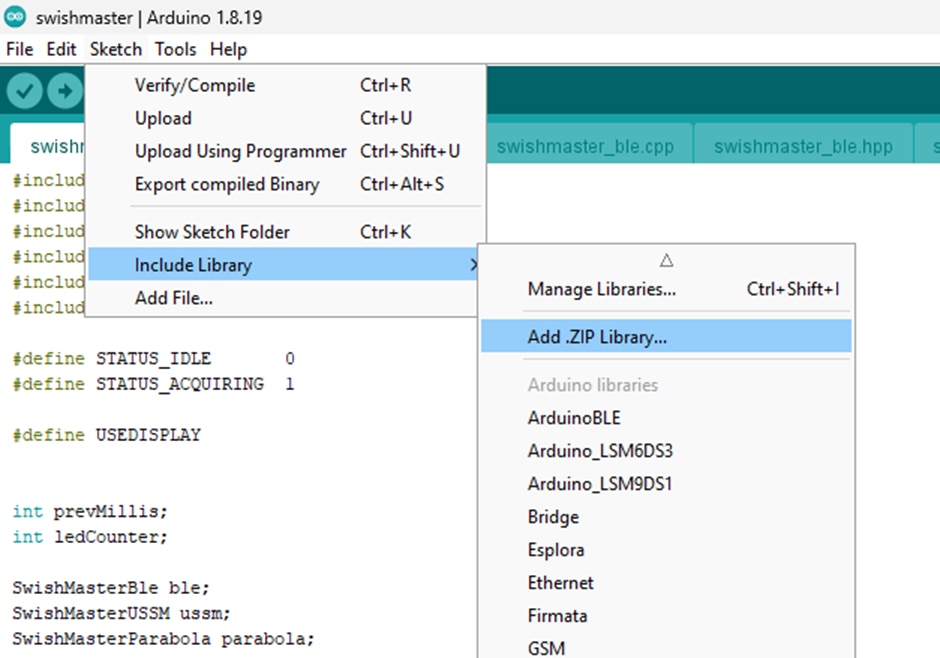
To interface with the USSM, I will leverage the Arduino library provided by TDK and can be downloaded from this link.
You can install the library from the Arduino IDE by clicking Sketch -> Include library -> Add .ZIP library
Here is an example of usage of the library. In my case, I just need to measure distance in centimeter. The example TDK_USSM_multiple_cm implements exactly what I need for this project
#include <TDK_USSM.h>


//-- Sensors Pinmap Sensors
#define N_SENSORS 2
const int IoPins[N_SENSORS] = {14, 16}; // Trigger/Echo Pin of Ultrasonic Sensor

// Note: Echo Pins could be same as Trigger pin if a bidir level shifter is used.

TDK_USSM TdkUssm(IoPins, N_SENSORS); //Initialize Sensor Pins

//-- Setup
void setup()
{
  Serial.begin(115200);
}

//-- Runtime.
void loop()
{
 while(1)
 {
   for(int i=0; i<N_SENSORS; i++)
   {
     Serial.print( TdkUssm.GetDistanceCm(i) ); // Prints Distance in cm of sensor i.
     Serial.print(" ");
     delay(100);
   }

   Serial.println(); // Terminate single capture line
   delay(2);
 }
}
I just changed N_SENSORS (from 4 to 2) and IoPins to match the pins used on my board.
The original version of the library did not compile, so I had to make a little change to the file Arduino/Libraries/TDK_USSM_Ultrasonic_Sensor-1.0.2/src/tdk_ussm_defs.h
The change is shown in the following code snippet
/*! \ingroup tdk_ussm
 * \brief Measurement Data Structure.
 */
typedef struct
{
    uint16_t id; // <-- original code was uint8_t id
    uint8_t lsb;
    uint8_t nbit;
    uint32_t val;
    const char *name;
    const char *description;
    const eLUTStruct *lut;
} eParameterElement;
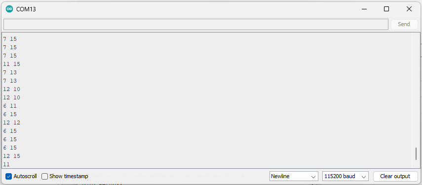
First test
And here is the terminal output after the above test code have been downloaded and run
Next steps
I am going now to implement the firmware to calculate the ball parabola, show results on a local LCD screen, send data out through BLE and so on and so on.
