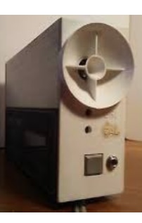
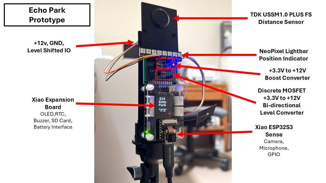
Hardware Description
Features
- Ultrasonic Sensor measures vehicle position from 225cm to 50cm
- Visual indication of position in 25cm steps
- Audible and Visual feedback when position is less than 50cm
- Onboard display of measured distance
- Vehicle identification using License Plate Recognition (LPR)
- MQTT notification of vehicle parked
Block Diagram
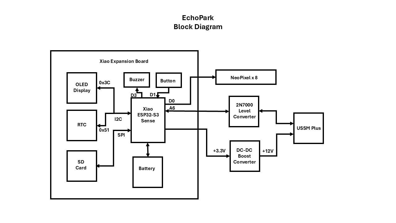
Components
Module BOM
| Component | Description | Qty | Link |
| TDK USSM1.0 PLUS-FS | ULTRASONIC SENSOR, 74.5KHZ | 1 | www.newark.com/.../82AK9947 |
| Xiao ESP32S3 Sense | Xiao ESP32S3 with OV2640 Camera | 1 | www.seeedstudio.com/Seeed-Studio-XIAO-ESP32S3-Sense-Pre-Soldered-p-6335.html |
| Xiao Expansion Board | Xiao Expansion Board with 0.96 OLED | 1 | www.seeedstudio.com/Seeeduino-XIAO-Expansion-board-p-4746.html |
| DC-DC Boost Converter | 3.3V to 12V Boost Converter | 1 | www.amazon.com/.../B08M19C7MM |
| 2N7000 MOSFET | N-Channel MOSFET 200mA 60V | 1 | |
| DC 5V Active Buzzer | Electromagnetic Buzzer 2300Hz 85dB @10cm | 1 | |
| Carbon Film Resistors | Various values 5% 1/4W | 3 | |
| NeoPixel Stick | 8 x 5050 RGB LED with Integrated Drivers | 1 | www.adafruit.com/.../1426 |
| JST SH 1.0mm pigtail | 3 Pin Male Connector with 20AWG 20cm wires | 1 |
I will defer the detailed hardware description to the final project blog post but will show the operation of the prototype assembly that I am testing.
Initial tests
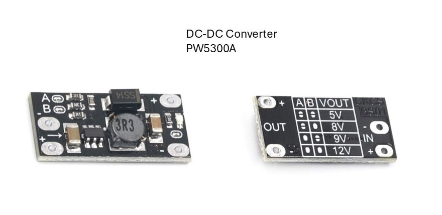
Boost converter
The first component that I checked out was the DC-DC Converter. I didn’t expect any issues because it is using the PW5300A part which has far more capability than is required for this simple circuit and it is switching at a fixed frequency of 1.2MHz.
The input to the converter is the output of the 3.3V regulator on the Xiao ESP32S3. The documentation states that you can draw 700mA from the regulator, but I’ll need to be wary of too much WiFi activity. I want to use the 3.3V because I’d like to have the ability to run off a battery if I want to use this project in a portable mode.
The output of the converter by default is 12V but is selectable to 5V, 8V, or 9V using pad jumpers. I decided to leave it at 12V to match the setup on the Demo board. The USSM is capable of running down to 8V but it is easier to correlate when setups are the same.
The output was at 11.98V with reasonable output ripple. I will document this in the final blog.
Level converter
Since I only have to translate a single IO pin for the sensor I decided to use a discrete MOSFET circuit rather than use a 4 channel BSS138 level converter that I have from Adafruit. It will also make it easier to make changes to the pullup resistors in case that is necessary.
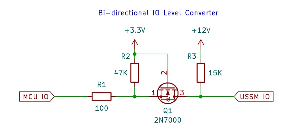
My primary concern with this circuit is that I am using a relatively old N-channel FET so the on resistance and VGS threshold are higher than more recent parts. The typical values for this part should be fine for this circuit but if I get a part that is on the high side of the specification it could be marginal. E.G. the typical VGS is 2V but max is 3V. The currents are under 1mA for this setup so that helps. I tested the converter statically and everything looked good (under 10mV). I also observed it on a scope and it was switching cleanly but I may reduce the 15K pullup on the USSM side to get better transitions (when I copied the circuit from the reference manual I did not account for the extra 10K pullup in the cable – that was pointed out by another challenger). I am doing the testing using my handheld scope and I haven’t set up the USB interface to my PC yet so some of this documentation is being deferred until the project blog.
Prototype Assembly
Distance visual feedback
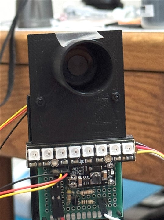
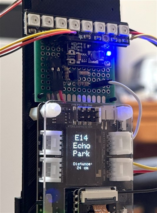
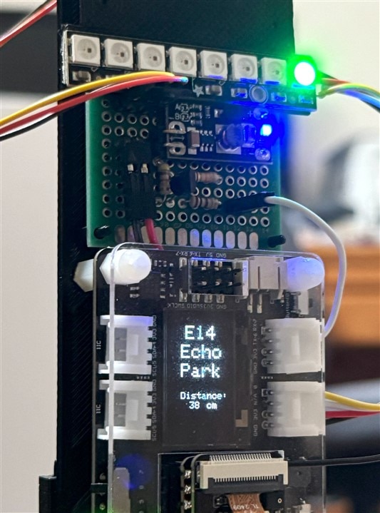
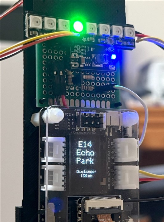
Dave Beacon had mentioned in a comment on an earlier post that I could use an LED pixel strip as a horizontal light bar that illuminated more pixels as you got closer then flashed solid red once you reached zero distance. It turns out that I had an Adafruit 8 NeoPixel strip available so the following is my first implementation attempt. I am just lighting a single pixel that moves across the strip based on distance, but I may change that later. My initial testing was in my office, so my “zero” distance was 25cm and 25cm steps from right to left as distance increases.
The following pictures show the progression of the pixel lighting based on the distance that is displayed on the OLED screen.
I haven’t implemented blinking all the LEDs red at the “zero’ distance, but I will do that later in addition to adding an audible alarm using the buzzer.
One thing that I had forgotten about is how bright these NeoPixels are. It’s recommended that you run them off a 5V supply, but I usually connect them to a Grove interface, so I run them on 3.3V. I had left the intensity at 100% and when testing I had one light up when I was looking directly at it, and I had flashes in my vision for about 10 minutes. I’ve reduced the brightness to 30% while testing.
Zero distance audible alarm
There is a passive buzzer on the Xiao Expansion board down next to the MCU. I was going to use this as alarm when the correct parking distance was reached. When I tried the test program I didn’t hear anything. It turns out that I had cut the jumper trace to the buzzer so that I could use that GPIO pin elsewhere. I restored the connection, and the buzzer was audible but not very loud. This is a passive buzzer driven with a PWM pattern on the GPIO pin. I then recalled that I have never had any luck with these passive buzzers. I had probably cut that trace earlier because it was a waste of a GPIO pin…
I also recalled that I had purchased a bag full of active buzzers to address this problem. These are relatively small (12mm diameter x 10mm tall) and even though they are rated at 4-6V, they work well at 3.3V.
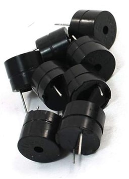
So, I added some jumper wires to the GPIO and ground, mounted it near the level converter, and proceeded to test it out. The sound level was good, but I’ll have to see whether it can be heard in the vehicle (might be difficult with the windows up and the engine running). I then encountered something that I hadn’t considered – my distance measurements were all messed up. The resonant frequency of the buzzer is 2300Hz, but that all must have been reflected at the sensor because of where I had mounted it. I repositioned the buzzer behind the assembly and pointed upward and that corrected the problem. I am going to mount the LED strip and buzzer separately from the sensor assembly in the final version, so hopefully this shouldn't be a problem.
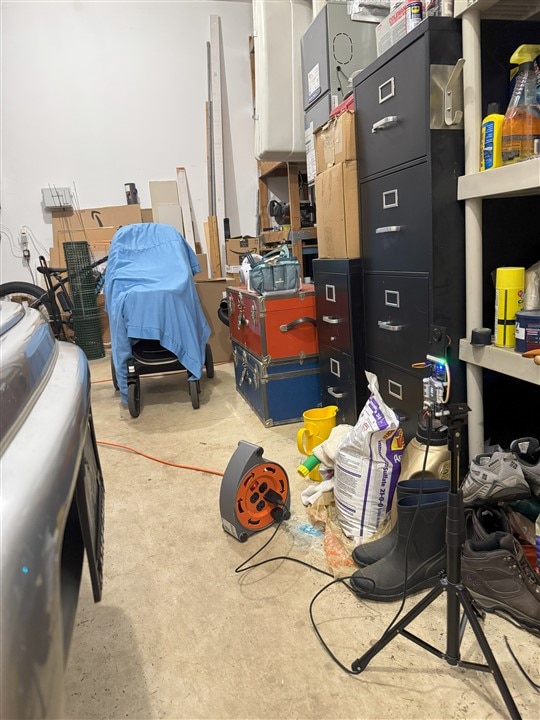
Testing in the garage
Time to do some testing in the garage. I have changed the "zero" distance to 50cm. For the first test I positioned the sensor assembly at the garage door and just walked toward it. I couldn’t find a small “vehicle” handy that I could attach the cell phone to, so apologies for the shaky video.
Echo Park Distance Test
Then I did a quick test with the sensor pointed at the front of the car. I was somewhat surprised that the sensor actually alarmed at 50cm and stopped at 53cm. Of course, this was not a dynamic test and I’m realizing that it might be a real challenge trying out to figure out how to document that. Maybe if I had a dashcam...
Parking Distance 50cm
At 53cm the first pixel lights and the alarm stops.
I am having concerns about how responsive this system needs to be. I have a median filter to try to de-glitch the measurements and a moving average filter following it. I’ve had to back those off a lot to get a reasonable tracking response. I guess a lot of empirical testing will be required.
License Plate Recognition
I haven’t quite got this working yet. I plan to use a cloud service to do the number/character extraction. I’ve seen several project examples using this method. My first attempt has been experiencing memory issues, and I’ve been getting into reboot loops a lot.
I have a couple of more things to try and I’m still hopeful that I can get this working. That will be the subject of the next post.