


In this post, I am going to share my progress on building the container and assembling the electronic components of the SwishMaster device
The case
The SwishMaster case is made up of three main parts
1. The main case
The main case has slots for all the electronics components, namely
- 2 USSMs
- The Arduino Nano 33 IoT board
- The stepup converter
- The level shifter
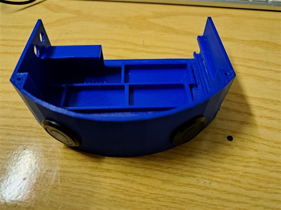
Each component will be housed in the position shown in the following picture
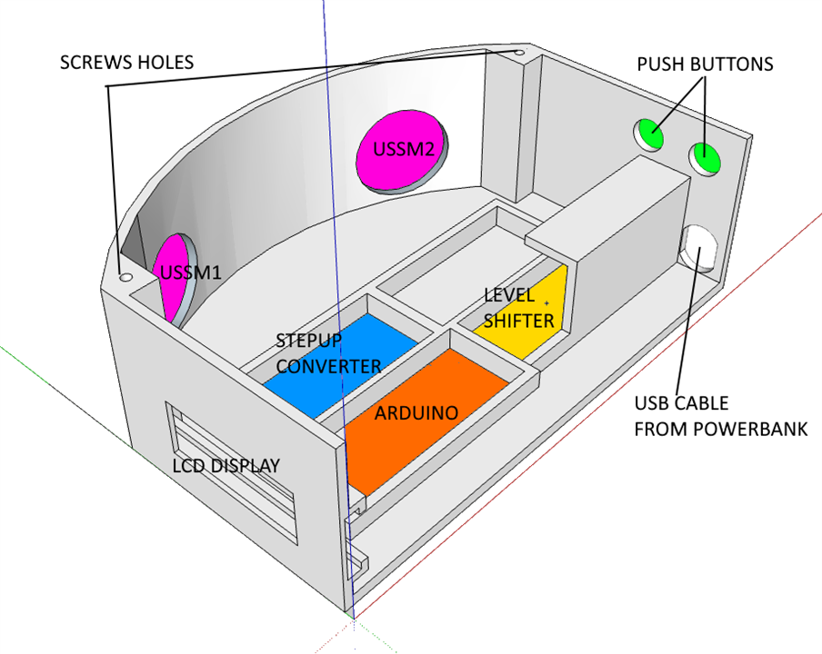
Note that the holes for the USSMs are 50 degrees apart, to match my findings on the area covered by the USSMs themselves (see my post here)
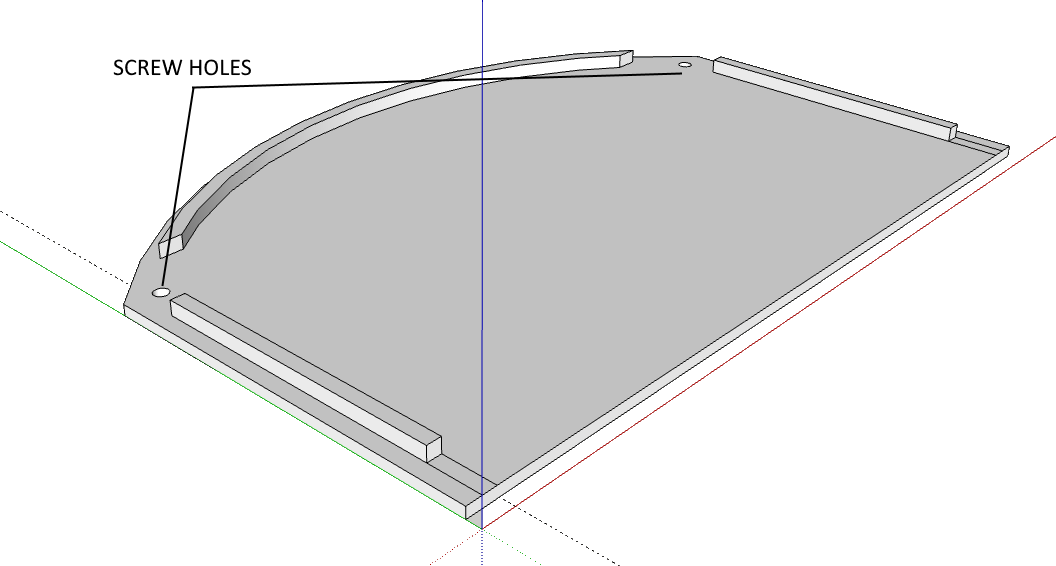
2. The cover
The cover is quite simple. It stays in place thanks to a bevel and is secured to the case with two screws
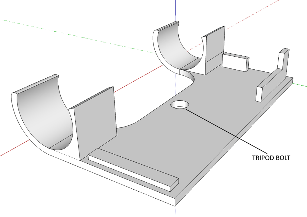
3. The base
The base has two brackets to hold the power bank and features a bolt to fix the SwishMaster to a camera tripod
Installation
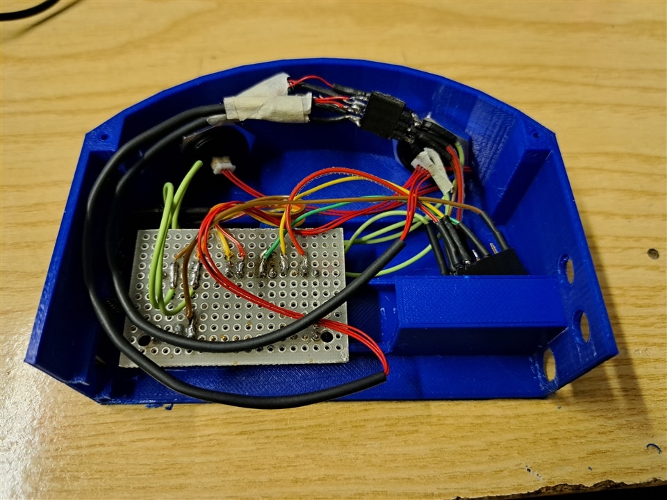
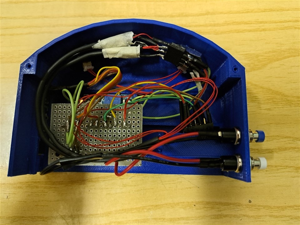
The following pictures show the installation process of the electronic components that make up the SwishMaster
1. USSMs
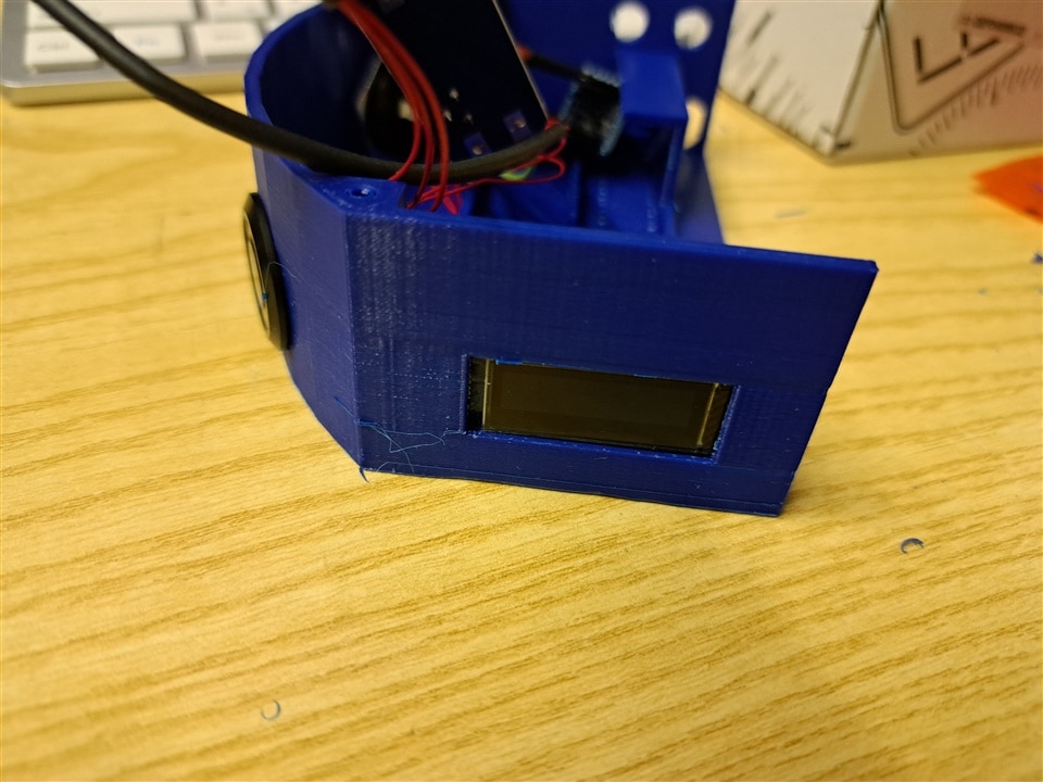
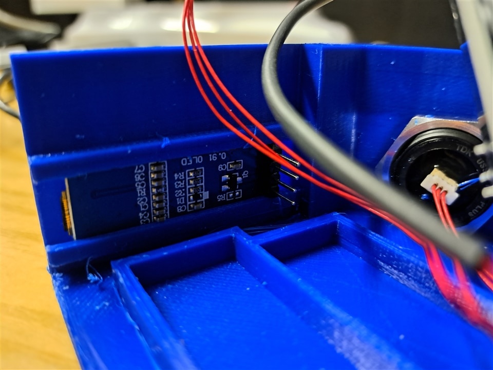
2. LCD display
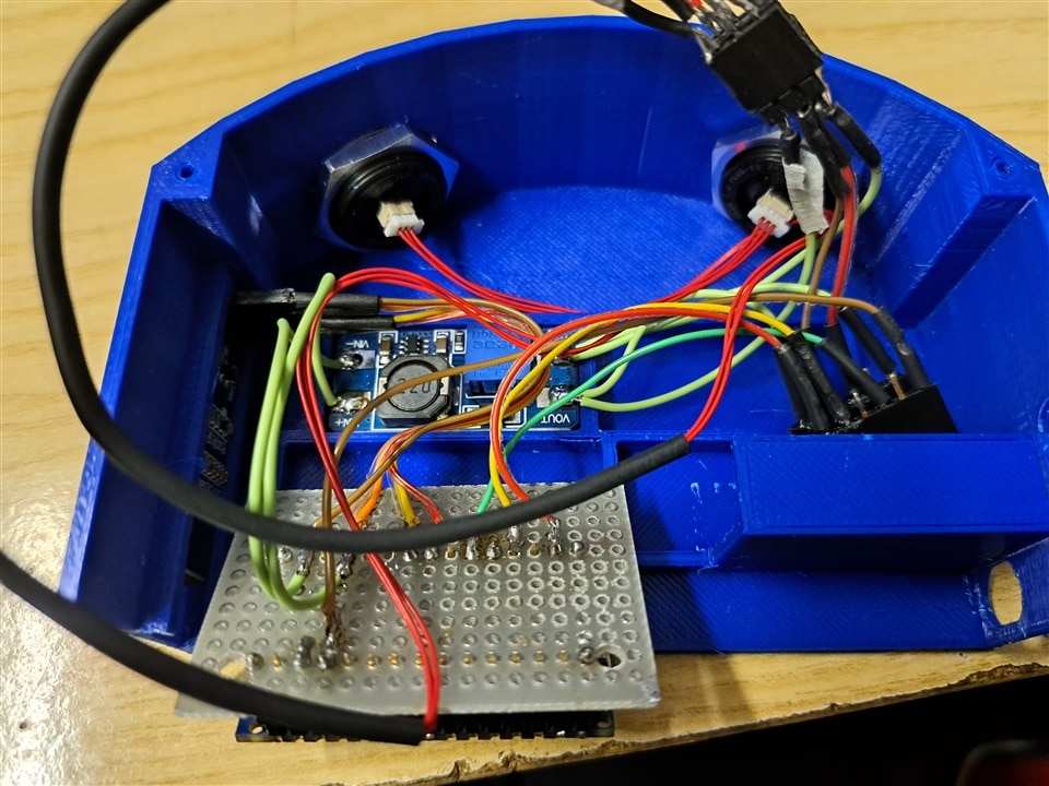
3. Electronic boards
All the boards are kept in place by the bevels (the boards fits exactly in the slots). For a better hold, I added some double-sided tape.
I also created a piggy-back for the Arduino board to simplify the soldering of the connections.
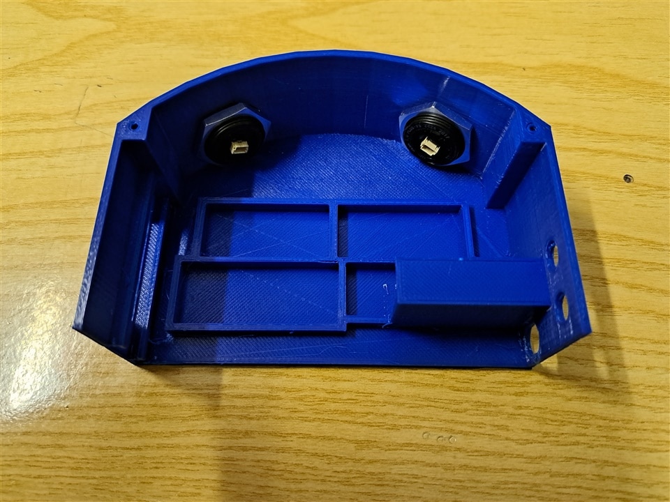
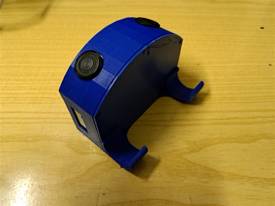
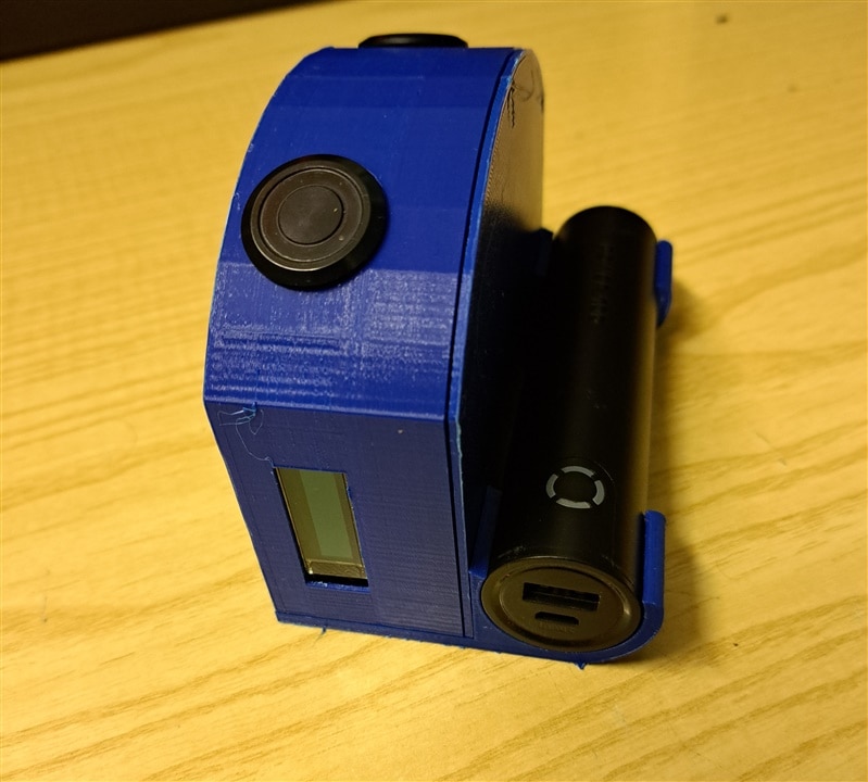
The final result
And, finally, here are some pictures of the first (almost) completed SwishMaster prototype
Next steps
Hardware assembly is 90% completed: some finishing are missing here and there. Firmware has been partially debugged: LCD display works as expected and trajectory calculation algorithm has been tested with simulated data. Now it's time to mount the device on a camera tripod and make some tests on field

