Power management is one of the challenging parts of a project. My device will be independent, battery-powered, as it will be placed on the rooftop tank; utility supply may not always be available. The device will be powered from a 18650 li-ion battery. The nominal voltage of a Li-ion battery is 3.7, which is not appropriate for an ESP8266 MCU board. I need to boost it to 5V or down it to 3.3V. Besides, I need a charging mechanism for the battery. I decided to use a Monocrystalline Solar Panel (5V, 1A) from DFRobot.
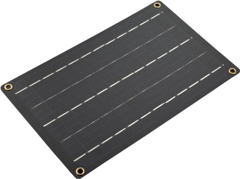
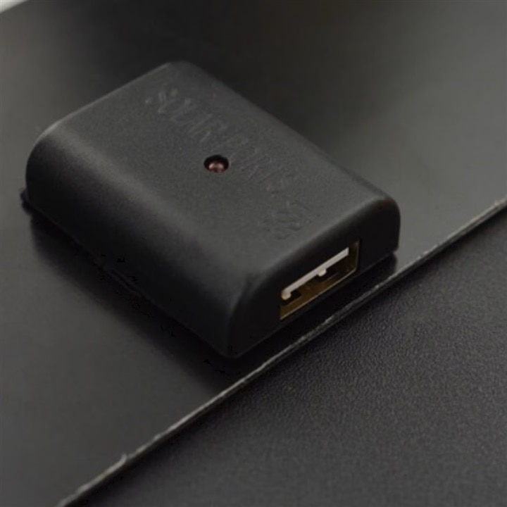
The panel has an internal regulator and provides a constant 5V to the output through the USB port.
A Li-ion battery requires a sensitive charging mechanism, and we can not directly connect a battery to a 5V supply. So, I manage the following UPS circuit for the battery, which takes 5V and charges the li-ion battery and also provides 5V constant output.
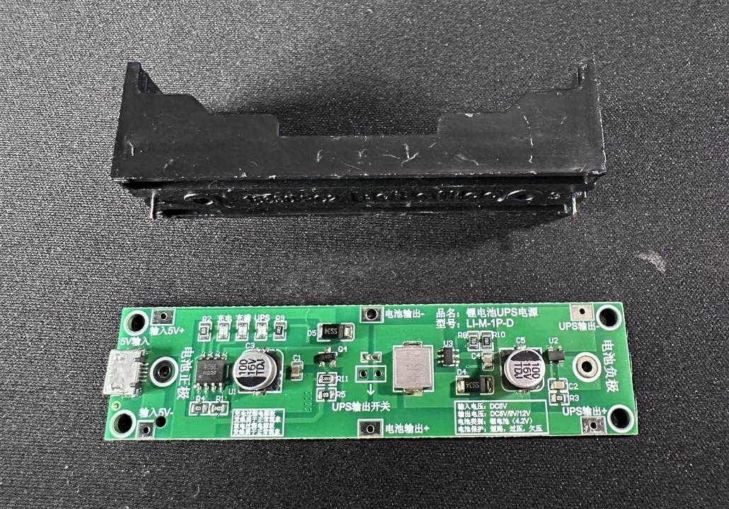
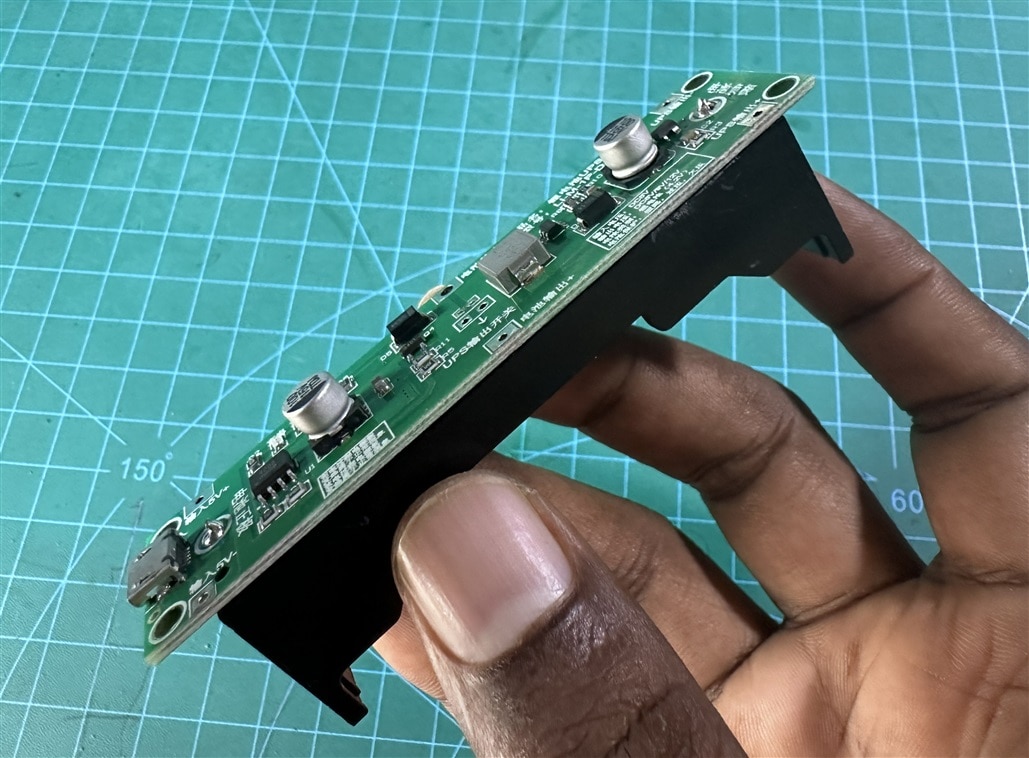
The circuit came with a separate battery holder. So, I soldered the battery holder with the circuit.
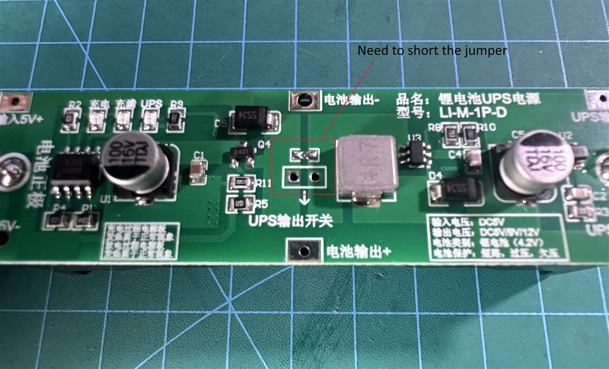
The circuit has a jumper that must be shorted to enable the output.
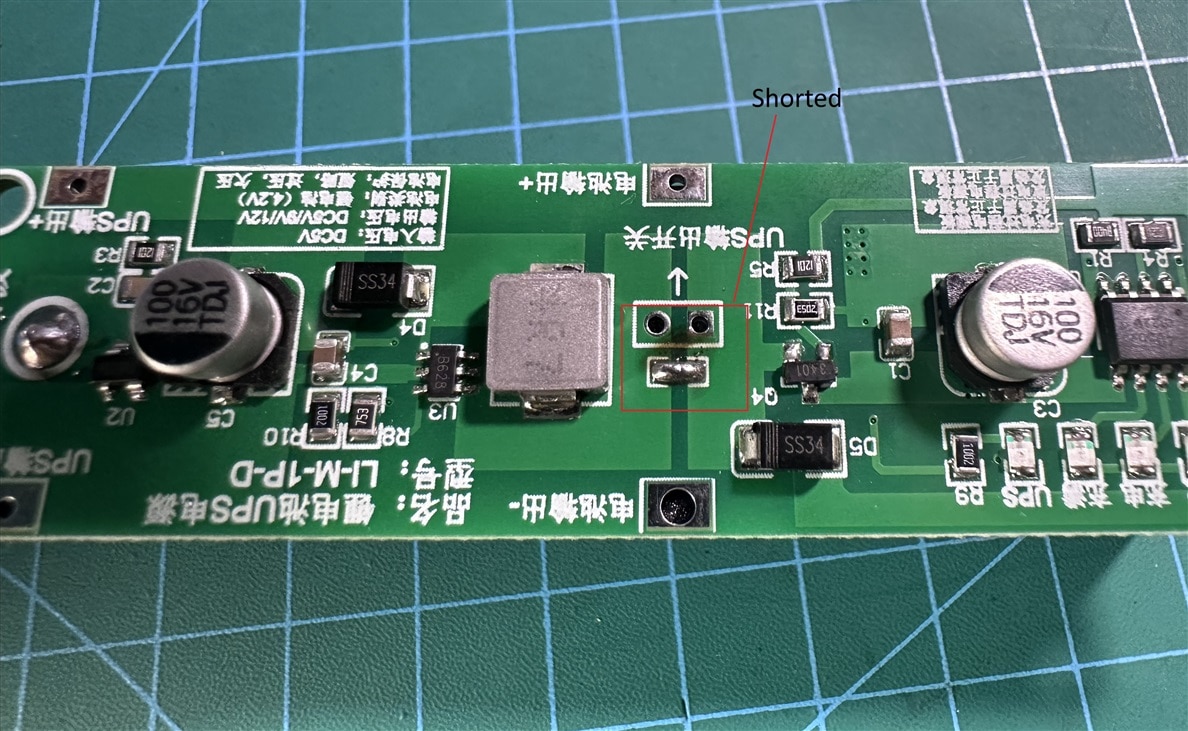
So, I added some solder and shorted the jumper to enable the 5V output.
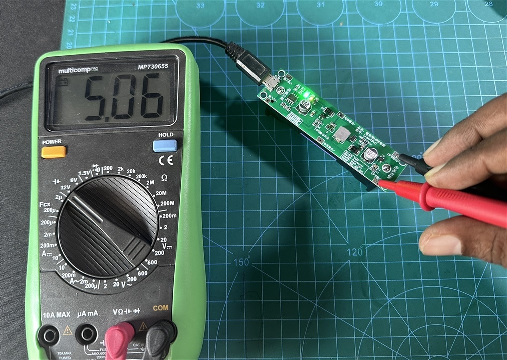
The 5V output is shown in the following image. This output will be provided to the Wemos D1 Mini board.
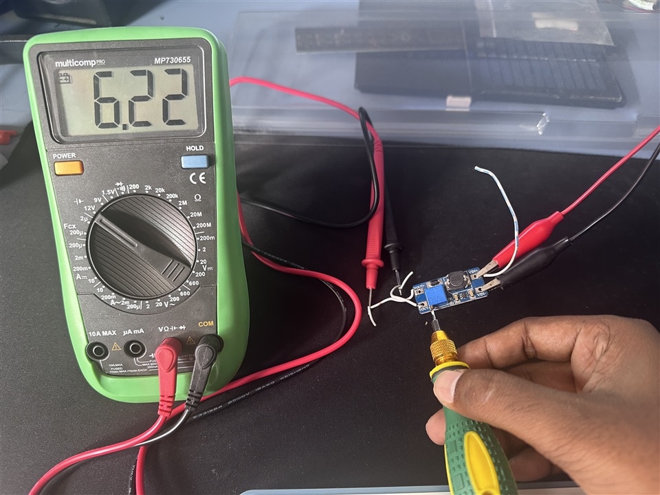
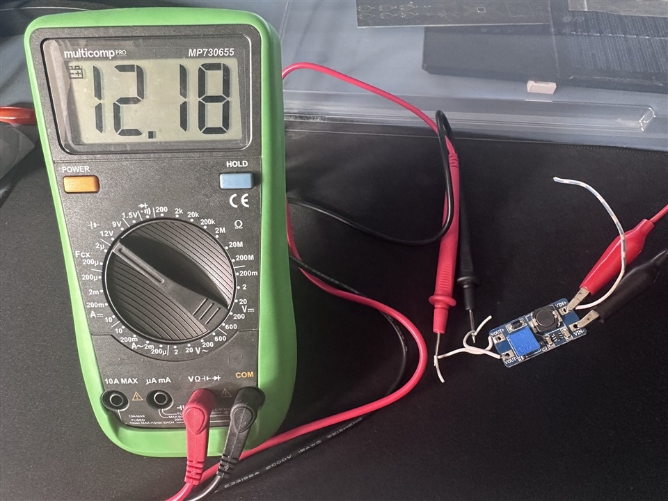
The sensor required 8 to 18 V to its Vsup pin. I decided to provide 12V to this pin. So, I collected an MT3608 adjustable boost converter module and adjusted the output to 12V for 5V input.
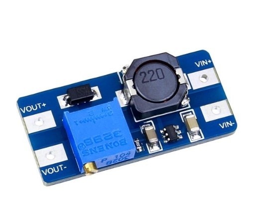
I connected the power supply output to the input of the boost converter module and attached the multimeter to its output. Then I gradually adjusted the trim pot until the module’s output reached 12V.