Previous posts for this project:
- [AirCare] InTheAir - Project Description
- [AirCare] InTheAir - Week 1: Getting a Launchpad to Blink
- [AirCare] InTheAir - Week 2: Preparing the Beaglebone Black
Introduction
I am away from home this week, attending Electronica. That doesn't mean I haven't prepared any content for this week's post though 
One of the goals for this project is to have the sensors combined with some kind of energy harvesting solution, much like the EnOcean sensors. To do this, I looked at combining the sensors and the CC3200 Launchpad with a battery pack and solar charging circuit. To test the idea, I started with some off the shelf components.
The parts used are:
- Solar panel 4V 0.8WSolar panel 4V 0.8W
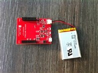
- Fuel Tank BoosterPackFuel Tank BoosterPack
- A micro USB cable
Solar Charging
There are some interesting posts and discussions regarding the Fuel Tank and solar charging:
- The specified item was not found.
- Eternal Power: Keeping the CC3200 Juiced by mraureliusr
- http://www.ti.com/lit/ds/symlink/bq24210.pdf
According to the datasheet, the bq24210 "... is suitable for charging from alternative power sources such as solar panel ...".
I took a small solar panel for testing, cut the micro USB cable and soldered it directly to the panel.
Alternatively, I could've used the "charge in" and "gnd" points foreseen on the board.
I put the whole thing in the sun, and the "charging" LED was lighting up!
There will obviously be need for actual measurements, but for now, this is sufficient to demonstrate the idea.
Power Save Mode
Thanks to Robert Peter Oakes' great videos on the Fuel Tank and how he repaired a suicidal boost regulator, I discovered his easy modification to enable low power mode.
I thought I'd give it a try myself, because like he says in the video, it's "something anybody who's got mediocre skills with a soldering iron could do"
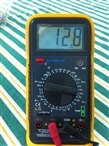
First I measured the current without the modification to confirm I had similar readings as he did. I had a reading of about 12.8mA, compared to his 13.4mA, so that was close enough.
Then, I took some female headers and bent the pins, so I could easily solder them onto the pads. The soldering went well, and the result is rather clean.
Finally, I made some jumpers, connected them and measured the current draw again.
Wow, what a difference: from 12.8mA down to 0.93mA! And this modification only took a couple of minutes to apply.
Next week, I hope to hook this up to the CC3200 and visualise the battery's charge over time.
This should help me see the effect of the solar panel charging during the day and the battery discharging over night.


Top Comments
-

dwinhold
-
Cancel
-
Vote Up
+2
Vote Down
-
-
Sign in to reply
-
More
-
Cancel
Comment-

dwinhold
-
Cancel
-
Vote Up
+2
Vote Down
-
-
Sign in to reply
-
More
-
Cancel
Children