element14 Community
element14 Community
    Register Log In
  • Site
  • Search
  • Log In Register
  • About Us
  • Community Hub
    Community Hub
    • What's New on element14
    • Feedback and Support
    • Benefits of Membership
    • Personal Blogs
    • Members Area
    • Achievement Levels
  • Learn
    Learn
    • Ask an Expert
    • eBooks
    • element14 presents
    • Learning Center
    • Tech Spotlight
    • STEM Academy
    • Webinars, Training and Events
    • Learning Groups
  • Technologies
    Technologies
    • 3D Printing
    • FPGA
    • Industrial Automation
    • Internet of Things
    • Power & Energy
    • Sensors
    • Technology Groups
  • Challenges & Projects
    Challenges & Projects
    • Design Challenges
    • element14 presents Projects
    • Project14
    • Arduino Projects
    • Raspberry Pi Projects
    • Project Groups
  • Products
    Products
    • Arduino
    • Avnet Boards Community
    • Dev Tools
    • Manufacturers
    • Multicomp Pro
    • Product Groups
    • Raspberry Pi
    • RoadTests & Reviews
  • Store
    Store
    • Visit Your Store
    • Choose another store...
      • Europe
      •  Austria (German)
      •  Belgium (Dutch, French)
      •  Bulgaria (Bulgarian)
      •  Czech Republic (Czech)
      •  Denmark (Danish)
      •  Estonia (Estonian)
      •  Finland (Finnish)
      •  France (French)
      •  Germany (German)
      •  Hungary (Hungarian)
      •  Ireland
      •  Israel
      •  Italy (Italian)
      •  Latvia (Latvian)
      •  
      •  Lithuania (Lithuanian)
      •  Netherlands (Dutch)
      •  Norway (Norwegian)
      •  Poland (Polish)
      •  Portugal (Portuguese)
      •  Romania (Romanian)
      •  Russia (Russian)
      •  Slovakia (Slovak)
      •  Slovenia (Slovenian)
      •  Spain (Spanish)
      •  Sweden (Swedish)
      •  Switzerland(German, French)
      •  Turkey (Turkish)
      •  United Kingdom
      • Asia Pacific
      •  Australia
      •  China
      •  Hong Kong
      •  India
      •  Korea (Korean)
      •  Malaysia
      •  New Zealand
      •  Philippines
      •  Singapore
      •  Taiwan
      •  Thailand (Thai)
      • Americas
      •  Brazil (Portuguese)
      •  Canada
      •  Mexico (Spanish)
      •  United States
      Can't find the country/region you're looking for? Visit our export site or find a local distributor.
  • Translate
  • Profile
  • Settings
In the Air Design Challenge
  • Challenges & Projects
  • Design Challenges
  • In the Air Design Challenge
  • More
  • Cancel
In the Air Design Challenge
Blog [Firecracker Analyzer] Making the Power PCB with Eagle, TI BQ25504, TPS62740 and TPS61200
  • Blog
  • Forum
  • Documents
  • Polls
  • Files
  • Events
  • Mentions
  • Sub-Groups
  • Tags
  • More
  • Cancel
  • New
  • Share
  • More
  • Cancel
Group Actions
  • Group RSS
  • More
  • Cancel
Engagement
  • Author Author: ipv1
  • Date Created: 11 Dec 2014 8:08 AM Date Created
  • Views 2705 views
  • Likes 3 likes
  • Comments 19 comments
  • tps61200
  • iot_firecracker
  • eaglecad
  • iot_ip
  • bq25504
  • in_the_air
  • texas_instruments
  • tps62740
Related
Recommended

[Firecracker Analyzer] Making the Power PCB with Eagle, TI BQ25504, TPS62740 and TPS61200

ipv1
ipv1
11 Dec 2014

Previous Posts

  • [Firecracker Analyser] [week 0] Project Description
  • [Firecracker Analyser] [week 0] Sensor Research
  • [Firecracker Analyzer] [week 1] System Design and ReDesign
  • [Firecracker Analyzer]Brief update
  • [Firecracker Analyzer] Messing with an I2C LCD and using the BUS PIRATE
  • [Firecracker Analyzer] Another small update

  • The basic design
  • The Schematic
  • The best laid layout

I read this part a little late, but there was a document shared in the content section that said something about compulsory part. So I set out to make a custom power circuit for this project. The concept is simple. I needed a power system that could work without 'user interference'. This means I need rechargeable batteries and a way to manage them. The TI Fuel Booster Pack is one way of doing this but the parts provided do not include them and what would be the fun of a copy paste. So I set out to create a new PCB...


This post is sort of a standalone segment on designing a power sub system.


The basic design

The TI Fuel booster pack can be used as a reference and the block diagram is given below.

image


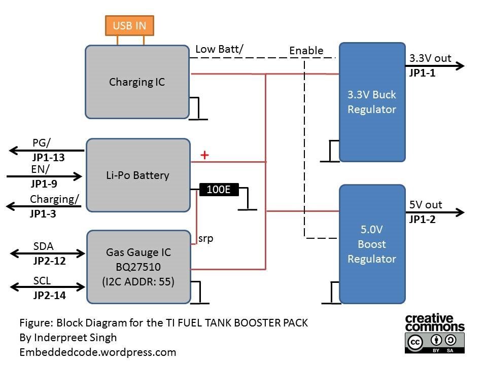
Now we do not want a USB in but a solar panel instead. Also I really have no need to gauge the battery either so thats out too. Instead I will use the BQ25504 to charge the Li-ion battery. In this case, we can also use a super cap like 1farad or so because the Wolverine LP really can work on that. Unfortunately, the sensors use up a lot more power so I left that part for an expansion for later. Next the buck and boost converter and for that we are using the TPS51200 and TPS62740. These generate the 5V and 3V for various parts. Each of these has an enable pin so I can shut them down too. This is our basic requirement and its quite simple. So lets start making the ckt. Eagle!!!!!


The Schematic

There are a couple of ways you can get a reference design but the application circuits in the datasheet are usually good enough. These are shown below.

image

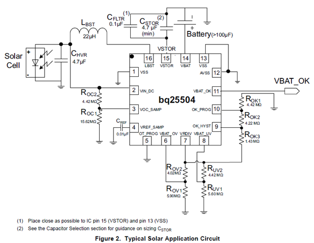
Thats the BQ25504. Pretty simple...
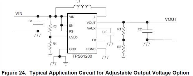
image

and the TPS61200

image

and the TPS62740


I can use these as is but I chose to dig a little deeper. I went on to find application notes for these and the circuits were more or less the same. So I can start making the circuit in eagle? Not so fast... Eagle has a lot of parts but you will need to make these yourself. I did and there are good tutorials on how to make parts in eagle from adafruit and sparkfun. The process is a little tedious but very satisfying.


The schematic I made looks like this...

image

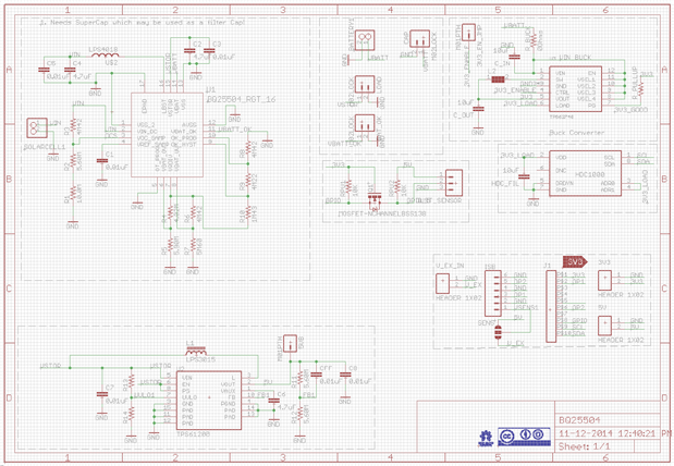
The schematic is self explanatory except for a few things. I added a connector for a sensor module which operates at 5V. Another module is used to interface a different sensor module. I probably should have added a voltage divider to the ADC but I simply missed that actually. That can be rectified but cutting the track and adding it between the connector. There is also a connector to connect it to the LaunchPad but its not a booster pack and I will explain why later.


The best laid layout

The next part is to layout the board. Everyone has a system for doing this and I have mine. When I start making the schematic, I finish a part such as the BQ25504 and its parts and jump into the layout. I don't completely layout the board but just arrange the parts together as an estimate and then place it somewhere else. The reason is that it simplifies layouts later and I used to work with Cadence OrCAD which had the facility to group components together. On the layout, keep pressing N to get the next part in the selected group for placement and thats something very nice. In eagle I just club things together since the number of parts on the PCB are usually smaller.


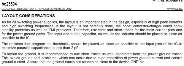
Before your start layout, see the datasheet for layout considerations like...

image

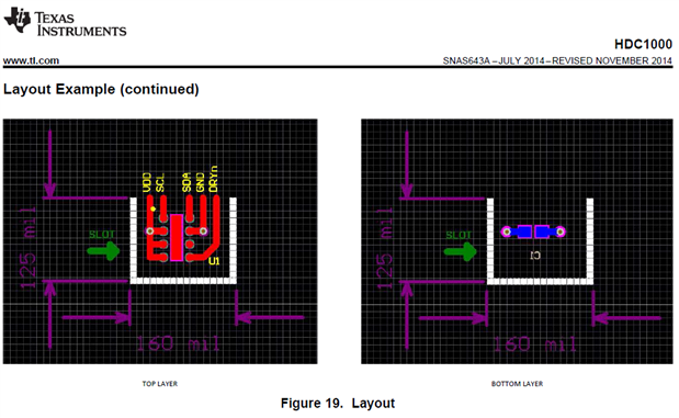
All said and done, you can even find sample layouts like the one for the HDC1000

image

Neat! So my final layout looks like...

image

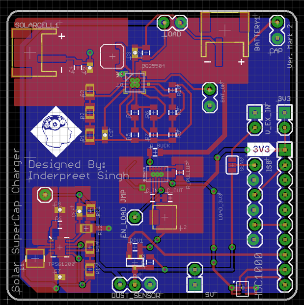
Each module was laid out separately and put into place. The thoughprocess is to use the least space but make the layout work. I used the seeed studios fabhouse so they ask for PCB sizes as a multiple of 5cm so I chose the least i.e. 5cm x 5cm. I make the outline 49mm x 49mm and then placed everything in it. The standard booster pack is much larger hence that was out of the question. Another aspect is that I know I will need to make changes later so I want to reduce the cost of prototype as much as possible. And lastly I want this thing to be reusable hence the enable pins, inputs and outputs all have a connector. So I can choose to use each part alone if I want. I ordered 10 of these so they should be useful for later projects as well.


I did NOT tent vias where vias are covered by the solder mask because I usually use these as test points to save unnecessary vias. The rev number is compulsory and I prefer rounded edges. Mounting holes I again avoid for small boards and instead I add single pin connectors(1 pin burg strips) at the corners or use a hot glue gun to make standoffs. image


One more trick is to upload these to OSHpark.com to see the result. I cannot use OSHPark because the shipping plus making is too much.


Thats about it. Once I get these manufactured, I will do a separate post for the pcb and parts.


Hope this helps.


Cheers

IP

  • Sign in to reply

Top Comments

  • shabaz
    shabaz over 10 years ago +1
    Hi Inderpreet, Wow, very nice circuit. The schematic is neatly laid out too! It's great to see people doing so much surface-mount custom PCB design, switching power design and low-signal analog sensor…
  • michaelwylie
    michaelwylie over 10 years ago in reply to ipv1 +1
    No, I didn't see anything wrong . The TPS62740 can handle up to 300 mA, I was just curious how close you would be to the limit and at what efficiency you would be running.
  • ipv1
    ipv1 over 10 years ago in reply to tomaja +1
    There is an under voltage programmable via a voltage divider. Got it covered (R13 and R14) Besides I am using a cellphone battery which has in built protection so should not be a problem.
  • tomaja
    tomaja over 10 years ago in reply to michaelwylie

    You're welcome image

    • Cancel
    • Vote Up 0 Vote Down
    • Sign in to reply
    • More
    • Cancel
  • michaelwylie
    michaelwylie over 10 years ago in reply to tomaja

    I see now, in my products we never sourced any batteries that didn't have the PCM. Thanks for the info.

    • Cancel
    • Vote Up +1 Vote Down
    • Sign in to reply
    • More
    • Cancel
  • tomaja
    tomaja over 10 years ago in reply to michaelwylie

    Oh, no. All my LiPo batteries are just simple LiPo cells connected in series (2-3 cells in series, but people have more complicated setups). I use them for my RC multi-rotors and airplanes.

    You have to monitor battery level during flight to save it (often using telemetry). I once left the transmitter ON (I use LiFe battery there) during night and woke up to see my battery puffed.

    I guess the reason for not including protection inside batteries is the price of this circuit in case of these high current batteries (e.g.. 40-50A).

    • Cancel
    • Vote Up 0 Vote Down
    • Sign in to reply
    • More
    • Cancel
  • michaelwylie
    michaelwylie over 10 years ago in reply to tomaja

    I was under the impression that most, if not all, Li-Po batteries have a PCM inside them to prevent deep discharge. I didn't know you could just purchase the Li-Po cell.

    • Cancel
    • Vote Up 0 Vote Down
    • Sign in to reply
    • More
    • Cancel
  • tomaja
    tomaja over 10 years ago in reply to ipv1

    Anyway, built-in protection is definitely a smart thing to choose image

    I opted out for a simple LiPo so I have to take care of things like that (i.e. BQ25504 will handle it).

    • Cancel
    • Vote Up +1 Vote Down
    • Sign in to reply
    • More
    • Cancel
>
element14 Community

element14 is the first online community specifically for engineers. Connect with your peers and get expert answers to your questions.

  • Members
  • Learn
  • Technologies
  • Challenges & Projects
  • Products
  • Store
  • About Us
  • Feedback & Support
  • FAQs
  • Terms of Use
  • Privacy Policy
  • Legal and Copyright Notices
  • Sitemap
  • Cookies

An Avnet Company © 2025 Premier Farnell Limited. All Rights Reserved.

Premier Farnell Ltd, registered in England and Wales (no 00876412), registered office: Farnell House, Forge Lane, Leeds LS12 2NE.

ICP 备案号 10220084.

Follow element14

  • X
  • Facebook
  • linkedin
  • YouTube