element14 Community
element14 Community
    Register Log In
  • Site
  • Search
  • Log In Register
  • About Us
  • Community Hub
    Community Hub
    • What's New on element14
    • Feedback and Support
    • Benefits of Membership
    • Personal Blogs
    • Members Area
    • Achievement Levels
  • Learn
    Learn
    • Ask an Expert
    • eBooks
    • element14 presents
    • Learning Center
    • Tech Spotlight
    • STEM Academy
    • Webinars, Training and Events
    • Learning Groups
  • Technologies
    Technologies
    • 3D Printing
    • FPGA
    • Industrial Automation
    • Internet of Things
    • Power & Energy
    • Sensors
    • Technology Groups
  • Challenges & Projects
    Challenges & Projects
    • Design Challenges
    • element14 presents Projects
    • Project14
    • Arduino Projects
    • Raspberry Pi Projects
    • Project Groups
  • Products
    Products
    • Arduino
    • Avnet Boards Community
    • Dev Tools
    • Manufacturers
    • Multicomp Pro
    • Product Groups
    • Raspberry Pi
    • RoadTests & Reviews
  • Store
    Store
    • Visit Your Store
    • Choose another store...
      • Europe
      •  Austria (German)
      •  Belgium (Dutch, French)
      •  Bulgaria (Bulgarian)
      •  Czech Republic (Czech)
      •  Denmark (Danish)
      •  Estonia (Estonian)
      •  Finland (Finnish)
      •  France (French)
      •  Germany (German)
      •  Hungary (Hungarian)
      •  Ireland
      •  Israel
      •  Italy (Italian)
      •  Latvia (Latvian)
      •  
      •  Lithuania (Lithuanian)
      •  Netherlands (Dutch)
      •  Norway (Norwegian)
      •  Poland (Polish)
      •  Portugal (Portuguese)
      •  Romania (Romanian)
      •  Russia (Russian)
      •  Slovakia (Slovak)
      •  Slovenia (Slovenian)
      •  Spain (Spanish)
      •  Sweden (Swedish)
      •  Switzerland(German, French)
      •  Turkey (Turkish)
      •  United Kingdom
      • Asia Pacific
      •  Australia
      •  China
      •  Hong Kong
      •  India
      •  Korea (Korean)
      •  Malaysia
      •  New Zealand
      •  Philippines
      •  Singapore
      •  Taiwan
      •  Thailand (Thai)
      • Americas
      •  Brazil (Portuguese)
      •  Canada
      •  Mexico (Spanish)
      •  United States
      Can't find the country/region you're looking for? Visit our export site or find a local distributor.
  • Translate
  • Profile
  • Settings
In the Air Design Challenge
  • Challenges & Projects
  • Design Challenges
  • In the Air Design Challenge
  • More
  • Cancel
In the Air Design Challenge
Blog [Firecracker Analyzer] Messing with an I2C LCD and using the BUS PIRATE
  • Blog
  • Forum
  • Documents
  • Polls
  • Files
  • Events
  • Mentions
  • Sub-Groups
  • Tags
  • More
  • Cancel
  • New
  • Share
  • More
  • Cancel
Group Actions
  • Group RSS
  • More
  • Cancel
Engagement
  • Author Author: ipv1
  • Date Created: 6 Dec 2014 1:28 PM Date Created
  • Views 1528 views
  • Likes 2 likes
  • Comments 6 comments
  • iot_firecracker
  • lcd
  • i2c
  • iot_ip
  • in_the_air
Related
Recommended

[Firecracker Analyzer] Messing with an I2C LCD and using the BUS PIRATE

ipv1
ipv1
6 Dec 2014

  • The LCD itself
  • First things first...
  • The bus pirate.
  • On to the bus!
  • Conclusion

I got one of these (The LCD!The LCD!) LCDs from the budget and the motive is to use them to display air quality. Low and behold I got them and these things are tiny... I mean more than I thought. BUT they should get the job done. This post is a little one where I try and get it to work and experiment with I2C. Lets go!
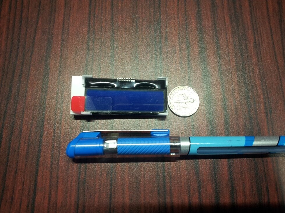
image


The LCD itself

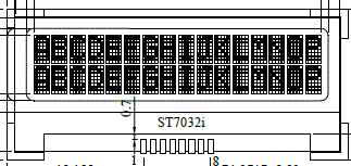
To be honest the features of this LCD are great but the cost is a little higher than I would like. The special thing about these is that they work at 3.3V which means they can be directly connected to my Launchpads. Great! Now how do I get em to work. The datasheet is available as with all element14 parts and you can download it for use. I will take out the parts that we need and discuss.


Shabaz sir used it in his posts about the CC3200 and he did it effortlessly. I had to mess with somethings hence I am posting a bit of my experience.


First things first...

The pin configuration. Before we start with the software lets ready the hardware and for that we need to know about the pin config. Its in the datasheet and the useful parts are:


image

image


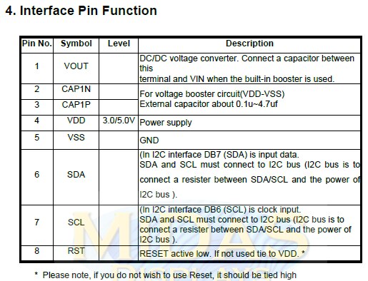
Brilliant now this means that  I can work with only 4 Pins. I need the VDD, VSS(GND), SDA and SCL. I can tie the reset and everything around. I am not going to make footprints or PCBs for this thing so I will directly solder everything in place. The pins are connected as:

1 - VOUT , 4 - VDD and 8 - RST to the 5V output from the CC3200 Launchpad. Why 5V? Because if you want to run it off the 3.3V then you need to add two caps. I will save those caps and use the 5V available on the LP.

5- VSS to Ground

6 - SDA to the I2C SDA Pin

7- SCL to the I2C SCL Pin


Done!

4 pins is all I need. If I need to reset it I can do it in software OR power the thing OFF and ON. Great!

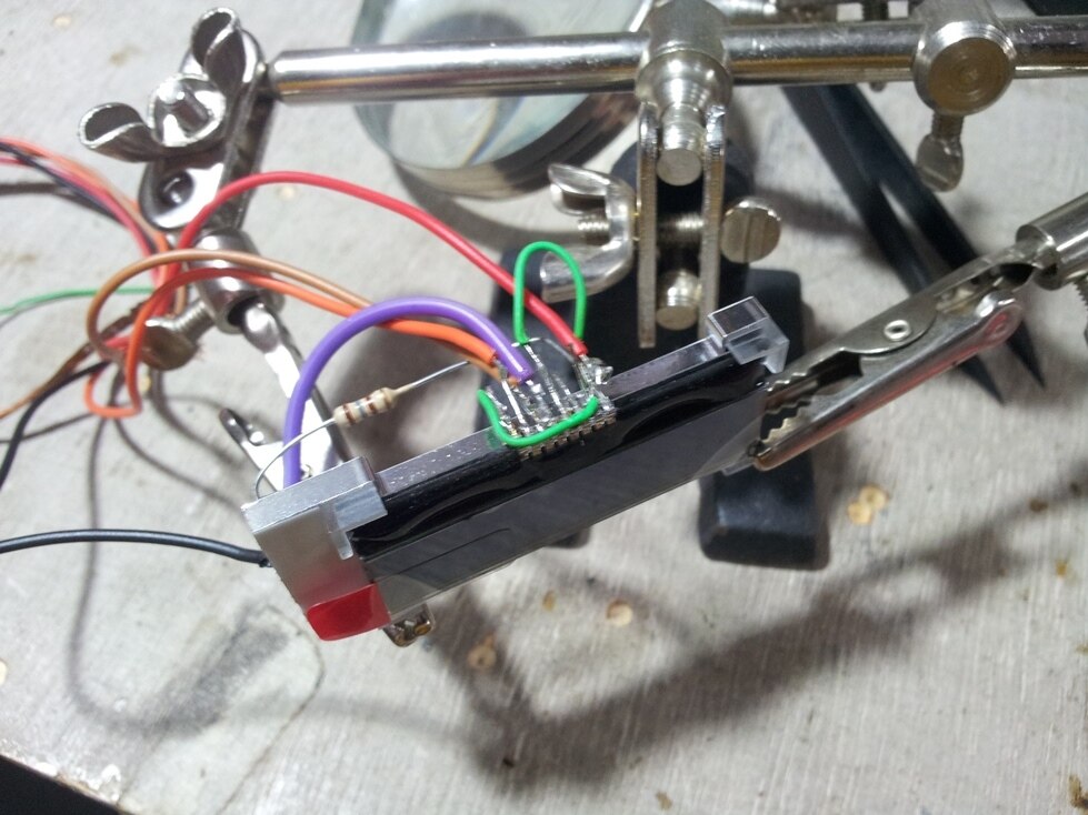
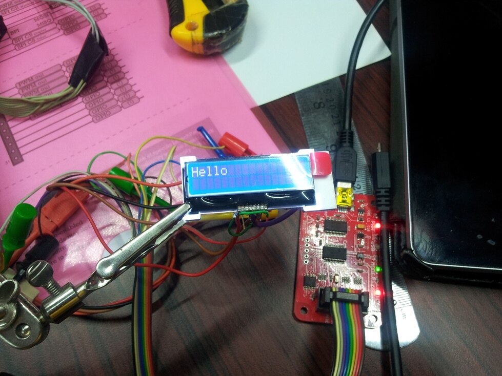
The results of my soldering is shown below. In my deficen I would like to say that I do not have the finer tips for the soldering station so this will have to do.


image


The bus pirate.

I would like to run the LP directly with the LCD but there is a problem. I don't want to mess with code then find out that my soldering was dry. So I chose to use the Bus Pirate.

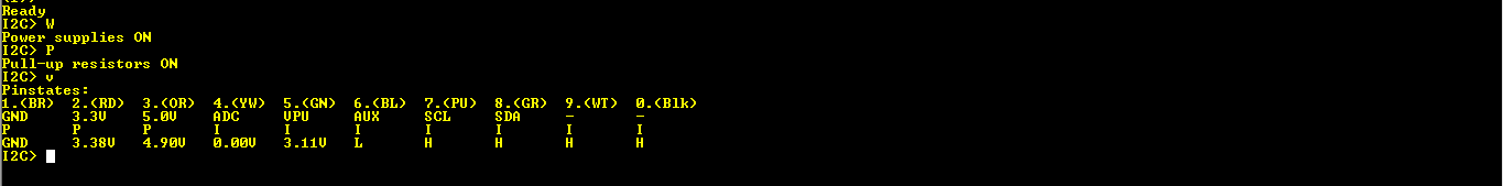
For thos who dont know, the bus pirate is a small tool that can be used with most serial bus protocols to debug and analyse them. Here I will be using it for I2C. Hooking it up is easy. The above four pins to the pins on the pirate and done! Well one more thing. The I2C bus needs pull-ups and the voltage of these pull ups matters for the controllers being used. I want the bus to go 3V3 so I can solder some external pullups. The simpler solution is that there is a Pull up connection on the BP which can be enabled or disabled in Software. Any voltage 3V3 or 5V can be selected externally using the provided pin and so I connected the Pullup wire to the 3V3 generated by the BP itself. Neat!


image

image

image


On to the bus!

There are a gazillion tutorials for the I2C bus on the net so I wont bother. The signaling is not important here but what is important is the protocol itself.

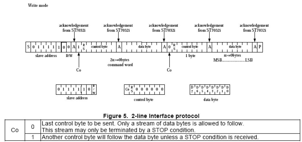
In order to talk to a device, the bus is pinged with a start signal.(For signalling details, google it! or PM me.) Next the address of the device to be hailed is sent. The addersses are 7 bit with the last bit signifiying read or write operation. Next data or commands are sent post which the device sends an ACK or acknowledge for each byte successfully received. This makes sure you are talking to something. Lets go by example here.


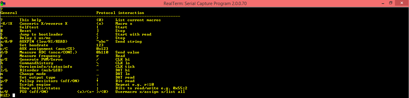
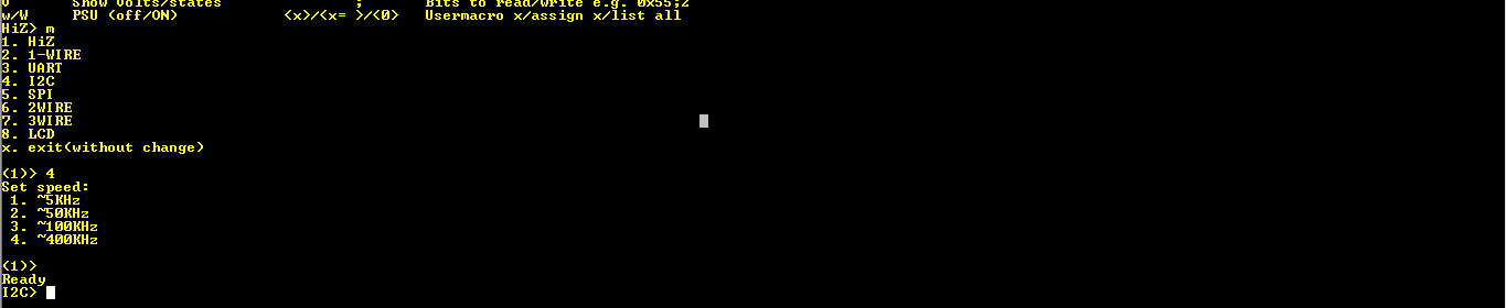
The first thing here is the address. The buspirate is used via a serial terminal program. After bringing it into I2C mode and enabeling the power and pullups, we try to talk to the LCD. Its address is 0b01111100 where the last bit is 0 for write operations. Hence for a read operation, we would use 0x7d. That simple. A quick look at the datasheet...


image


Easy right.. OK moving on.


We need to send it something that tells it that I want to send commands to initialize it. These commands also include resetting the LCD and moving the cursor around. So how do we do that?

The next byte we send will be 0x00 if we want to send a single command.

I made the string in notepad and pasted it into the realterm console as:
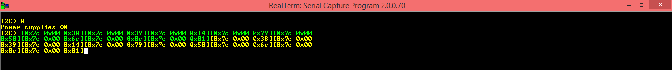
 

image

press enter and...

image


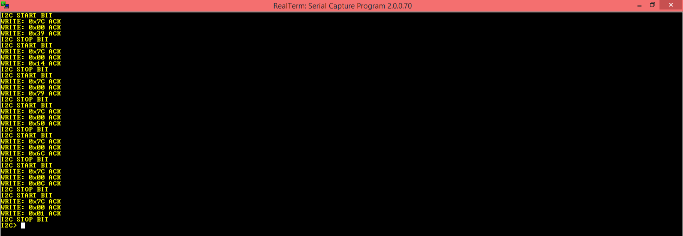
The ACKs means the LCD is present and responding. Good. Now to print something. Now the Datasheet has a table that you can decode but I have a trick. All the characters are assigned their ascii code and you can go to asciitable.com and get the hex values directly.


Copy and paste the string into the console and...

image


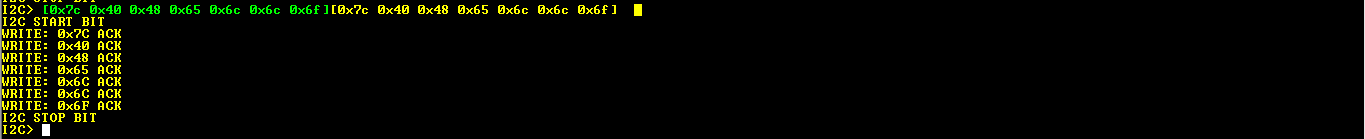
The Hello pops up on the LCD.

image


Conclusion

A lot of work just to get a hello but it is worth it in the long run. I hope this helps people thinking about adding an LCD to their project. Graphical LCDs are also possible but this is just smaller and quicker.

Cheers,

IP

  • Sign in to reply

Top Comments

  • ipv1
    ipv1 over 10 years ago in reply to mcb1 +1
    Thank you Sir, The ones I got can work 5v and 3v3 both. Useful for launchpads, BBB and RPi etc I think they recently increased the pricing at e14 because when I first saw it, it was less than half of what…
  • ipv1
    ipv1 over 10 years ago in reply to mcb1

    Thank you Sir,

    The ones I got can work 5v and 3v3 both. Useful for launchpads, BBB and RPi etc

    I think they recently increased the pricing at e14 because when I first saw it, it was less than half of what they are now. When I contacted sales they just never responded image

    Pricing gets a bit better in bulk though.

    • Cancel
    • Vote Up +1 Vote Down
    • Sign in to reply
    • More
    • Cancel
  • mcb1
    mcb1 over 10 years ago

    Nice job.

    The I2C version displays offered on some of the asian sites have the option of 3v3 operation.

    They have an extra chip to drive the LCD part, and I accidently got one and wondered why it wouldn't work on 5v, no matter how I set the contrast.


    You are right about the price for such a simple device ...


    mark

    • Cancel
    • Vote Up 0 Vote Down
    • Sign in to reply
    • More
    • Cancel
  • ipv1
    ipv1 over 10 years ago in reply to DAB

    Good advice sir,

    I tinned and tried that. Unfortunately the contacts are so fine and close to each other and the tip so big that it shorts out the consecutive contacts.

    In the end I had to manually space out the contacts and then do as you advised. image

    • Cancel
    • Vote Up 0 Vote Down
    • Sign in to reply
    • More
    • Cancel
  • DAB
    DAB over 10 years ago

    You can put solder on the wires with your big tips and then just touch the wire to your connection and heat it from the top.


    The solder will flow off the wire and on to the contacts.


    Just make sure you clean the contacts and put a bit of flux on the contacts before you start.


    DAB

    • Cancel
    • Vote Up 0 Vote Down
    • Sign in to reply
    • More
    • Cancel
  • ipv1
    ipv1 over 10 years ago in reply to shabaz

    Hello sir,

    I have the same grievance since it was a pain to solder connections.

    As for the hd44780 series, I use the mcp23009 as an i2c expander and then connect it to the micro. The problem is its all 5v and its big and bulky. These LCDs are just so small and convenient... Except for the connector.

    Thanks for pointing them out to me.

    Sincerely,

    IP

    • Cancel
    • Vote Up 0 Vote Down
    • Sign in to reply
    • More
    • Cancel
>
element14 Community

element14 is the first online community specifically for engineers. Connect with your peers and get expert answers to your questions.

  • Members
  • Learn
  • Technologies
  • Challenges & Projects
  • Products
  • Store
  • About Us
  • Feedback & Support
  • FAQs
  • Terms of Use
  • Privacy Policy
  • Legal and Copyright Notices
  • Sitemap
  • Cookies

An Avnet Company © 2025 Premier Farnell Limited. All Rights Reserved.

Premier Farnell Ltd, registered in England and Wales (no 00876412), registered office: Farnell House, Forge Lane, Leeds LS12 2NE.

ICP 备案号 10220084.

Follow element14

  • X
  • Facebook
  • linkedin
  • YouTube