element14 Community
element14 Community
    Register Log In
  • Site
  • Search
  • Log In Register
  • Community Hub
    Community Hub
    • What's New on element14
    • Feedback and Support
    • Benefits of Membership
    • Personal Blogs
    • Members Area
    • Achievement Levels
  • Learn
    Learn
    • Ask an Expert
    • eBooks
    • element14 presents
    • Learning Center
    • Tech Spotlight
    • STEM Academy
    • Webinars, Training and Events
    • Learning Groups
  • Technologies
    Technologies
    • 3D Printing
    • FPGA
    • Industrial Automation
    • Internet of Things
    • Power & Energy
    • Sensors
    • Technology Groups
  • Challenges & Projects
    Challenges & Projects
    • Design Challenges
    • element14 presents Projects
    • Project14
    • Arduino Projects
    • Raspberry Pi Projects
    • Project Groups
  • Products
    Products
    • Arduino
    • Avnet & Tria Boards Community
    • Dev Tools
    • Manufacturers
    • Multicomp Pro
    • Product Groups
    • Raspberry Pi
    • RoadTests & Reviews
  • About Us
  • Store
    Store
    • Visit Your Store
    • Choose another store...
      • Europe
      •  Austria (German)
      •  Belgium (Dutch, French)
      •  Bulgaria (Bulgarian)
      •  Czech Republic (Czech)
      •  Denmark (Danish)
      •  Estonia (Estonian)
      •  Finland (Finnish)
      •  France (French)
      •  Germany (German)
      •  Hungary (Hungarian)
      •  Ireland
      •  Israel
      •  Italy (Italian)
      •  Latvia (Latvian)
      •  
      •  Lithuania (Lithuanian)
      •  Netherlands (Dutch)
      •  Norway (Norwegian)
      •  Poland (Polish)
      •  Portugal (Portuguese)
      •  Romania (Romanian)
      •  Russia (Russian)
      •  Slovakia (Slovak)
      •  Slovenia (Slovenian)
      •  Spain (Spanish)
      •  Sweden (Swedish)
      •  Switzerland(German, French)
      •  Turkey (Turkish)
      •  United Kingdom
      • Asia Pacific
      •  Australia
      •  China
      •  Hong Kong
      •  India
      •  Korea (Korean)
      •  Malaysia
      •  New Zealand
      •  Philippines
      •  Singapore
      •  Taiwan
      •  Thailand (Thai)
      • Americas
      •  Brazil (Portuguese)
      •  Canada
      •  Mexico (Spanish)
      •  United States
      Can't find the country/region you're looking for? Visit our export site or find a local distributor.
  • Translate
  • Profile
  • Settings
Inductive Sensing
  • Challenges & Projects
  • Design Challenges
  • Inductive Sensing
  • More
  • Cancel
Inductive Sensing
Blog Inductive Sensing Design Challenge: USB Microphone based on the LDC1000 Inductance to Digital Converter (week 1)
  • Blog
  • Forum
  • Documents
  • Files
  • Events
  • Mentions
  • Sub-Groups
  • Tags
  • More
  • Cancel
  • New
  • Share
  • More
  • Cancel
Group Actions
  • Group RSS
  • More
  • Cancel
Engagement
  • Author Author: Former Member
  • Date Created: 26 Apr 2014 6:40 PM Date Created
  • Views 3084 views
  • Likes 1 like
  • Comments 9 comments
  • inductive_sensing
  • eagle
  • inductive_sensing_challenge
  • microphone
  • farnell
  • usb
  • ldc1000
  • texas_instruments
  • road_test
Related
Recommended

Inductive Sensing Design Challenge: USB Microphone based on the LDC1000 Inductance to Digital Converter (week 1)

Former Member
Former Member
26 Apr 2014

Hi everyone, my name is Sammy Peiren. This is the first blog post for my entry in the inductive sensing design challenge. The basic idea is to build a USB microphone based on the inductance to digital principle. Since the LDC1000 provides a digital output, it should be possible to get a USB connection.


image


To understand how I plan to detect sound with the LDC1000 I will give a short overview of the basic idea:

Imagine a point source that emits sound waves. As the waves are produced from the source, they propagate by vibration of particles in a medium (for example open air).


If a sound wave strikes a flexible object, a portion of the total energy will be reflected and another part will be transferred into a vibration of the object (absorption).

Some energy (heat) will be lost as the wave travels through the object and encounters friction from the material. Sound waves travel faster in a dense medium, thus the sound will be refracted by its encounter with a solid object. This is illustrated in the following figure:

image


Imagine we take a flexible plate and apply a sound wave to it. As the sound wave travels through the plate it will vibrate resulting in a slight flexing. The next figure shows an exaggerated example of this. Imagine we observe the position of the plate (by position we mean the nearest point on any part of the plate) from a certain point. If no sound wave is applied, the distance between the plate and the observation point is equal to A. In the second situation a sound wave strikes the plate and the plate flexes slightly inward. From our observation point, the distance of the plate is now equal to C. The difference between the original idle position of the plate and the flexed position is exactly B. In the third situation, the plate flexes back to the other side. This results in a new relative position which is equal to D. This is exactly equal to the original idle position plus B or C plus two times B.


image


The relative position of the plate can be plotted versus time as shown on the following figure:

image


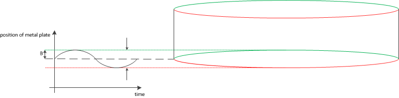
The LDC1000 is capable of detecting the movement of a conductive surface so if we were to use a conductive plate and the plate were sufficiently flexible, it should be possible to measure the movement of the plate by using inductive sensing.


But how does the vibration of a piece of metal translate into something we can hear? If we look at this in terms of sound there are two factors that will determine the character of the sound:

-the amplitude of the vibrations will correspond to the loudness of the sound

-the frequency of the vibrations will correspond to the pitch of the sound


We can plot the response of the microphone to various frequencies. The frequency response, determined by the material and the surrounding structures tells us how much of the vibration is transferred at a certain frequency. In our case the frequency response is also determined by the sensor frequency (to get a decent response time and output data rate the sensor frequency needs to be high enough). As shown in the next figure it is very common to use a logarithmic frequency axis and a logarithmic value for the amplitude (the decibel).

http://www.shure.co.uk/dms/shure/products/microphones/frequency-curves/sm/frequency-response_sm58/frequency-response_sm58.gif?1255946787

source: SM58 The legendary vocal microphone


There are other parameters that will determine how good the microphone works:

The dynamic range of the microphone tells us what the minimum and maximum amplitude of the vibration is we can detect. There are also various parameters that will determine what the dynamic range of the LDC1000 <-> transducer combination will be including the distance of the transducer, the construction of the coil, RP_min and RP_max.


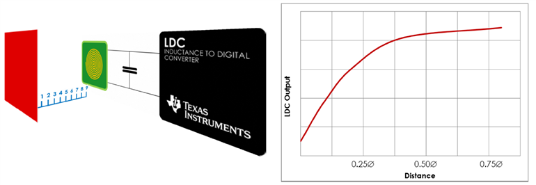
The main advantages of using the LDC1000 are the high sensitivity and dynamic range and the fact that it has a digital output. Since the LDC1000 only requires a coil and a conductive target, there are also no rare-earth magnets required. I do expect some difficulties as the basic setup shows that the LDC output is not linear for a basic position measurement (see figure).


image


I hope to learn a lot from this project and I'm sure it will be a very interesting project. Be sure to follow my blog if you are interested in inductive sensing and/or sound. This will be a rather experimental project, but you can expect a thorough explanation of all the steps, backed up by measurements and calculations.


The first few weeks will consist of getting to know the capabilities of the LDC1000 and its limitations. Once I receive the LDC1000EVM I hope to get started with my basic experiments, so stay tuned!

  • Sign in to reply
Parents
  • dougw
    dougw over 11 years ago

    Interesting project Sammy,

    One issue you are probably pondering, but the readership may not be aware of, is that the moving element and its mount with have natural frequencies where they will vibrate or oscillate when excited. The best way to prevent these vibrations from distorting the audio signal is to ensure all natural frequencies are above the hearing range. This usually means very stiff and very small moving elements, however a mounting structure that allows the element to move also allows it to vibrate. Maybe if the natural frequency of the mount is below the hearing range it would help. For example if you hang a metal disk from 2 threads such that the pendulum frequency is below 20 Hz, then the disk is free to move without "hearing" the swing of the pendulum. Any vertical frequency modes associated with stretching the thread wouldn't register on the sensor because of the direction, also the sound waves wouldn't be providing much vertical excitation. Anyway I am sure it will be fun overcoming the various challenges in this project.

    Doug

    • Cancel
    • Vote Up 0 Vote Down
    • Sign in to reply
    • More
    • Cancel
  • Former Member
    Former Member over 11 years ago in reply to dougw

    Hi Douglas,


    Yes I had thought of that, but I'm not quite sure how I'll eventually mount the transducer or even what shape it will have. Like DAB said I will probably start with a stretched piece of plastic or aluminum foil on some container (I was thinking about using a piece of cardboard tube, not sure what the resonance frequency would be). I had also thought of trying something like a ribbon mic, where you use a corrugated piece of metal to detect vibrations. Anyway, the mounting structure will certainly have an influence on the frequency response. I will keep your remarks in mind when building a prototype, thanks!

    • Cancel
    • Vote Up 0 Vote Down
    • Sign in to reply
    • More
    • Cancel
Comment
  • Former Member
    Former Member over 11 years ago in reply to dougw

    Hi Douglas,


    Yes I had thought of that, but I'm not quite sure how I'll eventually mount the transducer or even what shape it will have. Like DAB said I will probably start with a stretched piece of plastic or aluminum foil on some container (I was thinking about using a piece of cardboard tube, not sure what the resonance frequency would be). I had also thought of trying something like a ribbon mic, where you use a corrugated piece of metal to detect vibrations. Anyway, the mounting structure will certainly have an influence on the frequency response. I will keep your remarks in mind when building a prototype, thanks!

    • Cancel
    • Vote Up 0 Vote Down
    • Sign in to reply
    • More
    • Cancel
Children
No Data
element14 Community

element14 is the first online community specifically for engineers. Connect with your peers and get expert answers to your questions.

  • Members
  • Learn
  • Technologies
  • Challenges & Projects
  • Products
  • Store
  • About Us
  • Feedback & Support
  • FAQs
  • Terms of Use
  • Privacy Policy
  • Legal and Copyright Notices
  • Sitemap
  • Cookies

An Avnet Company © 2025 Premier Farnell Limited. All Rights Reserved.

Premier Farnell Ltd, registered in England and Wales (no 00876412), registered office: Farnell House, Forge Lane, Leeds LS12 2NE.

ICP 备案号 10220084.

Follow element14

  • X
  • Facebook
  • linkedin
  • YouTube