


This week I focused mostly on the software for the LDC1000EVM. There are many questions on the ask TI forum about the protocol which is used on the LDC1000EVM, but there is no real single answer. What is known is that the LDC1000EVM uses a USB CDC (Communcication Device Class) API which shows up as a virtual COM port. There are a bunch of protocols that you can use to communicate with the LDC1000EVM via the virtual COM port. First of all there is the legacy protocol which is used in the Matlab libraries and presumably also the National Instruments Labview libraries. This protocol is described in the ask TI forum FAQ as follows:
SPI reads and writes are passed though using a hybrid ASCII/numeric byte protocol:
Host to EVM:
[ Command | Register Address | Data ]
[ 2 hex chars (ASCII) | 2 hex chars (ASCII) | hex chars (width of 2, ASCII)... ]
EVM to Host 32bytes:
[ Command echo | Register Address echo | Data echo | Return Data (at zero-offset 8) ]
[ 2 hex chars (ASCII) | 2 hex chars (ASCII) | hex chars (width of 2, ASCII)... | Numeric Byte(s) ]
EVM to Host (Streaming of Polled Data, 16-bits L):
[ Rp raw data | Frequency Counter raw data ]
[ 1024 bytes | 1024 bytes ]
[ 16-bit Big Endian words x 512 | 16-bit Big Endian words x 512 ]
EVM to Host (Streaming of Polled Data, 24-bits L):
[ Rp raw data | Frequency Counter raw data ]
[ 1024 bytes | 1536 bytes ]
[ 16-bit Big Endian words x 512 | 24-bit Big Endian words x 512 ]
Data is streamed in chunks of 2048 bytes
The first 1024 bytes are Rp raw data, the rest are Frequency Counter raw data
Data is streamed Big Endian, 16-bit words
Samples are chronological (first word in buffer is first sample)
Commands are as follows:
Command_SPI_Byte_Write: "02"
Writes a byte to the LDC1000
send data length = 2 hex chars (ASCII); data: byte to write
return data length = 1 byte; data: numeric byte that was written
Command_SPI_Byte_Read: "03"
Reads a byte from the LDC1000
send data length = 0
return data length = 1 byte; data: numeric byte that was read
Command_Firmware_Version_Read: "09"
Reads the firmware version
send data length = 0
return data length = 4 bytes; data: numeric bytes, MSByte ... LSByte
Command_Timer_Interval: "08"
Sets the polling interval on the microcontroller for LDC1000 data
send data length = 4 numeric ASCII chars. Timer clock period. (e.g. "1234" = 24MHz/1234 = 19.4kHz ),
return data length = 2 bytes; data: numeric 16-bit word, little endian. Timer A0 Capture Compare Register 0 value.
Warning: Intervals faster than 35kHz are unsupported
Command_Start_Streaming 16-bits R, 16-bits L: "06"
Starts data polling and streaming to host
send data length = 0
return data length = 0
Command_Start_Streaming 16-bits R, 24-bits L: "0B"
Starts data polling and streaming to host
send data length = 0
return data length = 0
Command_Stop_Streaming: "07"
Stops data polling and streaming to host
send data length = 0
return data length = 0
Second, there is a way to communicate with the LDC1000EVM using just a simple terminal. The commands are as follows:
- ?: display menu
- 1: read proximity data
- 2: read frequency counter data
- 3: start streaming proximity and frequency counter data
- 4: stop streaming
- 5: speed up stream by 10ms
- 6: slow down stream by 10ms
- 7: cycle trough the leds on the LDC1000EVM as a test
- 8: cycle trough the RPmin values to change the setting
- 9: cycle trough the RPmax values to change the setting
The following figure shows an example of starting a stream and changing the update rate.

This protocol is only useful if you need very basic information, because there is no way to directly access the LDC1000’s registers. You can however change the RPmin and RPmax values, but not in a very straightforward manner. The other limitation is that the minimum stream period is 10ms, which is not very fast at all.
Lastly, I’m pretty sure there is another way to communicate with the LDC1000EVM which might be more flexible. I noticed the LDC1000EVM GUI was able to update data at a pretty fast rate, but it couldn’t be using the legacy protocol, because, well… it’s considered legacy. Another option is that the LDC1000EVM GUI uses some other USB API instead of USB CDC, but I doubt that since it actually says ‘COM22’ on my front panel.

So I tried looking at the commands using SerialMon, which is basically a software tool that lets you monitor all data on a serial port (something similar to Wireshark, but then for serial ports). I set the sampling rate to 1Hz (you can get a lower sampling rate by changing the period, but not by changing the frequency) and waited for the commands to show up. The strange thing is that I didn’t recognize the structure of these commands. An example is shown on the next figure.


I tried entering these commands (for example: ‘4C300100009C’) in a serial terminal and they do work, but I’m not too keen on using them since I have no idea what they do and as far as I know these are completely undocumented. One could probably reverse engineer the command structure by looking at the firmware source, but that really doesn’t seem like the way to go.
Therefore I’ll stick to using the legacy protocol for now. I have done some tests in Matlab and I got a pretty decent data rate. The advantage of using Matlab is that operations such as an FFT are pretty trivial. The disadvantage is that it’s not very fast at all and there is no easy way to playback realtime audio. A figure of the data is shown below.

I think the better solution would be to make something similar in C# with the free NAudio library. I also have more experience using C# than I do with Matlab. The plan is to first get the fastest possible data rate using the LDC1000EVM. It should be possible to keep track of the speed using a simple timer. I don't think there is much of a limit on the baudrate because there is no physical RS-232 connection, just USB. Next I’ll try displaying and playing back the data using NAudio. And finally I’ll implement the spectrum analyzer.
Here is what I have so far:
using System;
using System.Collections.Generic;
using System.Linq;
using System.Text;
using System.IO.Ports;
using NAudio.Wave;

namespace LDC1000_Audio_Interface
{
    public class LDC1000_StreamData
    {

        private SerialPort serialPort;
        private static WaveFormat waveFormat;
        private BufferedWaveProvider buffer;

        public LDC1000_StreamData()
        {
            serialPort = new SerialPort();
            serialPort.PortName = "COM22";
            waveFormat = new WaveFormat(44100, 16, 1);
            buffer = new BufferedWaveProvider(waveFormat);

        }
        public void StartStream()
        {
            string sampleRateCommand = "08AC4400"; //set sampling rate to 44100
            string enableCommand = "020B0100"; //enable conversion
            string startCommand = "06210000"; //start streaming data
            try
            {
                serialPort.Open();
                while (serialPort.BytesToRead > 0)
                {
                    byte b = (byte)serialPort.ReadByte();
                    Console.Write(b);
                }
                serialPort.Write(sampleRateCommand);
                serialPort.Write(enableCommand);
                serialPort.Write(startCommand);
                while (serialPort.BytesToRead > 0)
                {
                    byte b = (byte)serialPort.ReadByte();
                    Console.Write(b);
                }
            }
            catch (System.Exception ex)
            {
                startCommand = "";
            }

        }
        public void StopStream()
        {
            string stopCommand = "07210000"; //start streaming data
            try
            {
                serialPort.Write(stopCommand);
                serialPort.Close();
            }
            catch (System.Exception ex)
            {
                stopCommand = "";
            }

        }
    }
}

}


}
The best scenario would be a microphone that you can just plug in without the need for any additional software, therefore I might consider getting a second LDC1000EVM to try setting it up as a USB Audio device. Or just getting a MSP430 launch platform and starting from there. Once all system parameters are known, the microcontroller just needs to scale the proximity data to a useable value maybe with some filtering and then send it trough USB.
One other thing I checked out this week was the LDC1000 webbench tool. It is useful to get a ballpark idea of your system requirements, but I don't think it is very suited for precise calculations. It's also pretty limited because there are only three materials to choose from and you cannot change the thickness of the metal. This figure shows what is pretty much the limit of the LDC1000 if you use the webbench tool:
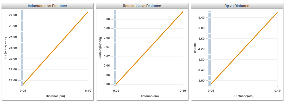
As you can see on the second graph, the resolution is almost linearily dependent on the distance of the target. At half a millimeter we still only get a resolution of 50nm, which is not enough according to my previous calculations. Even worse, the webbench presumes the use of stainless steel, which has a much higher permeability, so Aluminum will probably have a worse resolution. I'll still try to see what I can get out of the circular stretched membrane setup, but if the resolution cannot be improved or the displacement increased I will have to look for some other solution. A possible improvement might be the use of a wound coil or a coil with more layers, but I haven't found much information about that yet. One other thing to improve the resolution is the use of a very high sample rate and interpolating the results, but this wouldn't be a real improvement of the basic sensor system.
I have checked out alot of papers about inductive sensing which are very informative. If anyone wants something to read I can provide a list of useful references.
As you can see there is still lot's of work to be done, so until next week!

