element14 Community
element14 Community
    Register Log In
  • Site
  • Search
  • Log In Register
  • Members
    Members
    • Benefits of Membership
    • Achievement Levels
    • Members Area
    • Personal Blogs
    • Feedback and Support
    • What's New on element14
  • Learn
    Learn
    • Learning Center
    • eBooks
    • STEM Academy
    • Webinars, Training and Events
    • More
  • Technologies
    Technologies
    • 3D Printing
    • FPGA
    • Industrial Automation
    • Internet of Things
    • Power & Energy
    • Sensors
    • More
  • Challenges & Projects
    Challenges & Projects
    • Design Challenges
    • element14 presents
    • Project14
    • Arduino Projects
    • Raspberry Pi Projects
    • More
  • Products
    Products
    • Arduino
    • Dev Tools
    • Manufacturers
    • Raspberry Pi
    • RoadTests & Reviews
    • Avnet Boards Community
    • More
  • Store
    Store
    • Visit Your Store
    • Choose Another Store
      • Europe
      •  Austria (German)
      •  Belgium (Dutch, French)
      •  Bulgaria (Bulgarian)
      •  Czech Republic (Czech)
      •  Denmark (Danish)
      •  Estonia (Estonian)
      •  Finland (Finnish)
      •  France (French)
      •  Germany (German)
      •  Hungary (Hungarian)
      •  Ireland
      •  Israel
      •  Italy (Italian)
      •  Latvia (Latvian)
      •  
      •  Lithuania (Lithuanian)
      •  Netherlands (Dutch)
      •  Norway (Norwegian)
      •  Poland (Polish)
      •  Portugal (Portuguese)
      •  Romania (Romanian)
      •  Russia (Russian)
      •  Slovakia (Slovak)
      •  Slovenia (Slovenian)
      •  Spain (Spanish)
      •  Sweden (Swedish)
      •  Switzerland(German, French)
      •  Turkey (Turkish)
      •  United Kingdom
      • Asia Pacific
      •  Australia
      •  China
      •  Hong Kong
      •  India
      •  Korea (Korean)
      •  Malaysia
      •  New Zealand
      •  Philippines
      •  Singapore
      •  Taiwan
      •  Thailand (Thai)
      • Americas
      •  Brazil (Portuguese)
      •  Canada
      •  Mexico (Spanish)
      •  United States
      Can't find the country/region you're looking for? Visit our export site or find a local distributor.
  • Translate
  • Profile
Internet of the Backyard
  • Challenges & Projects
  • Design Challenges
  • Internet of the Backyard
  • More
  • Cancel
Internet of the Backyard
Blog [IoT_Grass #4] IoT Backyard Challenge GGMS - Time flies when waiting for grass to grow
  • Blog
  • Forum
  • Documents
  • Mentions
  • Sub-Groups
  • Tags
  • More
  • Cancel
  • New
Blog Post Actions
  • Subscribe by email
  • More
  • Cancel
  • Share
  • Subscribe by email
  • More
  • Cancel
Group Actions
  • Group RSS
  • More
  • Cancel
Engagement
  • Author Author: BigG
  • Date Created: 5 Oct 2014 11:27 PM Date Created
  • Views 193 views
  • Likes 2 likes
  • Comments 8 comments
  • iot_grass
  • iot_backyard
  • internet_of_things
Related
Recommended

[IoT_Grass #4] IoT Backyard Challenge GGMS - Time flies when waiting for grass to grow

BigG
BigG
5 Oct 2014

Thanks to an unseasonally warm September month I finally have plenty of long grass to work with...


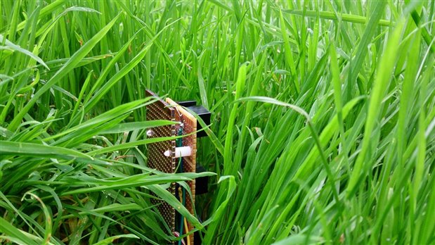
and the grass sensor node is coming along slowly but surely. Here is my first attempt at the grass node sitting in shorter grass... yes I mowed the grass too (well most of it as still need the long grass for testing).


By way of summary of progress.... not quite like clockwork...


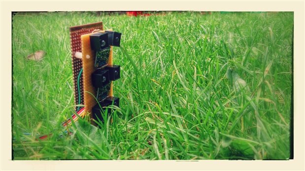
Quite a few mistakes were made on my first build attempt. Firstly, the placement of wiring was messy and then the gap right between the two boards to accommodate the battery was too narrow. I fell into the classic trap of rushing to build due to the tight deadline before thinking through the design. So word of advice, don't forget to some engineering before doing some making. I am a great fan of the Fritzing breadboard mode as this mode quickly validates your wiring layout and you get a nice visualisation too of how things are connected (2nd design of mine shown later on).


Anyhow, my first hack attempt very quickly flagged a shortcoming in my original design (so okay the rush to build did have a benefit in my case - so next tip, don't over analyse and wait till things are perfect before making something). It highlighted once again that both hardware design and software development have to be considered in tandem from the very start of a project. One feeds off the other, so don't treat as sequential steps. I had intended to use two Adafruit breakout boards, the TSL2591  as the top light detection sensor as had a greater dynamic range (to avoid saturation) and then 2 x TSL2561's for the middle and bottom sensors as these were cheaper and also one could change the I2C addresses with these boards so they would not conflict the TSL2591 (which you could not address). This seemed a reasonable approach from a hardware design point of view. However, once you start to look at the software development side, you immediately find yourself making more work for yourself trying to handle two types of I2C devices.


Hence I am now using 3 x TSL2561's, each with their own unique address (as this is possible) and all I needed to do in the software point is use the Adafruit open source library and create three instances of the class for top, middle and lower sensor. With I2C I simple join the SDA and SCL of each board and as they already have pullup resistors all the work was taken care of. As I was never planning to take continuous readings I have now decided to utilise the interrupt pin on one of the TSL2561's and set up a low light threshold trigger to wake up the grass node as I only want to take measurements when light is low (hence I will never have the saturation problem in this case). The interrupt feature is a really handy feature for my application.


So now that the main part of the sensor design was sorted, the next step was review the wiring layout to determine how many input output pins I needed to help determine which MCU would work best. I was fortunate enough to get hold of a LaunchPad MSP430G2553 for the purposes of seeing whether this MCU would do the trick. I used Energia as my method to get "to know" the board. I had no problems using Energia for the basic examples and the compile and upload process removed all the headaches I was getting when using CCS. Energia is a bit like buying a simple hatchback to drive and go about your business. I find this really helpful with the prototyping stage. With CCS, you are getting a high performance hatchback but you first have to train to become a mechanic as you would be expected rather than required to know the ins and outs of the engine and would need to adjust the suspension before you drive the vehicle. However, the Energia system needs to mature so expect a few quirks along the way. I did not have success using the TSL2561 library as it makes reference to AVR routines and I did not want to spend time just yet manually checking throught.


Also other tests did not quite go the way I wanted using I2C on the MSP430G2 board as it did not have enough memory to do what I needed to do (mainly because of all the extra debugging / test code I added to see how things are doing). Maybe once the code is optimised it would shrink down significantly to make this workable, as this board does have some good positives and compiles really easy. So I decided to stick with what I know best as this ensures all the logic is sorted out in the code, which then ultimately feeds back to choice of hardware (remember they are intrinsically linked).


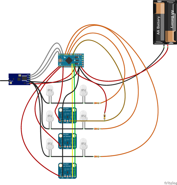
Here is the Fritzing wiring layout of the node design so far:


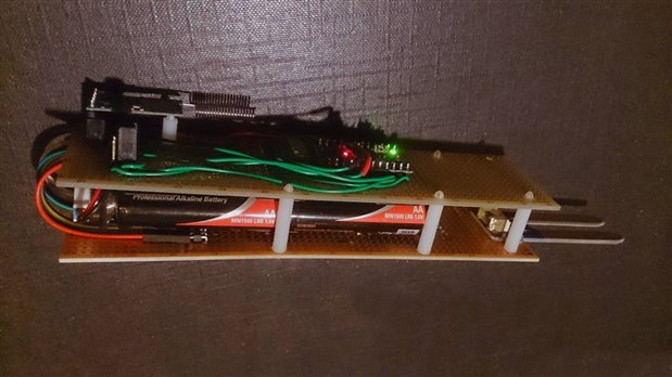
And here is the prototype all wired up and ready for its first tests:


The MCU board for the node to get me to first test of logic is an Arduino pro mini 3.3V as it has a reasonably efficient voltage regulator on board, which at least takes away that headache to get me started. However, I find putting Arduino's to sleep to really be a pain in the neck.


The node has a moisture sensor which doubles up as the means to peg the node into the ground. An optional temperature probe could also be included as the 3rd "peg" in the ground.


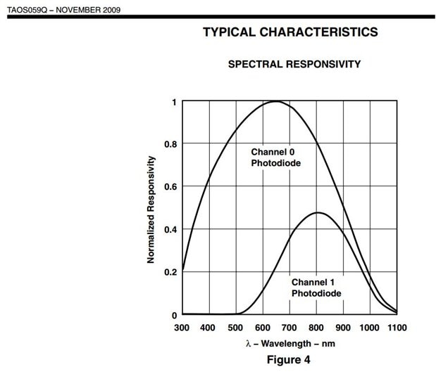
According to Spectral responsivity of light sensor (see chart) channel 1 is more sensitive closer to the 800nm range, so I decided to use two Infrared LED's at different wavelength, one at 890nm and one at 940nm to provide a better spectrum of light for the sensor to pick up. This will probably require tweaking down the line. I am also using LED's with a narrower beam angle of 10 to 15 degrees.


I am also using an HC12 433MHz serial RF device to handle communication between the node and the CC3200, which is the main controller and gateway to the internet. The aim would be to create a wireless sensor network using (most probably) the MQTT-SN messaging protocol if the CC3200 was externally powered rather than battery powered, as the CC3200 would act as my messaging broker. However, as the aim is for the CC3200 to operate off batteries or solar power with backup battery, this method would not work as the CC3200 has to sleep as well. So I need to have a means to wake up the CC3200 using the serial RF device first then it can process the messaging payload from the RF device and then it can go back to sleep again. Hence this will have to be interrupt driven.


To close off. I had put the CC3200 to one side for a couple of weeks to help the brain absorb and digest all the information. I will be getting back to this part of the project now that things are becoming much clearer and my first node is built.

Anonymous

Top Comments

  • DAB
    DAB over 7 years ago +1

    Are you just looking at grass height or are you thinking of doing a little crop stress analysis as well?


    DAB

  • shabaz
    shabaz over 7 years ago +1

    This is nice! Cool way to measure height.

    But I can imagine the conversation when people see a certain patch of your grass was not mowed.

    "You missed a bit"

    "That's for testing"

    <…

  • peteroakes
    peteroakes over 7 years ago in reply to shabaz +1

    More of an issue when someone else mows the lawn...


    Mow, Mow, Mow, Crunch... What was that


    Mow Mow mow


    Good job he made 2... or did he ?

  • BigG
    BigG over 7 years ago in reply to janisalnis

    That's a great idea. I note that there are already colour tracking algorithms out there which are written for basic MCU's so it is quite achievable. Programme languages such as processing could also be used as quite well suited for image analysis and you could also develop an app using processing for Android phone to analyse image too, once sent via wifi to smartphone. Naturally this would require some testing to get those empirical rules right to avoid false positives but should not that complex and not trying to recognise an image - it's merely analysis of colour density within a defined segment within the pixel matrix. It all depends on what colours are in the background. I would think this method may also determine grass density as well. Then its really up to the non technical stuff of "how cheap could you make it". One would need to ensure camera has right enclosure to work in high moisture area in the grass (dew / rain).  Other consideration is whether it will be a drop and leave solution or one where you place device to take sample readings and then remove device till the next time you wish to take another sample reading. So who knows, its certainly something to tinker with in the future.

    • Cancel
    • Up 0 Down
    • Reply
    • More
    • Cancel
  • janisalnis
    janisalnis over 7 years ago

    It would be easier and more precise to follow grass height using a camera.

    Could do simple image recognition - by counting green pixels.

    • Cancel
    • Up +1 Down
    • Reply
    • More
    • Cancel
  • BigG
    BigG over 7 years ago in reply to peteroakes

    LOL. There were 2 but the dog ate one of them... I wish. There are 2 but unfortunately one of them is not quite working as well as I hoped. I have to blame the maker, i.e. me, for that...


    As for the mowers who knows, maybe I'll have to make them biodegradable (means can sell more.. if they ever hit the shelves) or better still, maybe expand and make obstacle avoidance sensors for the mower to avoid those little mishaps.

    • Cancel
    • Up +1 Down
    • Reply
    • More
    • Cancel
  • BigG
    BigG over 7 years ago in reply to DAB

    Who knows. We'll have to wait and see what the data says. For me this is all about IoT development in a glass house so have no preconceptions... Mind you the only love to have "stress analysis" feature I could think of was to add in a little camera to capture those little rascals, i.e. dog owners rather than the dog, who fail to clean up after their dog has done its business on the grass... then can create some name and shame posters for the neighbourhood...

    • Cancel
    • Up 0 Down
    • Reply
    • More
    • Cancel
  • shabaz
    shabaz over 7 years ago in reply to peteroakes

    The day will come, mowers will need to be built and sold on a stripboard-resistant rating.

    This is the IoT, this is how we mow!!

    • Cancel
    • Up +1 Down
    • Reply
    • More
    • Cancel
>
Element14

element14 is the first online community specifically for engineers. Connect with your peers and get expert answers to your questions.

  • Members
  • Learn
  • Technologies
  • Challenges & Projects
  • Products
  • Store
  • About Us
  • Feedback & Support
  • FAQs
  • Terms of Use
  • Privacy Policy
  • Legal and Copyright Notices
  • Sitemap
  • Cookies

An Avnet Company © 2022 Premier Farnell Limited. All Rights Reserved.

Premier Farnell Ltd, registered in England and Wales (no 00876412), registered office: Farnell House, Forge Lane, Leeds LS12 2NE.

ICP 备案号 10220084.

Follow element14

  • Facebook
  • Twitter
  • linkedin
  • YouTube