


In this blog, I will test all the sensors individually with the Arduino.
Waterproof DS18B20 Digital temperature sensor testing
This temperature sensor uses the Dallas 1-Wire protocol and gives up to 12 bits of precision from the onboard digital-to-analog converter. This sensor works great with any microcontroller using a single digital pin and requires a bunch of code to parse out the communication. The sensor can be powered with a 3V to 5.5V power supply and consumes only 1mA during active temperature conversions.
One of the biggest advantages of DS18B20 is that multiple DS18B20s can coexist on the same 1-Wire bus. As each DS18B20 has a unique 64-bit serial code burned in at the factory, it’s easier to differentiate them from one another. This feature can be a huge advantage when you want to control many DS18B20s distributed over a large area.
Connection

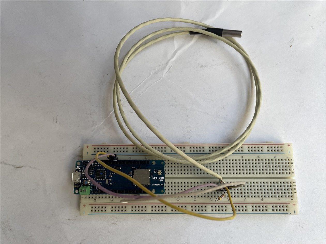
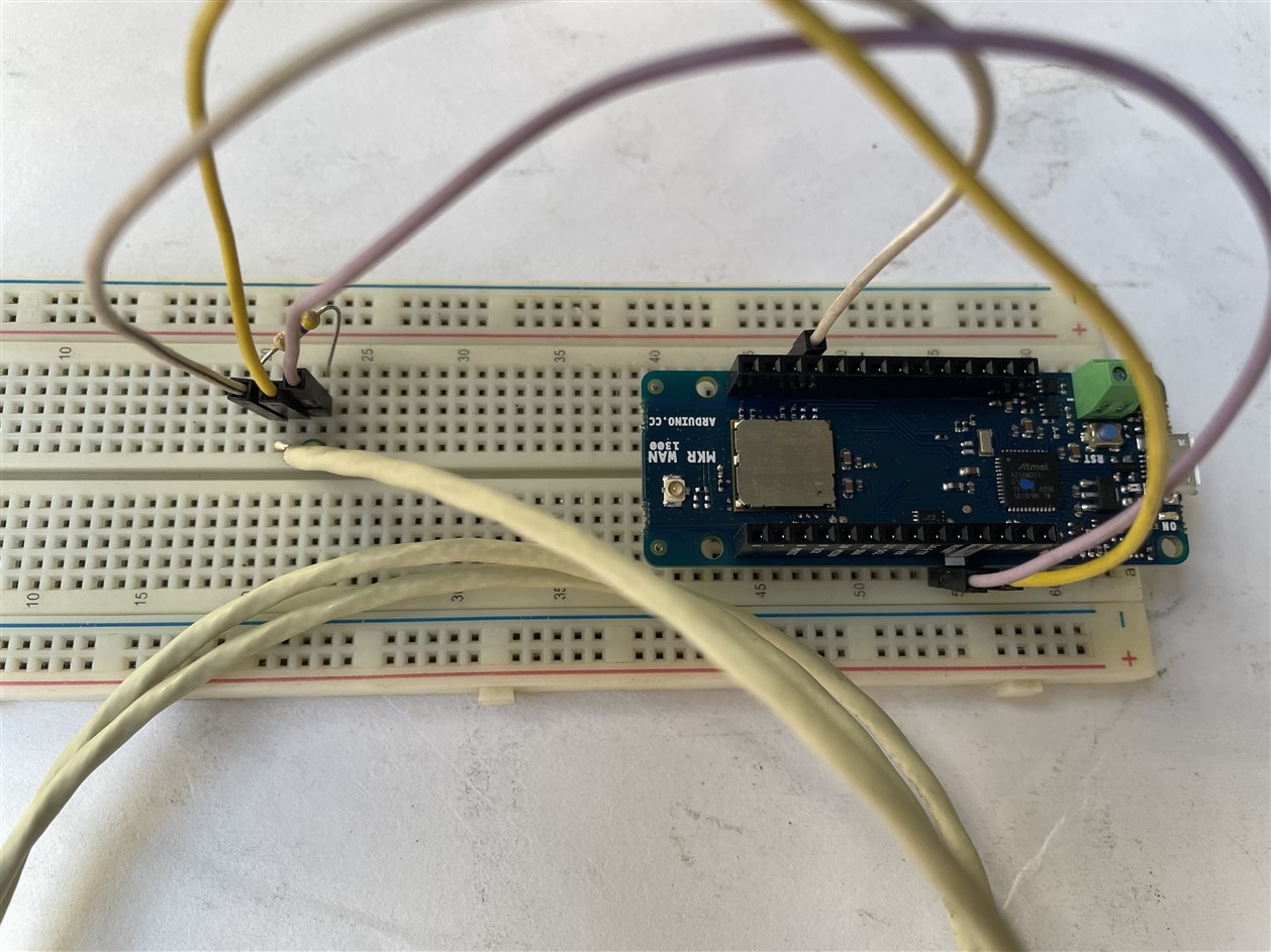
The connections are fairly simple. Start by connecting VDD to the 5V out pin on Arduino and GND to ground.
Next connect the remaining digital signal pin DQ to digital pin 2 on Arduino. You’ll also need to add the 4.7k pull-up resistor between the signal and power pin to keep the data transfer stable. (internal pull-ups on the arduino does not work)
Be careful to get the DS18B20 the right way around. If you put it the wrong way around, it will get hot and then break.
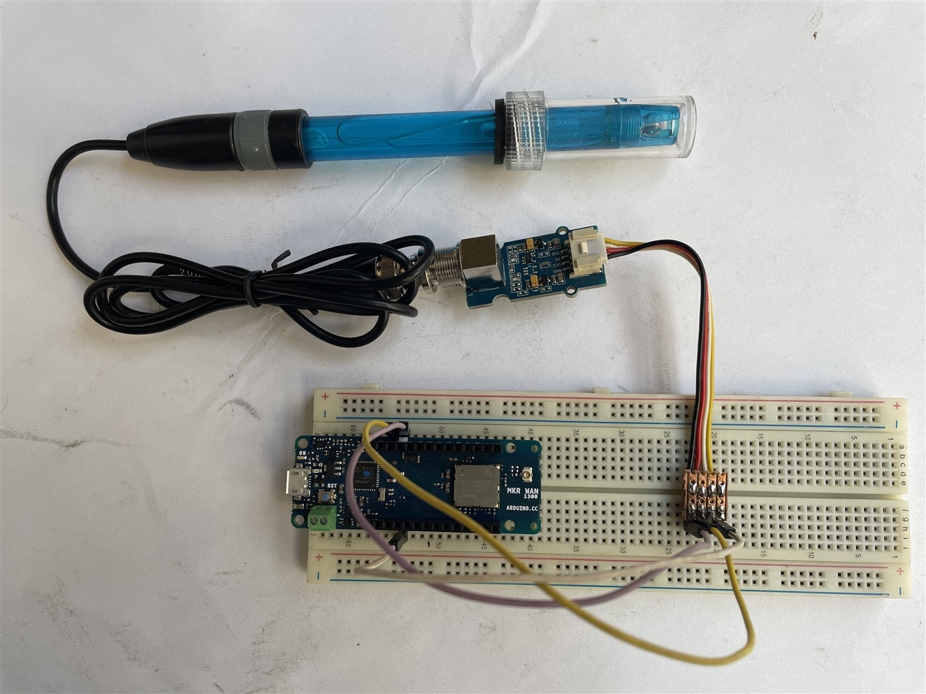
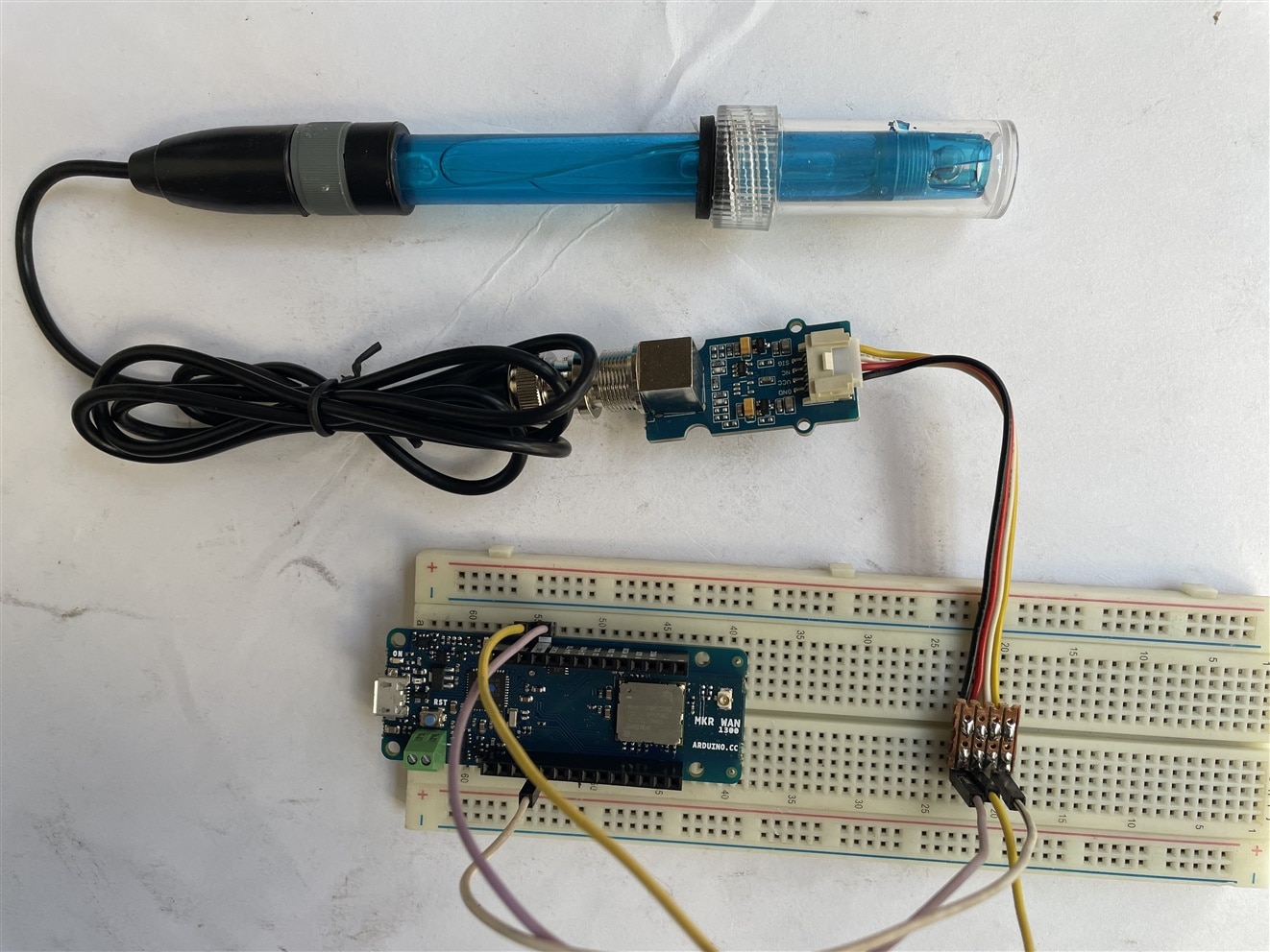
If you are using the waterproof version of the DS18B20, connect Red stripe to 5V, Black connects to ground and Yellow Stripe is data that goes to digital pin 2 on arduino. You still need to connect a 4.7K pullup resistor from data to 5V.
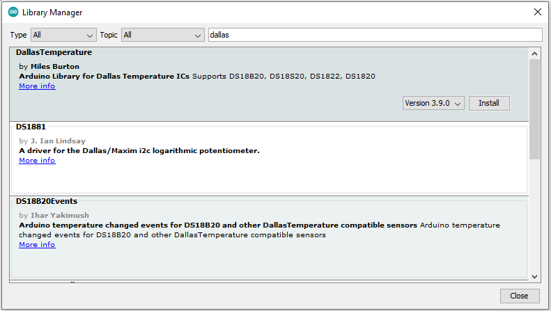
Installing Library
The Dallas 1-Wire protocol is somewhat complex, and requires a bunch of code to parse out the communication. To hide away this unnecessary complexity we will install Dallas Temperature so that we can issue simple commands to get temperature readings from the sensor. This library also requires the OneWire Library.
1. Open your Arduino IDE and go to Sketch > Include Library > Manage Libraries. The Library Manager should open.
2. Type “OneWire” in the search box and install the OneWire library by Paul Stoffregen.

3. Then, search for “Dallas” and install the Dallas Temperature library by Miles Burton.
Uploading the Code
From the File of Arduino IDE and go to Examples > DallasTemperature > Tester. The example code should open.
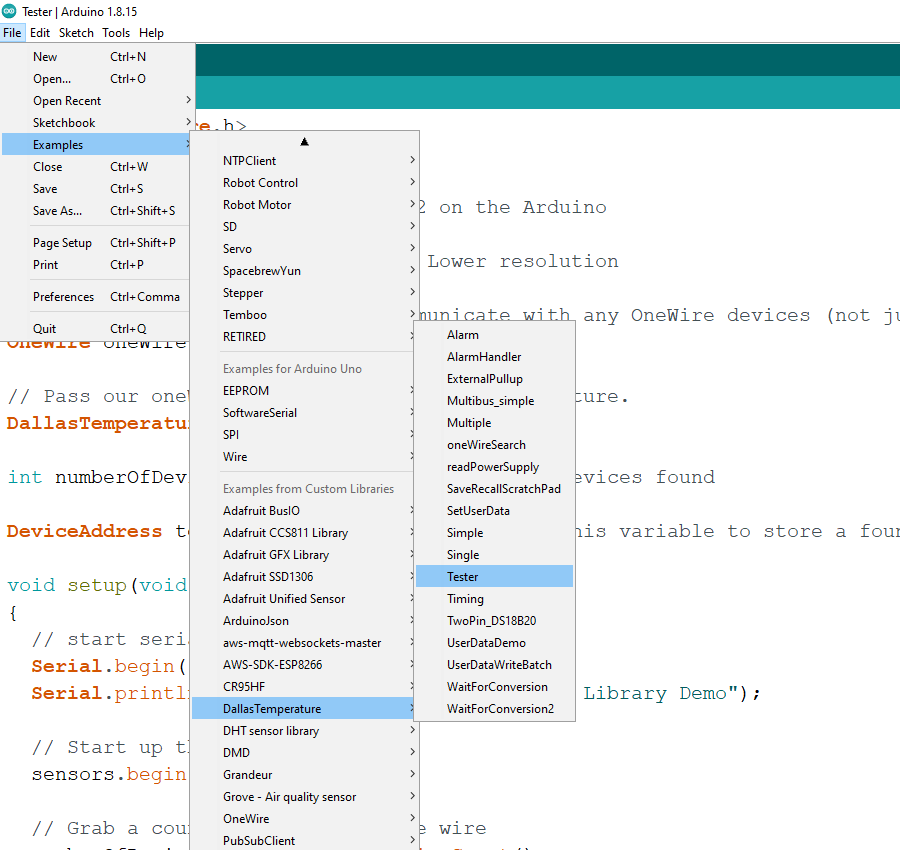
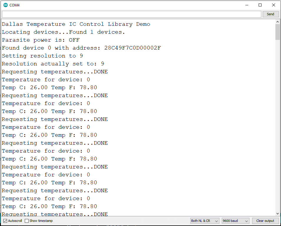
2. Upload the code to your board and observe the result from the serial monitor
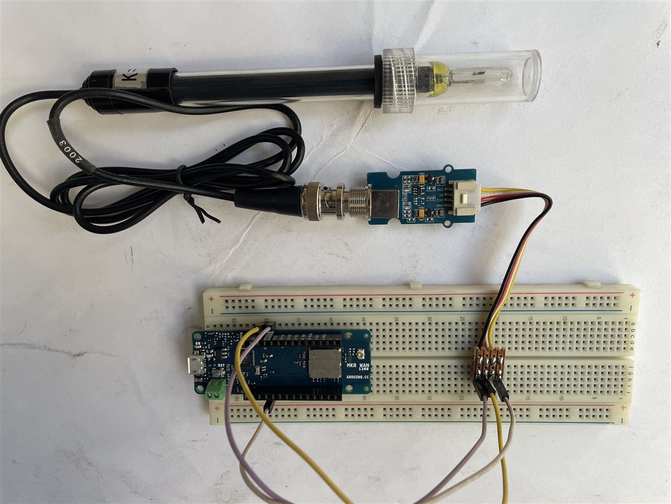
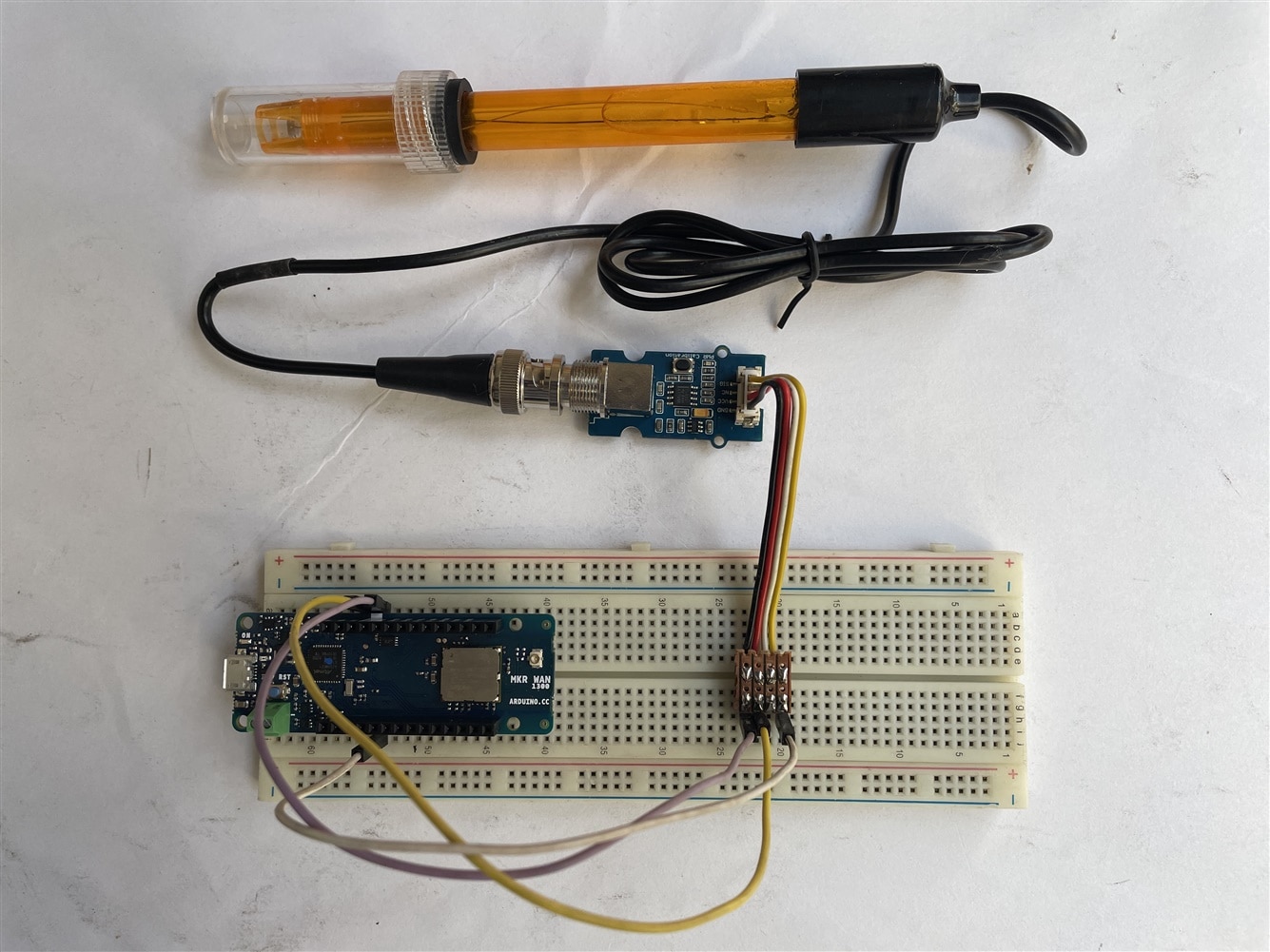
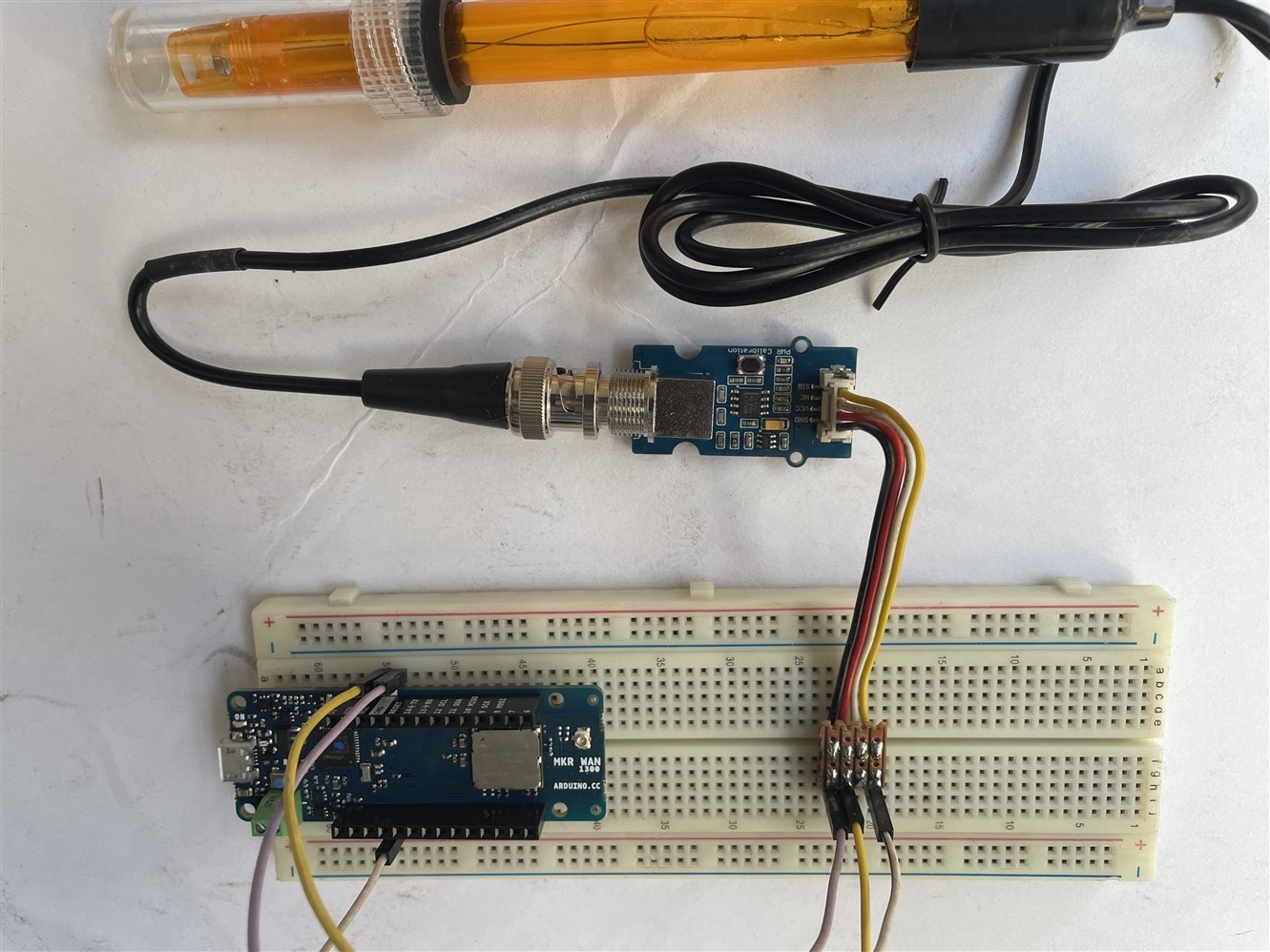
PH Sensor Interfacing
The Grove PH sensor provides analog data. So we need to connect the data pin of the sensor to any Arduino analog pin.
The pH electrode is a passive sensor and does not need any excitation voltage or current. The source impedance of a pH probe is very high because the thin glass bulb has a large resistance that is typically in the range of 10 MΩ to 1000 MΩ. The Seeed Studio’s Grove pH sensor board utlizes an OPA333 Operational Amplifier from TI, which has very low noise, and almost zero drift over temperature.
When the electrode tip is submerged in the fluid solution, the pH electrode produces a voltage output that is linear across a certain range. An ideal pH sensor produces zero voltage at a pH value of 7, and a positive voltage (a few hundred millivolts) when pH value go down, and a negative voltage when pH value go up, caused by the hydrogen irons forming at the outside (and inside) of the membrane glass tip of the pH electrode when the membrane comes into contact with solution.
The Seeed Studio ph sensor board provides a 1.8v reference voltage through a XC6206 voltage regulator, this reference voltage is used to “float” the input by 1.8v above the input reading from the electrode so that the negative voltage when pH value is above 7 can be represented as a voltage below 1.8v, and the positive voltage when the pH value is below 7 can be represented as a voltage above 1.8v. This makes it possible for reading the electrode reading through Analog-to-Digital (ADC) converter of an Arduino because an ADC can’t read negative voltage.
/*
  # This sample code is used to test the pH meter V1.1.
  # Editor : YouYou
  # Date   : 2014.06.23
  # Ver    : 1.1
  # Product: analog pH meter
  # SKU    : SEN0161
*/
#define SensorPin A2            //pH meter Analog output to Arduino Analog Input 0
#define Offset 41.02740741      //deviation compensate
#define LED 13
#define samplingInterval 20
#define printInterval 800
#define ArrayLenth  40    //times of collection
#define uart  Serial
int pHArray[ArrayLenth];   //Store the average value of the sensor feedback
int pHArrayIndex = 0;
void setup(void)
{
  pinMode(LED, OUTPUT);
  uart.begin(9600);
  uart.println("pH meter experiment!");    //Test the uart monitor
}
void loop(void)
{
  static unsigned long samplingTime = millis();
  static unsigned long printTime = millis();
  static float pHValue, voltage;
  if (millis() - samplingTime > samplingInterval)
  {
    pHArray[pHArrayIndex++] = analogRead(SensorPin);
    if (pHArrayIndex == ArrayLenth)pHArrayIndex = 0;
    voltage = avergearray(pHArray, ArrayLenth) * 5.0 / 1024;
    pHValue = -19.18518519 * voltage + Offset;
    samplingTime = millis();
  }
  if (millis() - printTime > printInterval)  //Every 800 milliseconds, print a numerical, convert the state of the LED indicator
  {
    uart.print("Voltage:");
    uart.print(voltage, 2);
    uart.print("    pH value: ");
    uart.println(pHValue, 2);
    digitalWrite(LED, digitalRead(LED) ^ 1);
    printTime = millis();
  }
}
double avergearray(int* arr, int number) {
  int i;
  int max, min;
  double avg;
  long amount = 0;
  if (number <= 0) {
    uart.println("Error number for the array to avraging!/n");
    return 0;
  }
  if (number < 5) { //less than 5, calculated directly statistics
    for (i = 0; i < number; i++) {
      amount += arr[i];
    }
    avg = amount / number;
    return avg;
  } else {
    if (arr[0] < arr[1]) {
      min = arr[0]; max = arr[1];
    }
    else {
      min = arr[1]; max = arr[0];
    }
    for (i = 2; i < number; i++) {
      if (arr[i] < min) {
        amount += min;      //arr<min
        min = arr[i];
      } else {
        if (arr[i] > max) {
          amount += max;  //arr>max
          max = arr[i];
        } else {
          amount += arr[i]; //min<=arr<=max
        }
      }//if
    }//for
    avg = (double)amount / (number - 2);
  }//if
  return avg;
}
As we already used DS18B20 1-wire Digital Thermometer so we will use that data for this purpose also.
Here is the example code based on DFRobot_EC_Test.ino with DS18B20 digital thermometer for temperature compensation calculation. I assume you already download and install OneWire and DallasTemperature Arduino libraries using Library Manager before compiling the code.

For successful compilation, you need to download and install DFRobot_EC library from here.
/*
 * file DFRobot_EC.ino
 * @ https://github.com/DFRobot/DFRobot_EC
 *
 * This is the sample code for Gravity: Analog Electrical Conductivity Sensor / Meter Kit V2 (K=1.0), SKU: DFR0300.
 * In order to guarantee precision, a temperature sensor such as DS18B20 is needed, to execute automatic temperature compensation.
 * You can send commands in the serial monitor to execute the calibration.
 * Serial Commands:
 *   enterec -> enter the calibration mode
 *   calec -> calibrate with the standard buffer solution, two buffer solutions(1413us/cm and 12.88ms/cm) will be automaticlly recognized
 *   exitec -> save the calibrated parameters and exit from calibration mode
 *
 * Copyright   [DFRobot](http://www.dfrobot.com), 2018
 * Copyright   GNU Lesser General Public License
 *
 * version  V1.0
 * date  2018-03-21
 */

#include <DFRobot_EC.h>
#include <EEPROM.h>
#include <OneWire.h>
#include <DallasTemperature.h>

#define EC_PIN A1         // Using A1 as analog input for EC electrode
#define SENSING_INTERVAL 1000

#if ARDUINO_ARCH_STM32    // for STM32 with 12-bit ADC

#define ADC_REF 3300
#define ADC_STEPS 4096.0
#define TEMP_PIN PB9      // Using pin PB9 as temperature sensor input

#else                     // For AVR Adrduinos with 10-bit ADC

#define ADC_REF 5000
#define ADC_STEPS 1024.0
#define TEMP_PIN 3        // Using pin 3 as temperature sensor input

#endif

DFRobot_EC ec;
OneWire oneWire(TEMP_PIN);
DallasTemperature ds18b20(&oneWire);

void setup() {
  Serial.begin(115200);
  ec.begin();
  ds18b20.begin();
#if ARDUINO_ARCH_STM32
  analogReadResolution(12);
#endif
}

void loop() {
  static unsigned long timer = millis();
  float voltage;
  float temperature;

  if(millis() - timer > SENSING_INTERVAL) {
    timer = millis();
    voltage = analogRead(EC_PIN) / ADC_STEPS * ADC_REF;
    ds18b20.requestTemperatures();                     // send command to get temperaure reading
    temperature = ds18b20.getTempCByIndex(0);          // reading temp in celsius
    float ecValue = ec.readEC(voltage,temperature);    // convert voltage to EC with temperature compensation
    Serial.print("temperature:");
    Serial.print(temperature,1);
    Serial.print(" C, EC:");
    Serial.print(ecValue,2);
    Serial.println("ms/cm");
  }
  ec.calibration(voltage,temperature);
}
More details are here.
ORP Sensor Interfacing
ORP (Oxidation-Reduction Potential) is a measure of the ability of oxidation and reduction of aqueous solution, characterization of oxidizing or reducing the relative degree. Unlike a pH measurement that follows a logarithmic curve and therefore requires more calibration adjustments, ORP follows a linear relationship and does not need instrument adjustment as much as it needs electrode maintenance. ORP has proven to be a reliable method of measuring water quality and provides the operator with a single value of measurement regardless of which product, commodity, operation, treatment or sanitizer is used, and regardless of varying field conditions or method by which chemical is applied.
Connect analog data out pin of the sensor to the Arduino A2 pin and upload the following code.
#define VOLTAGE 5.00    //system voltage
#define OFFSET 0        //zero drift voltage
#define LED 13         //operating instructions

double orpValue;

#define ArrayLenth  40    //times of collection
#define orpPin 2         //orp meter output,connect to Arduino controller ADC pin

int orpArray[ArrayLenth];
int orpArrayIndex=0;

double avergearray(int* arr, int number){
  int i;
  int max,min;
  double avg;
  long amount=0;
  if(number<=0){
    printf("Error number for the array to avraging!/n");
    return 0;
  }
  if(number<5){   //less than 5, calculated directly statistics
    for(i=0;i<number;i++){
      amount+=arr[i];
    }
    avg = amount/number;
    return avg;
  }else{
    if(arr[0]<arr[1]){
      min = arr[0];max=arr[1];
    }
    else{
      min=arr[1];max=arr[0];
    }
    for(i=2;i<number;i++){
      if(arr[i]<min){
        amount+=min;        //arr<min
        min=arr[i];
      }else {
        if(arr[i]>max){
          amount+=max;    //arr>max
          max=arr[i];
        }else{
          amount+=arr[i]; //min<=arr<=max
        }
      }//if
    }//for
    avg = (double)amount/(number-2);
  }//if
  return avg;
}


void setup(void) {
  Serial.begin(9600);
  pinMode(LED,OUTPUT);
}

void loop(void) {
  static unsigned long orpTimer=millis();   //analog sampling interval
  static unsigned long printTime=millis();
  if(millis() >= orpTimer)
  {
    orpTimer=millis()+20;
    orpArray[orpArrayIndex++]=analogRead(orpPin);    //read an analog value every 20ms
    if (orpArrayIndex==ArrayLenth) {
      orpArrayIndex=0;
    }
    orpValue=((30*(double)VOLTAGE*1000)-(75*avergearray(orpArray, ArrayLenth)*VOLTAGE*1000/1024))/75-OFFSET;   //convert the analog value to orp according the circuit
  }
  if(millis() >= printTime)   //Every 800 milliseconds, print a numerical, convert the state of the LED indicator
  {
    printTime=millis()+800;
    Serial.print("ORP: ");
    Serial.print((int)orpValue);
        Serial.println("mV");
        digitalWrite(LED,1-digitalRead(LED));
  }
}
Observe the result to the serial monitor.