The Light Up Your Life is a design challenge for creating RGB LED based projects using Würth Electronics RGB LEDs.
I am glad to take part in this challenge and creating a project based on RGB LEDs provided by Wurth electronics.
Participants are required to post at least 5 blog post to complete the challenge successfully and here I am to do that.
- Introduction to the Challenge and PCB design
- First steps with PCB
- Programming the LEDs
- Machine Learning model with LEDs
- Challenges Final blog
The official challenge kit contains some six different kinds of LEDs. These are RGB LEDs connected to the SoC module or microcontroller.
Protocol
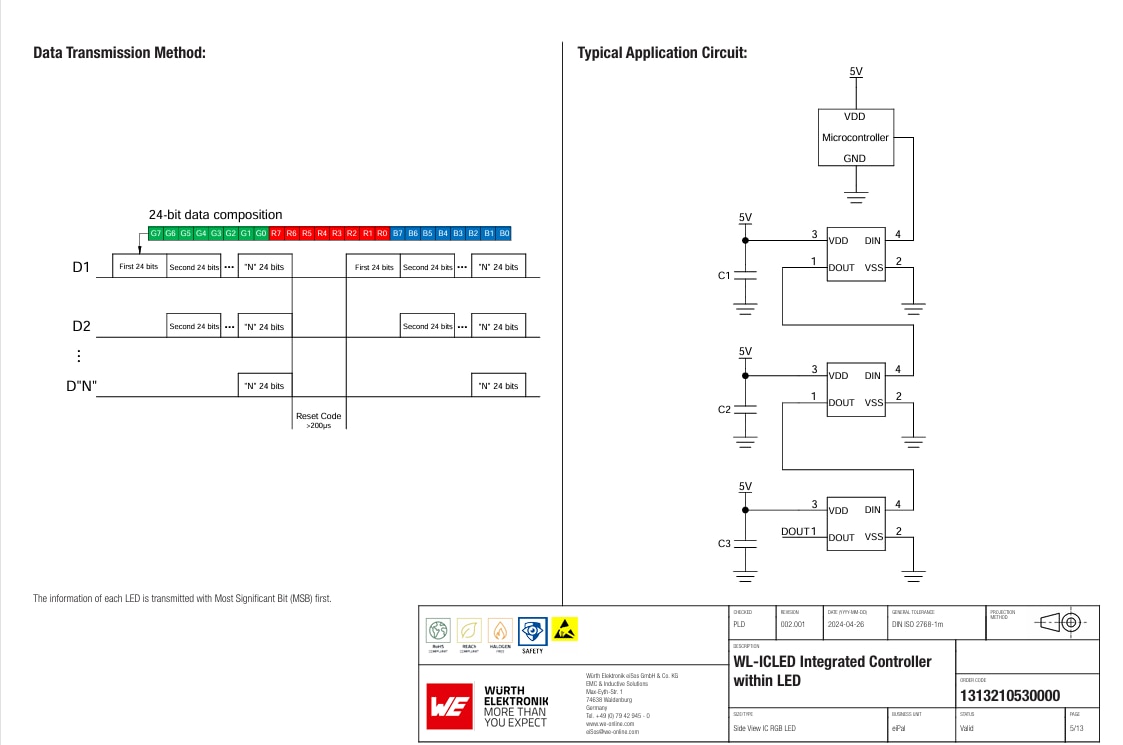
The microcontroller can then generate appropriate PWM signal to create color as required. These LEDs are connected in daisy-chain method to generate color values.
The color of each LED is represented with 8-bit value for each R-G-B channel. Hence, a total of 2^24 colors can be represented. The following image from one of the LEDs datasheets demonstrates how these LEDs can be connected in series and the data format to generate required color value. The first LEDs DOUT is connected to the next ones DIN pin. This way the internal chip of the first LED can transfer the next bytes of incoming color values to the next LEDs in series in the daisy chain method.
As soon as there is a RESET signal, the next incoming data for color values from the microcontroller will start from the first LED in the series.
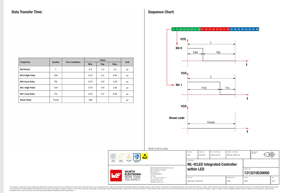
The timings of these LEDs are also important to understand. The following figure explains it visually. The code 0 and code 1 is represented with different kinds of PWM signals. The total wavelength remains the same that is approx. 1.2 us. But the duty cycle changes if the code is 0 or it is 1. For the reset signal though, the period is approx. 200 us.
Calculating parameters for design using datasheet
One important aspect to design a circuit or even PCB is to understand the power requirements (mainly current and voltage) of the final design and specifically of number of these LEDs connected in daisy chain method on a GPIO pin. It is also important to understand the number of LEDs in the design in order to know the overall power requirements of the circuit.
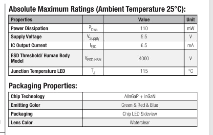
Würth Elektronik provides this power ratings into their datasheet. The following image from one of the datasheets of their LEDs is an example tobe considered. These are the absolute maximum ratings for the LED. To calculate the maximum current that a number of LEDs will require we can use the following table.
As per the table, each of this LED requires 6.5 mA to operate. Technically, as there are three LEDs in one we need to calculate the current accordingly.
So, if I am using three LEDs of this kind, it will require approximately 60 mA to operate. This will help me to decide weather a perticular GPIO is able to handle this current or not.
6.5 x 3 x 3 = 59 mA.
Each one of these LEDs needs decoupling capacitor that is required to filter the incoming power supply ripples. Normally and for most LEDs from Würth would need 100nF capacitor of X7R gradient rating.
Würth Elektronik has different kinds of LEDs in programmable series. For this challenge, there are some interesting LEDs that are different from standard programmable LEDs. They use different programming interface, or they have difference in hardware pins that are available.
One of the issues with these programmable LEDs is that they if they are connected in series (daisy chain method) then if one of the LEDs is not working properly or has malfunctioned then none of the next LEDs will work. This is because they are internally connected, and data will not be transmitted to the next LEDs. To solve such problems, Würth Elektronik provides an LED that can skip single LED if it is not working.

Another example is using different interfacing protocol than standard PWM protocols that LEDs use as explained above. In this LEDs use two pins that is one for Data and another for clock signals.
The following figure shows the timing diagram of the LED that has clock and data lines.