


There is an extensive step-by-step tutorial series on getting started with the FRDM-KV31FFRDM-KV31F Development Platform here
FRDM-KV31F|Freedom Development Platform|Kinetis MCU|NXP
Following through the steps and installing all the software took a couple of hours on a very fast PC - lots of steps and lots of software. Here are some of the software packages that are part of the process:
Kinetis SDK 1.3.0 Mainline - Windows.exe (Kinetis Software Development Kit - 312 MB)
kinetis-design-studio_3.2.0.exe (Kinnetis Design Studio - 701MB)
Eclipse add-on to add Kinetis SDK V2.x Project Wizard.zip (Elcipse upgrade for the Software Development Kit - 243 KB)
KinetisMotorSuite.exe (Kinetis Motor Control Suite - 120 MB)
KSDK-Project-Generator.zip (Kinetis Software Development Kit Project Generator - 32 MB)
Additionally, some of these packages need to be upgraded immediately through an online process.
I was trying for a vanilla default installation using all the default options, but it did not go smoothly for me.
Before installation I had spent a lot of time to collect all the info I could find on all the hardware and software involved in the kit. One issue I ran into was documentation of the motor. After lots of searching I found several different datasheets on the motor, but none of them had any detail on what the 8 wires were coming out of the motor. Freescale had lots of documentation on how a 3 phase brushless DC motor works, but again, almost no information on wiring this particular motor up. They seem to use this same motor for many of their demo applications for other products, so eventually I came across a note that indicated it didn't matter which phase was connected to which terminal. This still did not help identify which 3 wires to use. There are 2 white wires, 2 blue wires, 2 green wires, a red wire and a black wire. I noticed that one each of white, blue and green wires were slightly heavier gauge so I am assuming these are the main motor phase wires. I gather from some of the docs I found that the other wires are probably 3 Hall effect sensor outputs (white, blue and green) and the red and black wires are 5 volt power and ground. I came across some images that have the red wire going to the ground pin and the black wire going to the power pin as well as some images where they are going to the phase sensor pins, so I still have no idea which wires do what. I am not at all comfortable connecting this motor up without better documentation - I doubt Hall effect sensors (assuming that is what some wires go to) will be happy with 24VDC on their outputs. Likewise if they had their power pins reversed, they probably wouldn't be in great shape. Anyway, after several hours of scouring the web, I am stuck with guessing which 3 wires to use and leaving the rest disconnected. If anyone has a wiring diagram for this motor, I would dearly like to see it.
I have purchased a 150W DC-DC converter to supply 24 VDC from a 12 VDC battery:
It seems to work well, but I will know more once I get the motor working. It will require a 12 V battery capable of putting out at least 10A.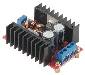
The 4800 mAH Li-Ion battery I have may not be quite up to it, but I want to test the actual requirements in my application before writing it off.
Here is my motor test setup showing a 700 Watt MFJ power supply substituting for the battery: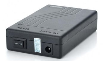

Okay, back to software installation woes. After 7 hours of struggling with it, I still have nothing working. The installation tutorial seemed to go okay - a bit fitfully, since the video was not clear enough to read any of the text on the screen in the video. Some straight forward steps were left as an exercise for the viewer, but resulted in discrepancies with the video, so had to be redone or corrected.
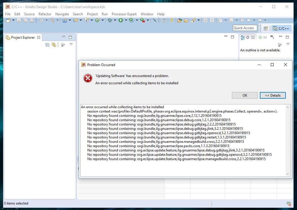
Part of the process involved upgrading the Kinetis Design Studio, which could not complete because of missing repository files. I could not figure out how to correct this so I proceeded, hoping the upgrade was not crucial. Unfortunately, it probably was needed. Here is the error:
When I got to the end of the process there were some exercises to try loading demo programs, but none of the examples were available beyond the driver libs. I didn't see anything that looked like an example with this motor control system.
Update: I did finally get the examples sorted out and running, but no luck with the Motor Suite.
So I skipped on to try the Kinetis Motor Suite. I gather the MCU module comes loaded with motor demo firmware, but after sorting out and configuring the serial port, the Motor Suite could not connect to the MCU module because the .out or .elf file in the Motor Suite did not match what was in the MCU module. Here is the error:
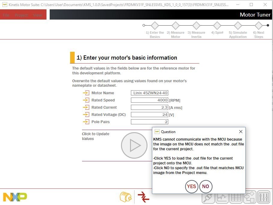
I could not figure out how to get the .elf files to match, indeed I could not get the Motor Suite to find the right directory, possibly because there wasn't a .elf file in the right directory. This may all be due to the failure in upgrading, but whatever the reason, I have not been able to get past this failure to connect yet.
I have not been able to find any description of the pre-loaded demo firmware in the MCU module beyond that it will blink red and blue when powered up. (which it does) Nor can I find the source code for this demo.
One thing I noticed is that the MCU needs to be connected to a PC to run its demo program - simply connecting it to a USB power supply does nothing, not even an LED lights up. I will have to change this as my application is stand-alone - no PC in the front yard.
I really want to get on with building my system, but I have to get this basic stuff working. It is clear from the gigabytes of software I have installed and the many steps involved in software project development that I have a massive learning curve ahead of me. So far it is pretty frustrating, but hopefully I will start making better progress shortly.
The Kinetis Motor Suite (in the Project menu) has a menu option to "Show Path Selections".
This reveals that "Kinetis Design Studio: Not Selected"
The Project menu also has an option to "Select Paths" with a drop down to select path for "Kinetis Design Studio" which brings up a standard "Browse For Folder" window.
Selecting the directory where KDS installed pops up this error:
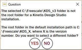
I have tried every level of directory and this same error always pops up. The directory in the first line of the error message is the one I selected on this attempt and it is the directory where the install program installed KDS by default. The Kinetis Motor Suite just does not recognize the install directory of the Kinetis Design Suite or the location of the .elf file.
I have not been able to get any answers from Kinetis, but one note on one of their forums indicated that KMS does not work with KDS3.2.
I will try earlier versions this weekend to see if that works. 30 hours on this issue so far is putting a serious crimp in my development schedule.
.........
After installing KDS3.0 things started working a little better. I did have to set up the directory where KDS3.0 was installed, but then I could get the COM port set up and connected. The motor wouldn't do anything at this point, but eventually I figured out the little fault indicator was trying to tell me the DC input was over voltage - even though it was set to exactly 24 VDC.
I had to turn the voltage down all the way to about 12 VDC to get the fault to disappear. It gives an under voltage fault below 11 VDC and an over voltage fault above 14 VDC. I'm sure this can be altered as the motor and drive module are rated to run at 24 VDC.
With the input voltage at 12 volts I was able to get the motor running. There is a lot of flexibility in the motor suite that is going to take some experimentation to learn, but I will start with a short video in my next blog showing the motor running.
Relevant Links
The full set of Clear Walk project blogs can be found here:
Top Comments