


Table of Contents
Challenges
The UT325F Protocol
The UNI-T device has a Universal Serial Bus (USB) converter to a Universal Asynchronous Receiver Transmitter (UART). This is based on the known CHXXX series converter. This was a challenge since there is no information about how the temperature data is transmitted, despite the device having a Bluetooth App for android and Microsoft Windows application for data recording. Furthermore, the data observed during transmission with default configuration to the user interface has the following composition

The  control variable has the value of 0xAA and acts as start frame flag,
 are unknown meaning variables at the development moment, the
  are the Temperature variables in little endian format for IEEE 754 float representation,
 represents which probes are connected from bytes 1 to 4, and
  is a 16-bit check sum code with big-endian encoding. Once the protocol is identified, the connection to the Python CLI is sufficient to decode the 56-byte frame using the code below,
import serial
import struct
import time

SERIAL_PORT = '/dev/ttyS20'
BAUD_RATE = 115200
TIMEOUT = 1
FRAME_LEN = 56

def compute_checksum(data):
    """Calculate big-endian 16-bit checksum"""
    total = sum(data) & 0xFFFF   # Máscara para 16 bits
    return total.to_bytes(2, 'big')

def parse_temperature(frame):
    """
    Extract 4 Float numbers in little endian format
    Initial index is equal to 5
    """
    start = 5
    floats = []
    for i in range(4):
        b = frame[start + i*4 : start + i*4 + 4]
        if len(b) == 4:
            val = struct.unpack('<f', b)[0]
            floats.append(val)
        else:
            floats.append(None)
    return floats

def parse_connected(frame):
    """
    Verify that a Thermocouple N has a connected sensor
    Each bytes illustrates that the channel has a connected thermocouple if
    the code is 0x00, or 0x30 if not
    """
    start = 21
    channels = []
    for i in range(4):
        v = frame[21 + i]
        if v == 0x00:
            channels.append(True)
        else:
            channels.append(False)
    return channels

def read_and_validate(ser):
    buffer = bytearray()
    while True:
        byte = ser.read(1)
        if not byte:
            continue
        buffer.append(byte[0])

        if len(buffer) >= 2 and buffer[-2] == 0xAA and buffer[-1] == 0x55:
            while len(buffer) < FRAME_LEN:
                b = ser.read(1)
                if not b:
                    break
                buffer.append(b[0])
            if len(buffer) >= FRAME_LEN:
                frame = buffer[-FRAME_LEN:]
                data_part = frame[:-2]
                recv_checksum = frame[-2:]
                calc_checksum = compute_checksum(data_part)
                if recv_checksum == calc_checksum:
                    return frame
                else:
                    print("Checksum inválido, descartando trama")
                    buffer.pop(0)
            else:
                buffer.clear()
        else:
            if len(buffer) > FRAME_LEN * 2:
                buffer = buffer[-FRAME_LEN:]


def main():
    try:
        ser = serial.Serial(SERIAL_PORT, BAUD_RATE, timeout=TIMEOUT)
        while True:
            frame = read_and_validate(ser)
            if frame:
                temps = parse_temperature(frame)
                valid = parse_connected(frame)
                print("Temperature:", temps)
                print("Connected Sensors:", valid)
    except serial.SerialException as e:
        print(f"Serial por error: {e}")
    except KeyboardInterrupt:
        print("\nExecution stopped by the user")
    finally:
        if 'ser' in locals() and ser.is_open:
            ser.close()

if __name__ == "__main__":
    main()
The protocol decoding were sufficient despite the unknow variables, but a new challenge arose since the Arduino UNO Q Linux image has no the CH340 converter driver.
The CHxxx series driver
Despite the Linux image has no native driver for the USB-UART CH340 device, it is possible to compile and install the drivers for the used target. The WCHSoftGroup share the source code to compile and install the driver in a platform which the driver is unavailable. You only need to download the GitHub repository, change directory to ./driver folder and execute the commands
sudo apt-get update
sudo make
sudo make install
If you do not have the development tools you must execute the following command before make commands
sudo apt-get install build-essential
I used picocom tool communication link testing, but the Arduino Linux image has minicom preinstalled. You will get a ttyCH340USBx device in the system using this driver. You must establish communication with the target device using a 115200 bauds per second (bps) communication velocity. Remember! The data is transmitted in HEX values, consequently, your terminal must be configured in that encoding to ensure operation. Once the data is available, the python script must be able to capture data and share with the network in order to monitor and control the cooling system. But after a huge amount of tries, the Arduino App Lab could not connect with the serial port despite the correct enumeration. This broughs the las significative challenge.
Data access
In order to solve the limited access of Arduino App Lab to the port, a background perspective is used. There is a background Python script that takes the data from the serial port and shares it using JavaScript Object Notation (JSON) format by a socket using a REmote DIctionary Server (Redis) service. Redis storage data on memory with a NoSQL philosophy, it is used to quick response data cache for temperature sharing in the network. It is required to install and start a Redis server with the commands below to implement a Redis node.
sudo apt-get install redis-server
sudo systemctl start redis-server
When the Redis is available in the following script run in background to take a sample and upload to memory service to be consumed by other application in the network.
import serial
import struct
import time
import redis
import json

FRAME_LEN = 56

def compute_checksum(data):
	"""Calculate big-endian 16-bit checksum"""
	total = sum(data) & 0xFFFF
	return total.to_bytes(2, 'big')

def parse_temperature(frame):
	"""
	Extract 4 Float numbers in little endian format
	Initial index is equal to 5
	"""
	start = 5
	floats = []
	for i in range(4):
		b = frame[start + i*4 : start + i*4 + 4]
		if len(b) == 4:
			val = struct.unpack('<f', b)[0]  # little-endian
			floats.append(val)
		else:
			floats.append(None)
	return floats

def parse_connected(frame):
	"""
	Verify that a Thermocouple N has a connected sensor
	Each bytes illustrates that the channel has a connected thermocouple if
	the code is 0x00, or 0x30 if not
	"""
	start = 21
	channels = []
	for i in range(4):
		v = frame[21 + i]
		if v == 0x00:
			channels.append(True)
		else:
			channels.append(False)
	return channels

def read_and_validate(ser):
    """Lee datos del puerto serie, busca la trama válida y la retorna."""
    buffer = bytearray()
    while True:
        byte = ser.read(1)
        if not byte:
            continue
        buffer.append(byte[0])

        if len(buffer) >= 2 and buffer[-2] == 0xAA and buffer[-1] == 0x55:
            while len(buffer) < FRAME_LEN:
                b = ser.read(1)
                if not b:
                    break
                buffer.append(b[0])
            if len(buffer) >= FRAME_LEN:
                frame = buffer[-FRAME_LEN:]
                data_part = frame[:-2]
                recv_checksum = frame[-2:]
                calc_checksum = compute_checksum(data_part)
                if recv_checksum == calc_checksum:
                    return frame
                else:
                    print("Checksum inválido, descartando trama")
                    buffer.pop(0)
            else:
                buffer.clear()
        else:
            if len(buffer) > FRAME_LEN * 2:
                buffer = buffer[-FRAME_LEN:]


def data2dict(temps, sensors):
	data = {}
	for k in range(4):
		data.update({f"T{k}": (temps[k], sensors[k])})
	return data

def main():
	try:
		ser = serial.Serial('/dev/ttyCH341USB0', 115200, timeout=1)
		rShared = redis.Redis(host='localhost', port=6379, db=0)
		if rShared.ping():
			print("Connected")
		while True:
			ser.reset_input_buffer()
			frame = read_and_validate(ser)
			if frame:
				temps = parse_temperature(frame)
				valid = parse_connected(frame)
				dData = data2dict(temps, valid)

				if rShared.ping():
        				rShared.lpush('ss', json.dumps(dData))
				time.sleep(1)
	except serial.SerialException as e:
		print(f"Serial por error: {e}")
	except KeyboardInterrupt:
		print("\nExecution stopped by the user")
	finally:
		if 'ser' in locals() and ser.is_open:
			ser.close()

if __name__ == "__main__":
	main()
Setup
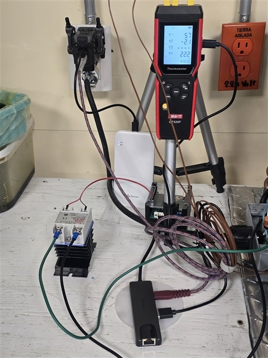
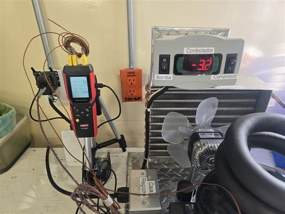
The physical system consists of a compressor system, but this is instrumented and controlled by the Arduino UNO Q. The whole system has a UT325F Thermometer as a verification display since the data is transmitted to the Linux interface by the serial port. There are three probes connected, one for the glycol solution that is in the interchange chamber, another probe in the water inside the container immersed in the glycol and one not processed probe more for the ambient temperature. There is an additional free channel for future purposes. The processed probes consist of the use of thermowell with thermal paste to improve thermal transfer, this isolates the sensor terminal from harsh environments that will be used like acid electrolytes.
For power conditioning, the microcontroller interface activates an AC solid state relay (SSR) for fan and compressor loads to AC line. This allows remote control and monitoring using a WiFi connection. Adding a wireless connection to the platform brings an additional secure layer since the cooling system, which could generate Hydrogen and other gases, or had a considerable temperature gap to damage the container inside, is isolated from the operator.
Using the WebUI brick it is possible to access the data available in the Arduino by network and take control of the pinout according to the implemented code. For the recent testing, I used a pattern controller to check the action control and verify the rules to implement. The project is described below,
import numpy as np
from arduino.app_utils import *
from arduino.app_bricks.dbstorage_tsstore import TimeSeriesStore
from arduino.app_bricks.web_ui import WebUI
import redis
import json

# Global state
led_is_on = False
temp_value = np.zeros((4,1))
probe_valid = np.zeros((4,1))
tmp ="OK"
db = TimeSeriesStore()
t1_data = ""
t2_data = ""
t3_data = ""
t4_data = ""

def get_led_status():
    """Get current LED status for API."""
    return {
        "led_is_on": led_is_on,
        "status_text": tmp,
        "t1_status": t1_data,
        "t2_status": t2_data,
        "t3_status": t3_data,
        "t4_status": t4_data,
    }

def toggle_led_state(client, data):
    """Toggle the LED state when receiving socket message."""
    global led_is_on
    led_is_on = not led_is_on

    # Call a function in the sketch, using the Bridge helper library, to control the state of the LED connected to the microcontroller.
    # This performs a RPC call and allows the Python code and the Sketch code to communicate.
    Bridge.call("set_led_state", led_is_on)

    # Send updated status to all connected clients
    ui.send_message('led_status_update', get_led_status())

def on_get_initial_state(client, data):
    """Handle client request for initial LED state."""
    ui.send_message('led_status_update', get_led_status(), client)

# Initialize WebUI
ui = WebUI()

# Handle socket messages (like in Code Scanner example)
ui.on_message('toggle_led', toggle_led_state)
ui.on_message('get_initial_state', on_get_initial_state)

def get_events():
    global tmp
    global t1_data
    global t2_data
    global t3_data
    global t4_data
    try:
        rShared = redis.Redis(host='192.168.0.123', port=6379, db=0)
        #print('Connected')
        if rShared.ping() and rShared.llen('ss') > 0:
            dInput = json.loads(rShared.lpop('ss').decode('utf-8'))
            tmp = f'{dInput["T0"][0]:.1f}'
            t1_data = f'{dInput["T0"][0]:.1f}'
            t2_data = f'{dInput["T1"][0]:.1f}'
            t3_data = f'{dInput["T2"][0]:.1f}'
            t4_data = f'{dInput["T3"][0]:.1f}'
            ui.send_message('led_status_update', get_led_status())
    except redis.exceptions.ConnectionError as e:
        print(f'{e}')

# Start the application
App.run(user_loop=get_events)
const ledButton = document.getElementById('led-button');
const ledText = document.getElementById('led-text');
const t1Data = document.getElementById('T1-data');
const t2Data = document.getElementById('T2-data');
const t3Data = document.getElementById('T3-data');
const t4Data = document.getElementById('T4-data');
let errorContainer;

/*
 * Socket initialization. We need it to communicate with the server
 */
const socket = io(`http://${window.location.host}`); // Initialize socket.io connection

// Start the application
document.addEventListener('DOMContentLoaded', () => {
    errorContainer = document.getElementById('error-container');
    initSocketIO();

    // Add event listener to LED button
    ledButton.addEventListener('click', handleLedClick);
});

function initSocketIO() {
    socket.on('connect', () => {
        // Request initial LED state
        socket.emit('get_initial_state', {});
        if (errorContainer) {
            errorContainer.style.display = 'none';
            errorContainer.textContent = '';
        }
    });

    socket.on('led_status_update', (message) => {
        updateLedStatus(message);
    });

    socket.on('disconnect', () => {
        if (errorContainer) {
            errorContainer.textContent = 'Connection to the board lost. Please check the connection.';
            errorContainer.style.display = 'block';
        }
    });
}

/*
 * These functions are used to update the UI based on the server's LED status.
 */

// Function to update LED status in the UI
function updateLedStatus(status) {
    const isOn = status.led_is_on;
    const msg = status.status_text.toString();

    // Update LED button appearance and text
    ledButton.className = isOn ? 'led-on' : 'led-off';
    ledText.textContent = msg;//isOn ? 'LED IS ON' : 'LED IS OFF';
    t1Data.textContent = status.t1_status.toString();
    t2Data.textContent = status.t2_status.toString();
    t3Data.textContent = status.t3_status.toString();
    t4Data.textContent = status.t4_status.toString();
}

// Function to handle LED button click
function handleLedClick() {
    // Send toggle message to server via socket
    socket.emit('toggle_led', {});
}
<!DOCTYPE html>
<html lang="en">
<head>
    <meta charset="UTF-8">
    <meta name="viewport" content="width=device-width, initial-scale=1.0">
    <title>Linux Blink</title>
    <link rel="icon" type="image/png" href="./img/favicon.png">

    <link rel="stylesheet" type="text/css" href="style.css">
</head>
<body>
    <div>
        <div class="header">
            <h1 class="arduino-text">Linux Blink</h1>
            <img class="arduino-logo" src="./img/RGB-Arduino-Logo_Color Inline Loop.svg" alt="Arduino Logo">
        </div>


        <div class="container">
            <!-- LED Button with integrated text -->
            <div class="led-container">
                <button id="led-button" class="led-off">
                    <span id="led-text">LED IS OFF</span>
                </button>
            </div>

            <!-- Instruction Text -->
            <p class="instruction-text">Click to control board's LED 👆</p>

            <!-- Data Text -->
            <p id="T1-data" class="data-text">
              DEMO DATA
            </p>
            <p id="T2-data" class="data-text">
              DEMO DATA
            </p>
            <p id="T3-data" class="data-text">
              DEMO DATA
            </p>
            <p id="T4-data" class="data-text">
              DEMO DATA
            </p>

            <!-- Error message container -->
            <div id="error-container" class="error-message" style="display: none;"></div>
        </div>
    </div>

    <script src="libs/socket.io.min.js"></script>
    <script src="app.js"></script>
</body>
</html>
#include <Arduino_RouterBridge.h>

void setup() {
    pinMode(D12, OUTPUT);
    digitalWrite(D12, HIGH);

    Bridge.begin();
    Bridge.provide("set_led_state", set_led_state);
}

void loop() {}

void set_led_state(bool state) {
    digitalWrite(D12, state ? LOW : HIGH);
}
This project is based on the Linux Blink example project. All those components required on the desktop version were added to the embedded version with compatibility and new compiling drivers for the additional hardware.
| {gallery}Setup |
|---|
 |
 |
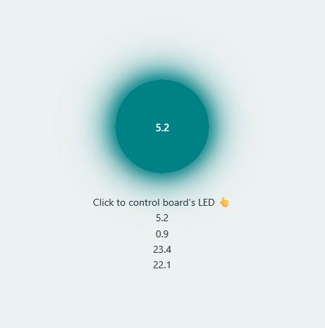 |
Figure 1. System setup in operation
Results
After the setup is operative, there was a initial test using an arbitrary temperature. The objetive is maintain a constant temperature for the container inside the glycol. The glycol thermal chraracteristics guarantee a good thermal transfer between the container and the interchange chamber. Despite the thermal variations as a consequence of the chamber energy losses, the water in the container must be constant as possible.

Figure 2. Temperature control operation
The system has an inherent thermal inertia, despite the objective temperature in the glycol was -2 °C, with an compressor activation on -0.5 °C, the system overcome this limits according this feature. But this test brough interesting behavior according the figure above. The orange curve represents the glycol interchange chamber; the blue one shows the temperature in the water for the container inside the glycol. The compressor operation maintains a glycol temperature oscillation about 8 °C while the water maintains an oscillation of 0.5°C. These variations occur since the actual controller is of ON/OFF controller type. Despite the oscillation is huge in glycol, the container has a small one, which is our interest in the chemical cell. For the future, we must quantify chamber mass lost using the humidity measures and add new instruments and actuators like pumps to compensate matter losses or electrolyte features such as pH.
Acknowledgements
We would like to thank the sponsors and the Element14 community for their support. We are working continuously to develop a useful and secure equipment for the ESIQIE and materials science laboratories. I am improving the system and I hope to show you the final product soon.


