


1 Full System Architecture
1.1 Low-cost distributed IMU motion sensing over industrial CAN bus, edge data forwarding to PC-side LabVIEW visualization & AI monitoring.
The schedule is delayed totally since I misuse Arduino CAN library which support MCP2501 over SPI. I have to rebuild sustomized CAN library by GPIO simulation, although the Arduino Uno Q support CAN natively, but the port is not wiring out. The STM32U support high speed CANFD, which is perfect fit for MAX33040 shield.
Fully custom CAN receiver stack on Uno Q demonstrate embedded low-level CAN protocol implementation, end-to-end industrial sensing pipeline for manufacturing line monitoring challenge.
1.2 Hardware Signal Flow
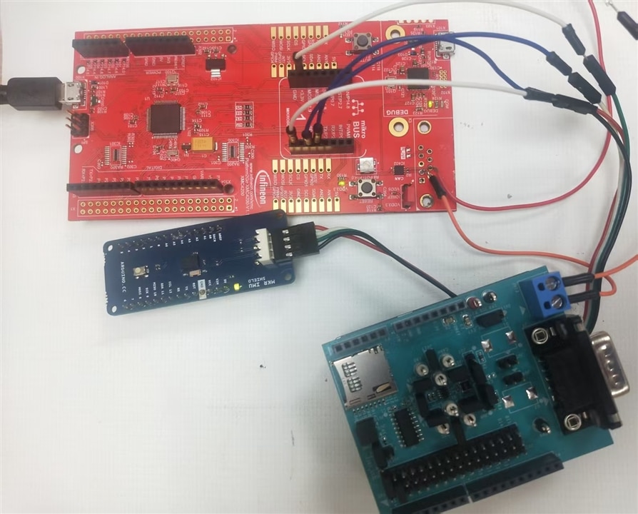
| Component | Function |
|---|---|
| Platform2Go 4200 | Transmit node: read MKR IMU, package IMU X/Y/Z data into CAN frames |
| MKR IMU Shield | Motion sensor source (Accel X,Y,Z float values) |
| CAN Twisted Pair Cable | Differential CAN bus wiring, 120Ω termination resistors at bus ends |
| Arduino Uno Q | Central receive node, custom MAX33040 CAN receiver stack |
| MAX33040 CAN Transceiver Shield | Physical layer CAN bus interface for Uno Q |
| USB Cables | Platform2Go 4200 power/debug; Uno Q USB to PC for VISA |
| NI-VISA Driver + LabVIEW | PC visualization, data analysis, AI detection |
- Platform2Go 4200 CAN_H -> MAX33040 CAN_H
- Platform2Go 4200 CAN_L -> MAX33040 CAN_L
- Common GND connection between all CAN nodes
- 120Ω resistor across CAN_H/CAN_L at Platform2Go 4200 and Uno Q bus endpoints over MAX33040 Shiel
2 Transmit Side – Platform2Go 4200 Workflow
Platform2Go 4200 polls IMU via I2C, reads raw acceleration X/Y/Z , converts raw integer register values to engineering float units
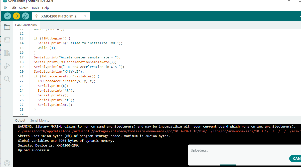
#include <CAN.h>
#include <MKRIMU.h>

float x, y, z;

void setup() {
  Serial.begin(9600);
  while (!Serial);

  if (!IMU.begin()) {
    Serial.println("Failed to initialize IMU!");
    while (1);
  }
  Serial.print("Accelerometer sample rate = ");
  Serial.print(IMU.accelerationSampleRate());
  Serial.println(" Hz and Acceleration in G's ");
  Serial.println("X\tY\tZ");
  if (IMU.accelerationAvailable()) {
    IMU.readAcceleration(x, y, z);
    Serial.print(x);
    Serial.print('\t');
    Serial.print(y);
    Serial.print('\t');
    Serial.println(z);
  }

  Serial.println("CAN Sender");

  // start the CAN bus at 500 kbps
  if (!CAN.begin(500E3)) {
    Serial.println("Starting CAN failed!");
    while (1);
  }

}

void loop() {
  // send packet: id is 11 bits, packet can contain up to 8 bytes of data
  Serial.print("Sending packet ... ");

  CAN.beginPacket(0x12);
  CAN.write('h');
  CAN.write('e');
  CAN.write('l');
  CAN.write('l');
  CAN.write('o');
  /************`
    if (IMU.accelerationAvailable()) {
    IMU.readAcceleration(x, y, z);
    CAN.write(&x,4);
    //Serial.print('\t');
    CAN.write(y);
    //Serial.print('\t');
    CAN.write(z);
  }*/
  CAN.endPacket();

  int packetSize = CAN.parsePacket();
  if (packetSize) {
    // received a packet
    Serial.print("Received ");
  }

  Serial.println("done");

}
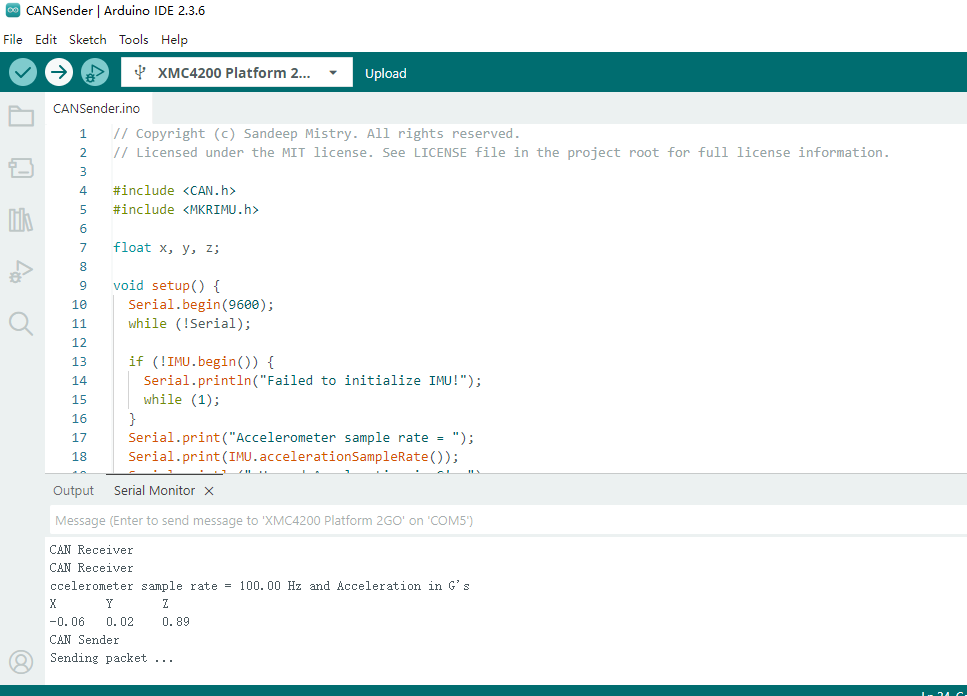
The reading for x-y-z is output
3 Receive Side – Arduino Uno Q + MAX33040 Custom Self-Built CAN Library
3.1 Hardware Control Logic
- MAX33040D4 STB pin set HIGH on startup to exit low-power standby
- UART hardware pins D0(RX)/D1(TX) connect directly to MAX33040 differential CAN physical layer
3.2 The library with GPIOpin simulation for CAN
#include "MAX33040_CAN.h"

// ============================================
// ============================================
static MAX33040_CAN* _instance = NULL;


// ============================================
MAX33040_CAN::MAX33040_CAN(uint8_t txPin, uint8_t rxPin)
    : _txPin(txPin)
    , _rxPin(rxPin)
    , _speed(DEFAULT_CAN_SPEED)
    , _txState(CAN_STATE_IDLE)
    , _txActive(false)
    , _rxState(CAN_STATE_IDLE)
    , _rxReady(false)
    , _rxQueueHead(0)
    , _rxQueueTail(0)
    , _errorCount(0) {
}


// ============================================
bool MAX33040_CAN::begin(uint32_t speed) {
    _speed = speed;

    // 初始化引脚
    pinMode(_txPin, OUTPUT);
    digitalWrite(_txPin, HIGH);  // CAN recessive

    pinMode(_rxPin, INPUT);


    _instance = this;

    _txState = CAN_STATE_IDLE;
    _txActive = false;
    _rxState = CAN_STATE_IDLE;
    _rxReady = false;
    _rxQueueHead = 0;
    _rxQueueTail = 0;
    _errorCount = 0;

    attachInterrupt(CAN_RX_INT, []() {
        if (_instance) {
            _instance->interruptHandler();
        }
    }, CHANGE);

    return true;
}


// ============================================
uint8_t MAX33040_CAN::calcCRC(const CANFrame& frame) {

    uint16_t crc = 0;


    for (int i = 10; i >= 0; i--) {
        bool bit = (frame.id >> i) & 1;
        bool newBit = bit ^ ((crc >> 14) & 1);
        crc = (crc << 1) & 0x7FFF;
        if (newBit) {
            crc ^= 0x4599;
        }
    }

    for (int i = 3; i >= 0; i--) {
        bool bit = (frame.dlc >> i) & 1;
        bool newBit = bit ^ ((crc >> 14) & 1);
        crc = (crc << 1) & 0x7FFF;
        if (newBit) {
            crc ^= 0x4599;
        }
    }


    for (uint8_t j = 0; j < frame.dlc; j++) {
        for (int i = 7; i >= 0; i--) {
            bool bit = (frame.data[j] >> i) & 1;
            bool newBit = bit ^ ((crc >> 14) & 1);
            crc = (crc << 1) & 0x7FFF;
            if (newBit) {
                crc ^= 0x4599;
            }
        }
    }

    return (uint8_t)(crc >> 7);
}


// ============================================
void MAX33040_CAN::txIdle() {
    digitalWrite(_txPin, HIGH);  // Recessive
}

void MAX33040_CAN::txDominant() {
    digitalWrite(_txPin, LOW);  // Dominant
}


void MAX33040_CAN::writeBit(bool bit) {
    if (bit) {
        txIdle();
    } else {
        txDominant();
    }
}


// ============================================
bool MAX33040_CAN::sendFrame(const CANFrame& frame) {
    if (_txActive) {
        return false;
    }


    _txFrame = frame;
    if (_txFrame.dlc > 8) _txFrame.dlc = 8;

    _txState = CAN_STATE_RECV_SOF;
    _txActive = true;
    _txBitCount = 0;
    _txByteIndex = 0;
    _txBitIndex = 0;
    _txStartTime = micros();

    txDominant();

    return true;
}


// ============================================
bool MAX33040_CAN::sendAccelData(const AccelData& accel) {
    CANFrame frame;

    frame.id = CAN_ID_ACCEL_DATA;
    frame.dlc = 12;


    uint8_t* px = (uint8_t*)&accel.x;
    uint8_t* py = (uint8_t*)&accel.y;
    uint8_t* pz = (uint8_t*)&accel.z;


    for (int i = 0; i < 4; i++) {
        frame.data[i] = px[i];
    }

    for (int i = 0; i < 4; i++) {
        frame.data[4 + i] = py[i];
    }

    for (int i = 0; i < 4; i++) {
        frame.data[8 + i] = pz[i];
    }

    frame.dlc = 12;

    return sendFrame(frame);
}


// ============================================
void MAX33040_CAN::updateTxState() {
    if (!_txActive) return;

    uint32_t bitTime = 1000000UL / _speed;
    uint32_t now = micros();
    uint32_t elapsed = now - _txStartTime;

    uint8_t bitNum = elapsed / bitTime;

    while (bitNum > _txBitCount) {

        bool txBit = HIGH;

        switch (_txState) {
            case CAN_STATE_RECV_SOF: {
                _txState = CAN_STATE_RECV_ID;
                _txBitCount++;
                _txBitIndex = 10;
                break;
            }

            case CAN_STATE_RECV_ID: {
                txBit = (_txFrame.id >> _txBitIndex) & 1;
                if (_txBitIndex == 0) {
                    _txState = CAN_STATE_RECV_RTR;
                }
                _txBitIndex--;
                break;
            }

            case CAN_STATE_RECV_RTR: {

                _txState = CAN_STATE_RECV_DLC;
                _txBitIndex = 3;
                break;
            }

            case CAN_STATE_RECV_DLC: {
                txBit = (_txFrame.dlc >> _txBitIndex) & 1;
                if (_txBitIndex == 0) {
                    _txState = CAN_STATE_RECV_DATA;
                    _txByteIndex = 0;
                    _txBitIndex = 7;
                } else {
                    _txBitIndex--;
                }
                break;
            }

            case CAN_STATE_RECV_DATA: {
                if (_txByteIndex < _txFrame.dlc) {
                    txBit = (_txFrame.data[_txByteIndex] >> _txBitIndex) & 1;
                    if (_txBitIndex == 0) {
                        _txByteIndex++;
                        _txBitIndex = 7;
                        if (_txByteIndex >= _txFrame.dlc) {
                            _txState = CAN_STATE_RECV_CRC;
                            _txBitIndex = 14;
                            _crcAccum = calcCRC(_txFrame);
                        }
                    } else {
                        _txBitIndex--;
                    }
                }
                break;
            }

            case CAN_STATE_RECV_CRC: {
                txBit = (_crcAccum >> _txBitIndex) & 1;
                if (_txBitIndex == 0) {
                    _txState = CAN_STATE_RECV_ACK;
                } else {
                    _txBitIndex--;
                }
                break;
            }

            case CAN_STATE_RECV_ACK: {

                _txState = CAN_STATE_RECV_EOF;
                _txBitCount = 0;
                break;
            }

            case CAN_STATE_RECV_EOF: {

                _txState = CAN_STATE_IDLE;
                _txActive = false;
                txIdle();
                return;
            }

            default:
                _txActive = false;
                txIdle();
                return;
        }


        writeBit(txBit);
        _txBitCount++;
    }
}

// ============================================
void MAX33040_CAN::interruptHandler() {
    static uint32_t lastTime = 0;
    static uint8_t lastState = HIGH;

    uint32_t now = micros();
    uint8_t currentState = digitalRead(_rxPin);

    if (currentState == lastState) return;

    uint32_t delta = now - lastTime;
    lastTime = now;
    lastState = currentState;

    uint32_t bitTime = 1000000UL / _speed;


    uint8_t bits = delta / bitTime;
    if (bits == 0) bits = 1;

    bool bit = (currentState == HIGH);
    static uint8_t bitBuffer[32];
    static uint8_t bitIndex = 0;
    static bool inFrame = false;

    if (!inFrame && !bit && _rxState == CAN_STATE_IDLE) {
        inFrame = true;
        _rxState = CAN_STATE_RECV_ID;
        _rxBitCount = 1;
        _rxByteIndex = 0;
        _rxBitIndex = 10;
        bitIndex = 0;
        _crcAccum = 0;
        memset(&_rxFrame, 0, sizeof(_rxFrame));
        return;
    }

    if (!inFrame) return;


    for (uint8_t i = 0; i < min(bits, (uint8_t)8); i++) {
        bitBuffer[bitIndex++] = bit;

        if (bitIndex >= 11 + 1 + 4 + 8 * 8 + 15 + 2 + 7) {

            parseReceivedFrame(bitBuffer);
            inFrame = false;
            _rxState = CAN_STATE_IDLE;
            return;
        }
    }
}


void MAX33040_CAN::parseReceivedFrame(uint8_t* buffer) {
    uint8_t idx = 0;

    idx++;


    _rxFrame.id = 0;
    for (int i = 10; i >= 0; i--) {
        _rxFrame.id |= (buffer[idx++] & 1) << i;
    }


    idx++;

    _rxFrame.dlc = 0;
    for (int i = 3; i >= 0; i--) {
        _rxFrame.dlc |= (buffer[idx++] & 1) << i;
    }
    if (_rxFrame.dlc > 8) _rxFrame.dlc = 8;


    for (uint8_t b = 0; b < _rxFrame.dlc; b++) {
        _rxFrame.data[b] = 0;
        for (int i = 7; i >= 0; i--) {
            _rxFrame.data[b] |= (buffer[idx++] & 1) << i;
        }
    }


    _rxQueue[_rxQueueHead] = _rxFrame;
    _rxQueueHead = (_rxQueueHead + 1) % 2;
    _rxReady = true;
}


bool MAX33040_CAN::available() {
    return _rxReady;
}


bool MAX33040_CAN::readFrame(CANFrame& frame) {
    if (!_rxReady) return false;

    frame = _rxQueue[_rxQueueTail];
    _rxQueueTail = (_rxQueueTail + 1) % 2;

    if (_rxQueueHead == _rxQueueTail) {
        _rxReady = false;
    }

    return true;
}

bool MAX33040_CAN::getAccelData(AccelData& accel) {
    CANFrame frame;

    if (!readFrame(frame)) {
        return false;
    }

    if (frame.dlc < 12) {
        _errorCount++;
        return false;
    }

    uint8_t* px = (uint8_t*)&accel.x;
    uint8_t* py = (uint8_t*)&accel.y;
    uint8_t* pz = (uint8_t*)&accel.z;

    for (int i = 0; i < 4; i++) {
        px[i] = frame.data[i];
        py[i] = frame.data[4 + i];
        pz[i] = frame.data[8 + i];
    }

    return true;
}
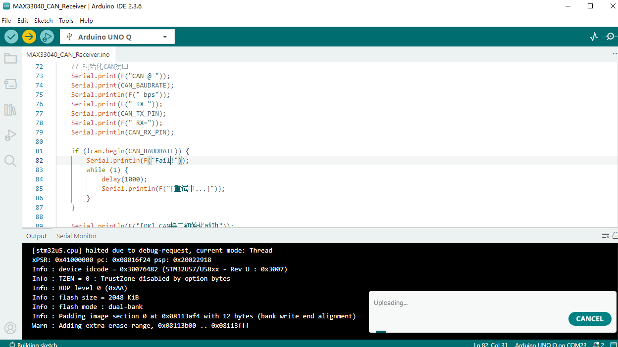
Flash the code in Arduino IDE and receive the x-y-z data in float type,first wait for the CAN initiation.
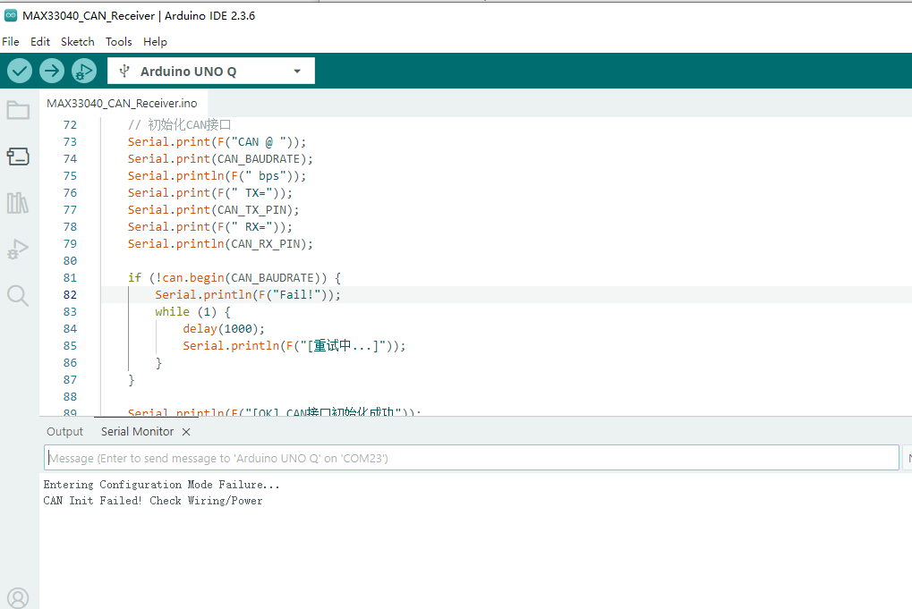
The Arduino UNO Q send data received from CAN bus over SERIAL port, this is for LABVIEW VISA port to get data. The operation loop,
- Initialize custom CAN library + MAX33040
- Continuous poll for incoming CAN frames
- If valid IMU CAN ID detected: unpack all X/Y/Z float values
- Format serial CSV string, transmit over Uno Q USB UART
There are NI LINX support best fit for this project, but only support Arduino Uno, so it can not be used for the moment.
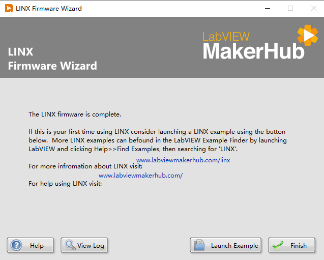
4 LabVIEW NI-VISA Serial Read & Full VI Pipeline
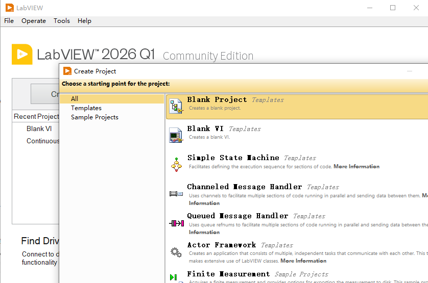
Create one blank project ,
4.1 LabVIEW Pre-Requisites
- NI-VISA driver installed
- Close Arduino IDE Serial Monitor before running LabVIEW (prevents COM port lock conflict)
- Record Uno Q assigned COM port number in Windows Device Manager, COM 23 for this case,
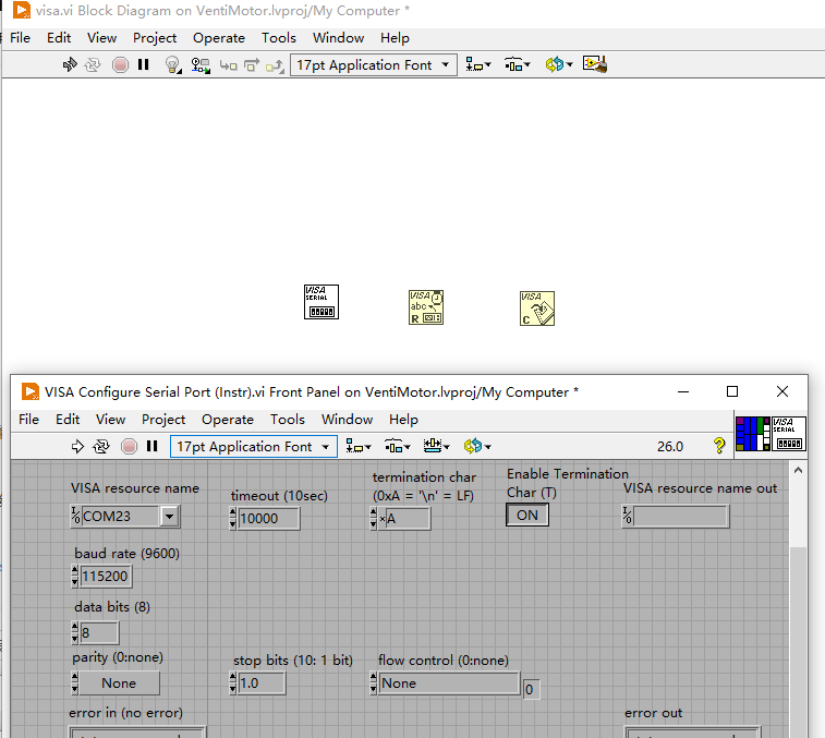
4.2 Complete VI Modular Design
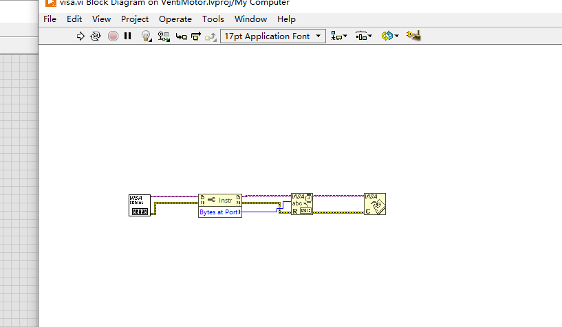
- VISA Serial Initialization
- Front Panel Controls: COM Port String Input, Baud Rate (115200 match Uno Q serial), Parity=None, Data Bits=8, Stop Bits=1
- Block Diagram: VISA Configure Serial Port → VISA Flush Buffer (clear stale CAN/UART garbage data)
- Error cluster wired sequentially for full fault tracking
While Loop Real-Time VISA Read Core
- VISA Read function (read buffer length = 128 bytes, enough for full IMU serial frame)
- Conditional structure: Only process data if received byte count > 0
- String cleaning subVI: Strip
\r\nline terminators
IMU Serial String Parsing (Extract X/Y/Z Floats)
- String Split by comma delimiter → string array,ax,ay,az,
- Array index validation (array length =7 before conversion, reject broken partial frames)
- String-to-number conversion for 3 float outputs: ax,ay,az
Graphical Visualization & AI Anomaly Detection
- Real-Time Waveform Chart: 6 trace curves (Accel X/Y/Z ), scrolling live motion plot
- Python AI integration (advanced)
5 Summary
The Labview is perfect for industrial line supervision and the CAN is typical choice for industrial communication over Vehicles. All the kits is enough for this design, but misuse of port and library put off the progress.
This is how the project proposed and how to implement the idea. There are still more to improve for the Industrial line in operation.