element14 Community
element14 Community
    Register Log In
  • Site
  • Search
  • Log In Register
  • Community Hub
    Community Hub
    • What's New on element14
    • Feedback and Support
    • Benefits of Membership
    • Personal Blogs
    • Members Area
    • Achievement Levels
  • Learn
    Learn
    • Ask an Expert
    • eBooks
    • element14 presents
    • Learning Center
    • Tech Spotlight
    • STEM Academy
    • Webinars, Training and Events
    • Learning Groups
  • Technologies
    Technologies
    • 3D Printing
    • FPGA
    • Industrial Automation
    • Internet of Things
    • Power & Energy
    • Sensors
    • Technology Groups
  • Challenges & Projects
    Challenges & Projects
    • Design Challenges
    • element14 presents Projects
    • Project14
    • Arduino Projects
    • Raspberry Pi Projects
    • Project Groups
  • Products
    Products
    • Arduino
    • Avnet & Tria Boards Community
    • Dev Tools
    • Manufacturers
    • Multicomp Pro
    • Product Groups
    • Raspberry Pi
    • RoadTests & Reviews
  • About Us
    About the element14 Community
  • Store
    Store
    • Visit Your Store
    • Choose another store...
      • Europe
      •  Austria (German)
      •  Belgium (Dutch, French)
      •  Bulgaria (Bulgarian)
      •  Czech Republic (Czech)
      •  Denmark (Danish)
      •  Estonia (Estonian)
      •  Finland (Finnish)
      •  France (French)
      •  Germany (German)
      •  Hungary (Hungarian)
      •  Ireland
      •  Israel
      •  Italy (Italian)
      •  Latvia (Latvian)
      •  
      •  Lithuania (Lithuanian)
      •  Netherlands (Dutch)
      •  Norway (Norwegian)
      •  Poland (Polish)
      •  Portugal (Portuguese)
      •  Romania (Romanian)
      •  Russia (Russian)
      •  Slovakia (Slovak)
      •  Slovenia (Slovenian)
      •  Spain (Spanish)
      •  Sweden (Swedish)
      •  Switzerland(German, French)
      •  Turkey (Turkish)
      •  United Kingdom
      • Asia Pacific
      •  Australia
      •  China
      •  Hong Kong
      •  India
      •  Japan
      •  Korea (Korean)
      •  Malaysia
      •  New Zealand
      •  Philippines
      •  Singapore
      •  Taiwan
      •  Thailand (Thai)
      •  Vietnam
      • Americas
      •  Brazil (Portuguese)
      •  Canada
      •  Mexico (Spanish)
      •  United States
      Can't find the country/region you're looking for? Visit our export site or find a local distributor.
  • Translate
  • Profile
  • Settings
On the Line
  • Challenges & Projects
  • Design Challenges
  • On the Line
  • More
  • Cancel
On the Line
Forum Smart Ventilation Motor Monitoring System #4 Run with MAX33041ESHLD# on Arduino UNO Q
  • News
  • Projects
  • Forum
  • DC
  • Leaderboard
  • Files
  • Members
  • More
  • Cancel
  • New
Join On the Line to participate - click to join for free!
Actions
  • Share
  • More
  • Cancel
Forum Thread Details
  • Replies 7 replies
  • Subscribers 36 subscribers
  • Views 224 views
  • Users 0 members are here
Related

Smart Ventilation Motor Monitoring System #4 Run with MAX33041ESHLD# on Arduino UNO Q

fyaocn
fyaocn 1 month ago

1 Use  with Arduino Uno Q

1 Hardware Overview MAX33041ESHLD

MAX33041ESHLD is an Arduino/Mbed-compatible CAN physical-layer shield with MAX33041E CAN transceiver + MAX14931 isolated level shifter (1.71V~5.5V I/O). It has configurable onboard 120Ω/60Ω CAN bus termination via jumpers, DB9 and terminal-block CANH/CANL ports, plus configurable TXD/RXD/STBY/SHDN routed via JU1~JU20 jumpers.
Critical: This board only contains CAN PHY chip (no CAN protocol controller). Classic ATmega328P Arduino Uno lacks hardware CAN controller, so an external MCP2515 SPI CAN controller module + MCP_CAN v1.5 library is mandatory for full CAN2.0 protocol communication.

Refer to MAX33041E Shield-Evaluates: MAX33041E , below is MAX33041ESHLD 

image

rear side view

image`

Here is the MAX33041 chip 

image

stack the MAX33041ESHLD with Arduino Uno Q

with JUMPER configuration

Jumper Default Setting Function
JU1 TXD=D1, RXD=D0 PHY TX ← Arduino D1; PHY RX → Arduino D0
JU10 1-2 STBY pin tied to Arduino D6 (LOW=normal CAN, HIGH=sleep)
JU9 1-2 SHDN pin tied to Arduino D7
JU11 2-3 External VDD power; switch to 1-2 to power MAX33041E from Arduino 3.3V
JU7/JU8 2-3 60Ω internal load; set 1-2 for integrated 120Ω CAN bus termination

image

via Arduino Pin

  • MCP2515 SPI to Uno: SCK=D13, MOSI=D11, MISO=D12, CS=D10, INT=D2 (MCP_CAN default pin definition)
  • MAX33041ESHLD Logic Lines:
    • Shield TXD(D1) ← MCP2515 TX output
    • Shield RXD(D0) → MCP2515 RX input
    • Shield STBY(D6)=LOW (permanently enable transceiver working mode)

image

For other part of CAN ,

CAN Bus: Connect MCP2515 CANH/CANL to MAX33041ESHLD CANH/CANL; enable 120Ω termination at bus endpoints via JU7/JU8=1-2.

2 Run the pilot test code

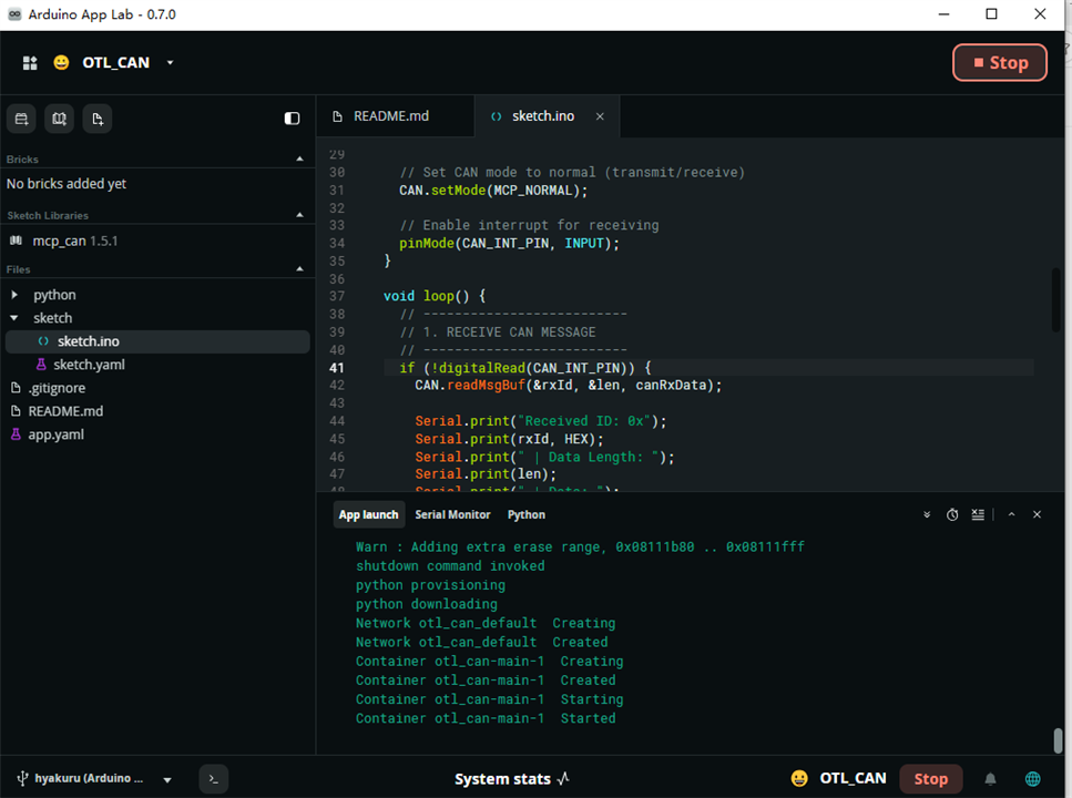
Open the Arduino App LAB and search the board
image

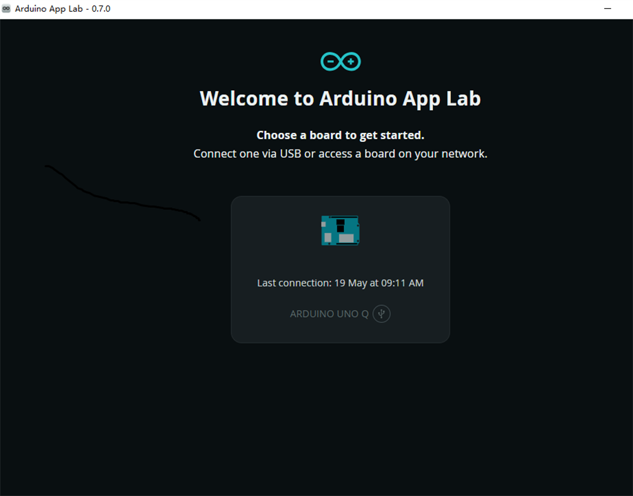
download and install the can library for arduino, refer to GitHub - coryjfowler/MCP_CAN_lib: MCP_CAN Library · GitHub
image

Core API Features for the MCP_CAN lib,

Initialization: CAN.begin(mcp_type, baudrate, crystal) supports 5k~1000k baud @8/16/20MHz MCP2515 clock; after init defaults to loopback mode, use setMode(MCP_NORMAL) to switch to real bus communication.

Receive API readMsgBuf(&id, &len, buf):

  • id & 0x80000000 = true: 29-bit extended CAN ID; else standard 11-bit ID
  • id & 0x40000000 = true: received remote frame
  • Alternative overload readMsgBuf(&id, &ext, &len, buf): ext=1 = extended ID (no remote flag inside ID)

Transmit API:

  • sendMsgBuf(id, len, buf): id|=0x80000000 → extended ID; id|=0x40000000 → remote transmit request
  • sendMsgBuf(id, ext, len, buf): second parameter ext=1 for extended ID
Extra functions:
  • enOneShotTX() / disOneShotTX(): enable/disable single-shot transmit
  • setSleepWakeup(1): open bus-wake interrupt for sleep mode recovery

Here is the  test code

#include <mcp_can.h>
#include <SPI.h>

// Pin definition for MAX33041ESHLD# Shield
#define CAN_CS_PIN 10
#define CAN_INT_PIN 2

// Initialize CAN controller
MCP_CAN CAN(CAN_CS_PIN);

// CAN message buffers
unsigned char canRxData[8];  // Received data
unsigned char canTxData[8] = {0x11, 0x22, 0x33, 0x44, 0x55, 0x66, 0x77, 0x88}; // Send data
long unsigned int rxId;      // Received ID
unsigned char len;           // Data length
unsigned char extFlag = 0;   // 0 = Standard ID (11-bit), 1 = Extended ID (29-bit)

void setup() {
  Serial.begin(115200);
  while (!Serial);

  // Initialize CAN bus: 500kbps baud rate, 8MHz clock (standard)
  if (CAN.begin(MCP_ANY, CAN_500KBPS, MCP_8MHZ) == CAN_OK) {
    Serial.println("CAN Initialized Successfully! (MAX33041E)");
  } else {
    Serial.println("CAN Init Failed! Check Wiring/Power");
    while (1); // Halt if failed
  }

  // Set CAN mode to normal (transmit/receive)
  CAN.setMode(MCP_NORMAL);

  // Enable interrupt for receiving
  pinMode(CAN_INT_PIN, INPUT);
}

void loop() {
  // --------------------------
  // 1. RECEIVE CAN MESSAGE
  // --------------------------
  if (!digitalRead(CAN_INT_PIN)) {
    CAN.readMsgBuf(&rxId, &len, canRxData);

    Serial.print("Received ID: 0x");
    Serial.print(rxId, HEX);
    Serial.print(" | Data Length: ");
    Serial.print(len);
    Serial.print(" | Data: ");
    
    for (int i = 0; i < len; i++) {
      Serial.print(canRxData[i], HEX);
      Serial.print(" ");
    }
    Serial.println();
  }

  // --------------------------
  // 2. SEND CAN MESSAGE (every 1 second)
  // --------------------------
  // Send to ID: 0x123 (standard 11-bit), 8 bytes data
  byte sendStatus = CAN.sendMsgBuf(0x123, 0, 8, canTxData);
  
  if (sendStatus == CAN_OK) {
    Serial.println("Message Sent Successfully!");
  } else {
    Serial.println("Send Failed!");
  }

  delay(1000);
}
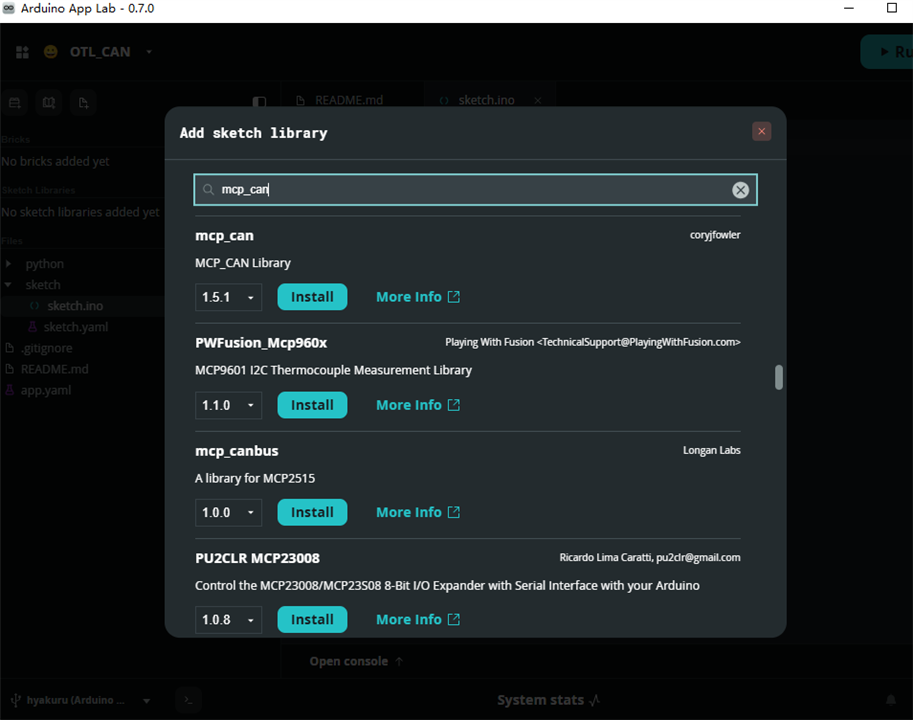
image

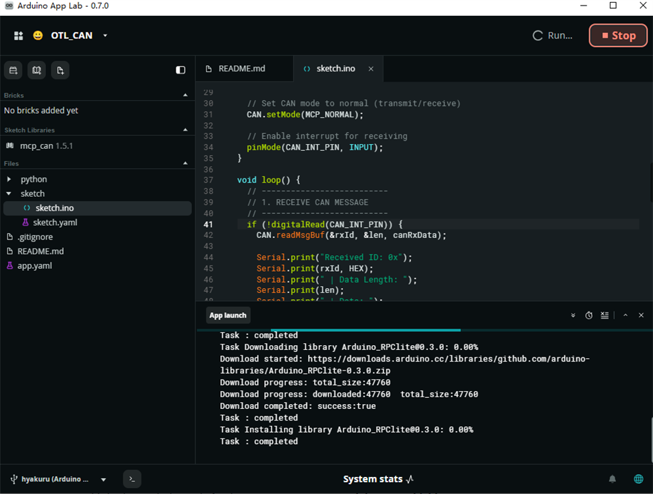
Press run for the progress

image

and here is output from terminal, since this is only one side of CAN transmitter, fail it is right result. Improve later.
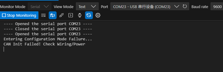
image

Be noted, python is run as well. That is Arduino Uno Q, and how it plays
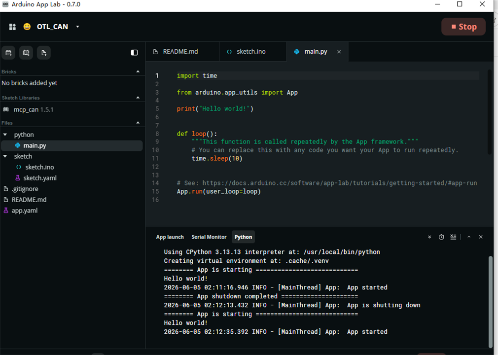
image

3 Summary

Now the CAN transceiver is ready to go,

Next step, get data from sensor data from another CAN terminal .

  • Sign in to reply
  • Cancel

Top Replies

  • saramic
    saramic 1 month ago +1
    amazing - I will definitely use this as a great resource - thanks for writing it up - my only issue is I want to use the LED display on the UNO Q and using it as a hat covers that ️
  • skruglewicz
    skruglewicz 1 month ago +1
    This is fantastic work, fyaocn ! Thank you so much for putting this together—you've honestly saved me a massive amount of time. I’ve been wrestling with this same CAN bus integration on the Arduino UNO…
  • skruglewicz
    skruglewicz 1 month ago +1
    fyaocn said: and here is output from terminal, since this is only one side of CAN transmitter, fail it is right result. Improve later. fyaocn Just interested in your take on WHY the failure
  • saramic
    saramic 1 month ago

    amazing - I will definitely use this as a great resource - thanks for writing it up - my only issue is I want to use the LED display on the UNO Q and using it as a hat covers that

    Face palm️

    • Cancel
    • Vote Up +1 Vote Down
    • Sign in to reply
    • Cancel
  • skruglewicz
    skruglewicz 1 month ago

    This is fantastic work, fyaocn  !

    Thank you so much for putting this together—you've honestly saved me a massive amount of time. I’ve been wrestling with this same CAN bus integration on the Arduino UNO Q with limited success, and your breakdown of the MAX33041ESHLD hardware jumper configurations is a huge win.

    I’m very interested in using your code to help get my own shield connected to my UNO Q. I'm currently working through the CAN bus architecture myself, and I plan to follow the steps you've outlined here to deepen my understanding of the setup.

    I am particularly stuck on implementing a CAN receiver. How are you planning to tackle the receiver side of the integration? I’d love to hear your approach for getting the receiver logic working and how you envision that fitting into the broader system architecture.

    I just published my own forum post for the challenge  Forum 3: UNO Q + MAX33041ESHLD CAN Bus Integration - ILS. it is not working and I'll be updating it as I learn more from your research here on your forum post

    Thanks again for sharing your research—this really helps clear up the hurdles I've been hitting!

    thanks in advance 

    #skruglewicz

    • Cancel
    • Vote Up +1 Vote Down
    • Sign in to reply
    • Cancel
  • skruglewicz
    skruglewicz 1 month ago
    fyaocn said:
    and here is output from terminal, since this is only one side of CAN transmitter, fail it is right result. Improve later.

    fyaocn Just interested in your take on WHY the failure

    • Cancel
    • Vote Up +1 Vote Down
    • Sign in to reply
    • Cancel
  • skruglewicz
    skruglewicz 1 month ago

    Hi Again 

    fyaocn said:
    Critical: This board only contains CAN PHY chip (no CAN protocol controller). Classic ATmega328P Arduino Uno lacks hardware CAN controller, so an external MCP2515 SPI CAN controller module + MCP_CAN v1.5 library is mandatory for full CAN2.0 protocol communication.

    I'm not sure I understand. Why is it critical? and what hardware is missing here?

    • Cancel
    • Vote Up 0 Vote Down
    • Sign in to reply
    • Cancel
  • fyaocn
    fyaocn 1 month ago in reply to skruglewicz

    This mcp can lib use spi.h as well.

    So,spi works in this demo

    I  am on with other side of can and post blog later

    • Cancel
    • Vote Up 0 Vote Down
    • Sign in to reply
    • Cancel
  • skruglewicz
    skruglewicz 1 month ago in reply to fyaocn
    fyaocn said:
    I  am on with other side of can

    UMM ok.. what do you mean "i am on with other side of can"

    • Cancel
    • Vote Up 0 Vote Down
    • Sign in to reply
    • Cancel
  • arvindsa
    arvindsa 1 month ago

    fyaocn  MCP_CAN is for  MCP2515 or MCP25625 which is a CAN Controller which interfaces with the MCU using SPI. But max33041e is a transceiver and we have to use the CAN Controller inside the STM32 of ArduinoQ to get it to work. As per the Arduino Q Pinout: https://docs.arduino.cc/resources/pinouts/ABX00162-full-pinout.pdf  the D4 and D5 pins are the CAN Pins, and as per https://www.analog.com/media/en/technical-documentation/data-sheets/MAX33041ESHLD.pdf there is no SPI pins. Now i am trying to get this working with ArduinoQ

    • Cancel
    • Vote Up 0 Vote Down
    • Sign in to reply
    • Cancel
element14 Community

element14 is the first online community specifically for engineers. Connect with your peers and get expert answers to your questions.

  • Members
  • Learn
  • Technologies
  • Challenges & Projects
  • Products
  • Store
  • About Us
  • Feedback & Support
  • FAQs
  • Terms of Use
  • Privacy Policy
  • Legal and Copyright Notices
  • Sitemap
  • Cookies

An Avnet Company © 2026 Premier Farnell Limited. All Rights Reserved.

Premier Farnell Ltd, registered in England and Wales (no 00876412), registered office: Farnell House, Forge Lane, Leeds LS12 2NE.

Follow element14

  • X
  • Facebook
  • linkedin
  • YouTube