


Introduction
The cooling system is not only temperature dependable, but the system also requires a device that allows temperature reduction in fluids mainly. This device is known as compressor, it takes a refrigerant gas in a closed loop and circulates it throughout a pneumatic circuit. Additional components are necessary in the circuit because compression and decompression can increase or decrease the temperature of the interchange chamber. The challenge here now is how to use a low-level digital signal to activate a high-power AC load. The solution is a solid-state relay (SSR).
| {gallery}Design Platform |
|---|
 |
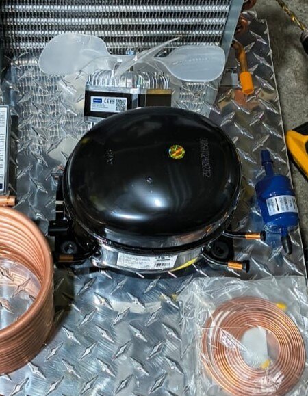 |
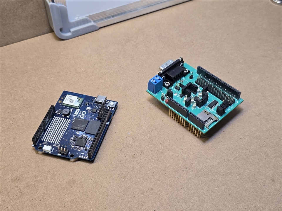
Figure 1. Design platform
Methodology
Why use an SSR compared with an electromechanical relay (EMR)?
The EMR requires a specific power supply such as 5VCD or 12VCD. In the Arduino UNO Q system, the digital terminals are controlled by the microcontroller system. According to the datasheet, some I/O pins are 5VCD tolerant, but they only generate up to 4VCD, which voltage is not sufficient to activate the relay. As you may wonder, is there any option to activate the EMC with lower voltage? There are EMC in the market that activates the coil with 3VCD with a 25Ω internal resistance, consequently, it is possible to use this kind of relays. On the other hand, the I/O has a limit of 20 mA maximum of current to be sourced; the 3VCD@25 Ω consumes 120 mA, this means that the I/O pin of the microcontroller will be damaged operating in these conditions. Additionally, the AC loads could create an electric arc when the load is disconnected from the mechanical switch. This arc could discharge in the control signal and damage all the system, requiring isolation or anti arc PCB for high-current loads.
| {gallery}I/O features |
|---|
 |
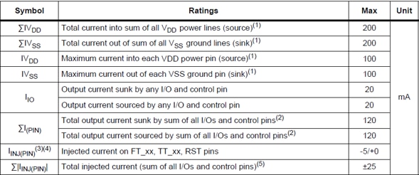 |
Figure 2. Microcontroller I/O characteristics
The assembled compressor has ¼ HP, which it represents a load of 186.5 W for a pure resistive load. But the compressor has additional features like inductive and capacitive behavior. This means that a compressor requires a better switch capacity according to the power factor (PF). I considered a PF=0.5, this means that the current will be about 3A@120VAC. An EMC of 12VCD can handle a load of 10A@125VAC but it requires an additional power supply in the system. In order to minimize the possible arc generation derived of switching and avoiding additional components in the system for power conditioning, an SSR is a better option. The SSR for AC loads has semiconductor elements to reach high commutation frequency and these elements reduce the arc generation risk for the power required in this system. An additional feature is the isolation between control and power stages; it allows easy maintenance for the systems and ensures security.
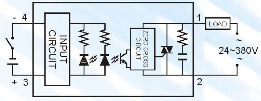
Figure 3. SSR internals (FOTEK SSR Series datasheet)
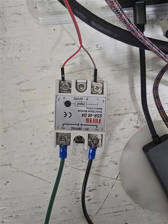
I implemented the example of blink LED using the RPC interface changing the digital pin 12. This perspective was used with the SSR since the example creates a web user interface by WebUI Arduino brick to turn on/turn off the SSR with a 3V3 digital control signal.
| {gallery}SSR test |
|---|
 |
|
|
|
|
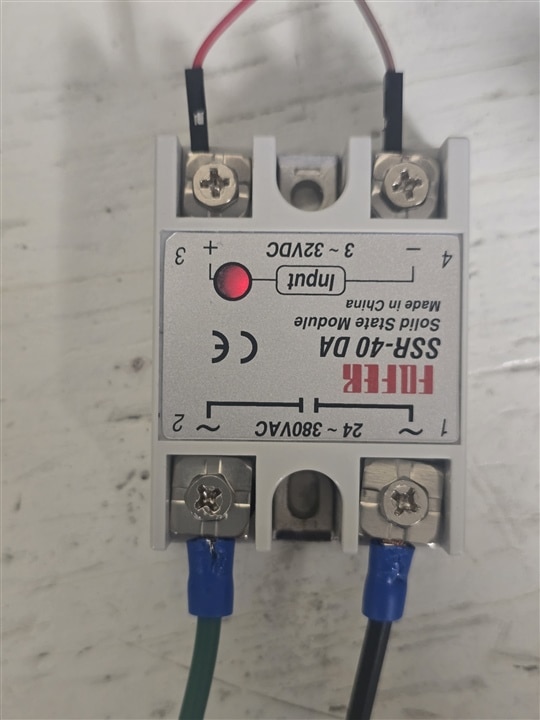
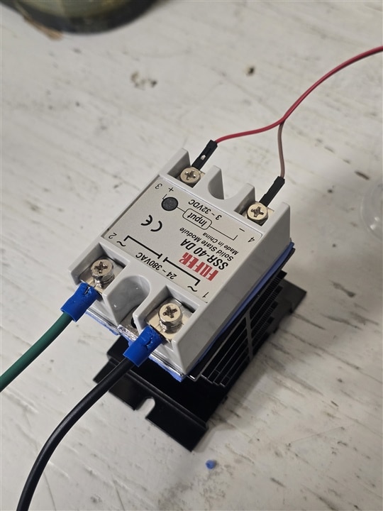
Figure 4. SSR test and heat sink assembly
#include <Arduino_RouterBridge.h>

void setup() {
    pinMode(D12, OUTPUT);
    // Start with the LED OFF (HIGH state of the PIN)
    digitalWrite(D12, HIGH);

    Bridge.begin();
    Bridge.provide("set_led_state", set_led_state);
}

void loop() {}

void set_led_state(bool state) {
    // LOW state means LED is ON
    digitalWrite(D12, state ? LOW : HIGH);
}
The future
Once the construction blocks are ready, it is time to implement the monitoring system and test the data sharing and control-aided cooling system. At this stage, it is possible to view the data on the UT325F thermometer and capture the data in the Arduino UNO Q for storage. The monitoring system must be implemented in order to view the data using the same web interface system. On the other hand, I had problems with serial port access in the Arduino App Lab, but there are other options such as Inter Process Communication (IPC) to create a data sharing service in the network.
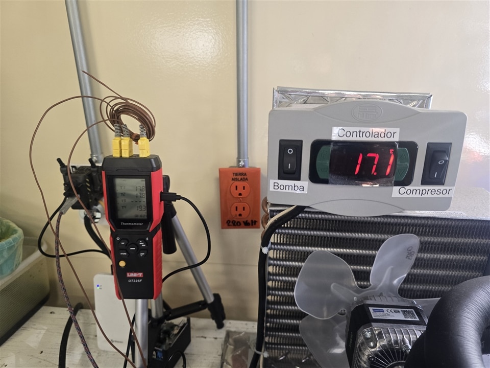
Figure 5. Isolated monitoring cooling system