


Hi. I welcome you to my third forum post as part of my participation in On The Line Design Challenge. In this post, I will show how to measure temperature and humidity using it with using just sensor, power supply, and two multimeters (one for temperature, second for humidity).
Current Outputs
The variant of sensor which we received as part of competition has current output. It works as current limiter. Sensor has no ground connection. It connects just to high voltage of power supply which need to be higher then 6V and maximum is listed as 30V. The sensor consume energy from this source and limit’s own power consumption based on measured properties. Output is in the range 4 – 20mA, so sensor always consume at least 4mA which it uses for its own operation. Remaining current is “wasted” for indicating measured value.
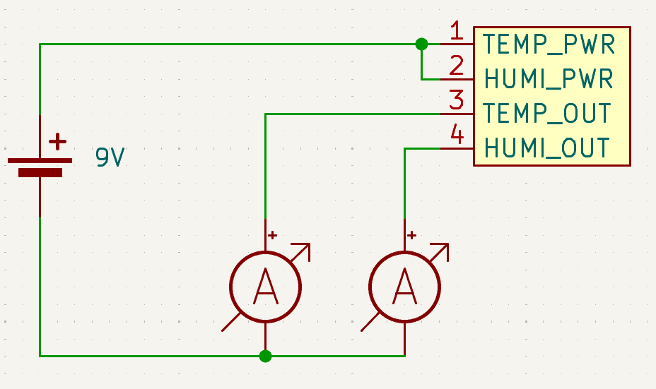
Let’s measure some currents which corresponds to humidity and temperature measured by the sensor. Schematics of connection is following. As I mentioned, power pins of sensor (1 and 2) goes to positive voltage of power supply, output of sensors (3 and 4) are connected via amperemeters to negative pin of power supply.
In reality when powered:

Converting Milliamperes to Temperature and Humidity
Formulas for converting measured current (mA) to real values are mentioned in printed manual which come with sensor:

I measured 7.77 mA on temperature output channel, and 13.020 mA on humidity channel. Let’s pass it to formulas:
°C = (7,77 – 4) * (100 / 16) = 23.5625 °C
%RH = (13,020 – 4) / 0,16 = 56.375 %