


With the software labs complete, it was time to move on to hardware. I think it was recommended that we start with software first, but I think hardware first (the path most P2P trainees chose) probably made more sense. In the software labs, we imported hardware definitions which were then used to create the board support package, etc. This becomes the platform for the software development side of MPSoC design. This hardware definition was created in Vivado.
The Vivado tool can be thought of as a starting point for Xilinx MPSoC design (SDSoC is another option, but we didn't end up using that in these labs). The programmable logic and hardware peripherals are all configured in Vivado before being exported as an HDF and imported into SDK.
Lab 1: Building a Basic MPSoC Design
The first thing to do when starting a new project is select the target part. Vivado even has the option to add known boards which are part of the MPSoC ecosystem. We selected the part on Ultra96-v2 which is the XCZU3EG-SBVA484-1-e.
Vivado allows the designer to create an overall hardware block diagram of the design from different components in the IP catalog. As will be seen later, we can even create our own custom packaged IP to add to this block diagram. The first item we added to the block diagram was the main component of the Ultra96-v2 board: the Zynq UltraScale+ MPSoC itself which we already selected the correct part number for.
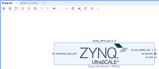 |
Once the MPSoC IP was added, we double-clicked to edit the configuration:
 |
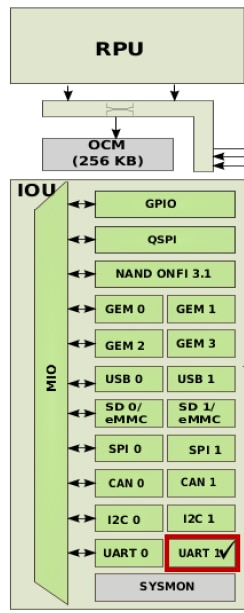
All the items in green are hardware peripherals of the MPSoC which can be customized in Vivado. Once a peripheral is enabled and customized, a check mark appears next to it on the MPSoC block design:
  |
Lab 2: PS Configuration Part 1 - HelloWorld
Continuing in lab 2, we began configuration of the I/O and peripherals. This lab covered configuring just the basics to get an application up and running.
There are two types of I/O, MIO and EMIO. EMIO is I/O which can map the processing system peripheral I/O to the programmable logic. The MIO are dedicated I/O for processor peripherals, especially high speed peripherals, which can't be routed via the EMIO.
We configured settings for the UART1 peripheral, MIO bank voltages, memory (DDR4), and clocks, before building the hardware platform for export to the SDK. We validated the design and then created a top-level wrapper for the design. This wrapper will later contain all the connections made in our hardware block design. A few PS-PL interface related options are enabled by default (clock, reset, AXI connection). We disabled these, as we were not ready to use the PL. The final step in Vivado was to generate the PL bitstream before exporting the HDF to SDK.
Once imported into SDK, we created and ran (using the existing BSP) a new "Hello World" application to test out the hardware configuration we created in Vivado.
Lab 3: PS Configuration Part 2 - MIO Peripherals
In this lab, we went through enabling all the peripherals available to the processing system and mapping applicable ones to MIO pins. This included GPIO, USB 0 & 1, SD 0 & 1, UART 0 & 1, SPI 0 and 1 (including additional chip selects; 2 for the mikroBUS and 1 for the on-board ADC), I2C 1, and DisplayPort peripherals. This is a very important step for getting all the peripherals on your board to work with the MPSoC+. We also enabled watchdog timers, timer/counters, and configured PS clocks.
Once again, we exported the hardware platform for import into SDK and tested Hello World and the memory tester application.
Lab 4: Using TCL in Vivado Embedded Designs
This lab went over using some of the various TCL functions available in Vivado for working on the hardware design. I have used TCL extensively when working with test benches for FPGA programmable logic designs. I have used it a few times for interaction with FPGA programming tools, but I haven't used it much for working with a hardware design project. Just about any GUI function in Vivado has an equivalent TCL function that can be used to accomplish the same task. Vivado has a TCL console built into the GUI where the commands can be run, or a script can be written to execute various TCL commands automatically. A script could be written, for example, to instantiate various IP blocks and connect them all together, rather than having to manually add IP blocks and connect their ports by hand The lab went through the exercise of exporting the hardware block design TCL script from Vivado. This script makes it easy for a colleague to replicate the design on their end, rather than having to re-draw everything from scratch.. It is always helpful to see TCL be integrated into vendor tools with custom commands. It is well worth the time to learn some TCL if you haven't used it before.