


In this series, we are provided an Ultra96 board and a series of training modules focused around three areas - Hardware (the FPGA side), Software (the microprocessor side), and Petalinux (the OS side).
In this blog post, I'll outline the Software lessons 6 through 12. There was a lot covered, so I'll be brief.
Lab 06 - First Stage Bootloader
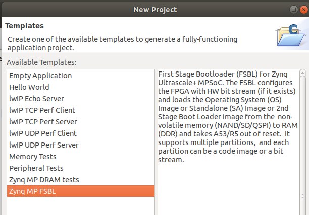
In this lab, we create the First Stage Bootloader (FSBL). This is needed as a first step to running our application as stand-alone on the Ultra96 as stand-alone, instead of launching over JTAG. We learned a lot about the boot sequence inside of the MPSoC, which suppots many nice features such as secure booting, and booting from a selection of devices such as JTAG, QSPI, NAND, SD, and eMMC.
For the lab, all we really had to do was create a new 'project template' and choose First Stage Bootloader from within SDK. Then SDK takes care of the rest for us and builds it.
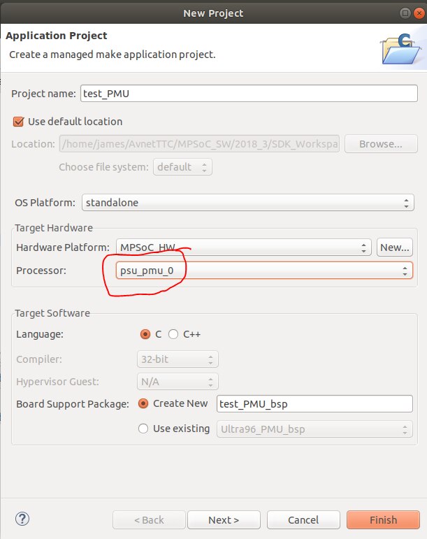
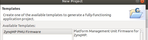
We also had to create a PMU file - Platform Management Unit - to run after the FSBL and before our application. This was done in a similar manner as above where we add a new 'application project' and change the processor dropdown to "psu_pmu_0".
From the lab, we learn what the PMU is responsible for:
The PMU performs the following set of tasks.
• Initialization of the system prior to boot.
• Power management.
• Software test library execution (optional).
• System error handling.
Lab 07 - SD Card boot up
In this lab, we take the FSBL and PMU along with our bitstream and our application and create a .bin file. This gets loaded on the SD Card, and we are finally able to put that in the Ultra96, power it up, and it will start on its own and run the program. This means that it can now run 'untethered' from the computer. The .bin file is the boot image. We tell the Ultra96 to boot from SD via the DIP switch on the board and it finds the .bin file and executes it.
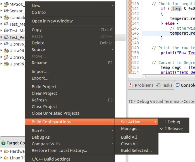
We also change the build version from "debug" to "release". This does cause an issue with one of the interrupt tests as myself and others noticed. Charles Mao outlined in this blog post, there is an issue with how the test was coded, and how the SDK interprets the debug levels differently from Debug to Release.
The Ultra96 has an integrated cooling fan, and it is software controlled. This means that it can sometimes turn off, and that definitely happens during this test. The sad thing is that the coding issue causes the application to hang, and fan has turned off. The result is that the board heats up considerably while I am troubleshooting.
Temperature Alarm(0) HIGH Threshold is 52.700 Centigrade.
Temperature Alarm(0) LOW Threshold is 42.698 Centigrade.
VCCINT Alarm(1) HIGH Threshold is 0.637 Volts.
VCCINT Alarm(1) LOW Threshold is 1.037 Volts.
VCCAUX Alarm(3) HIGH Threshold is 1.597 Volts.
VCCAUX Alarm(3) LOW Threshold is 1.997 Volts.
Alarm 0 - Temperature alarm has occured
The Current Temperature is 63.075 Centigrade.
The Maximum Temperature is 63.658 Centigrade.
The Minimum Temperature is 62.516 Centigrade.
But other than that, this lab went well.
Lab 08 - Importing and exporting
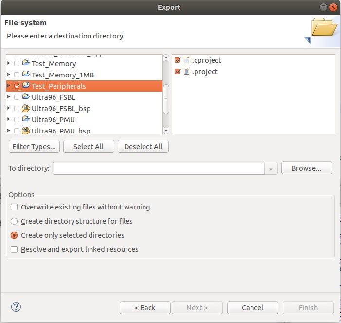
In this lab, we discuss how to import and export hardware and settings. Most is done via File-->Export and File --> Import.
We learn that we can't simply copy and paste the directories because things won't build properly.
We are able to export our system debugger settings, breakpoints, and software repositories including drivers and libraries and custom BSPs.
Lab 09 - Interrupts and Exceptions
Here we learn about how interrupts are handled on the MPSoC. There are hardware (physical) interrupts and software interrupts, commonly called exceptions.
When an interrupt happens, there is a specific sequence of events which must happen to cleanly handle the interrupt.
Here is a rough outline:
- Finish execution of current process
- Store processor status into memory
- Disable interrupts (so we don't get additional interrupts during the handling of the first one)
- (I wish I could disable the interruptions to my interruptions at work...)
- Switch over to the ISR (interrupt Service Routine) and handle the interrupt
- Re-enable interrupts
- Re-load program variables from step 2
- Pick up regular program execution from where we left off in step 1.
For lots of reasons, ISRs should be kept short and sweet. If we want to print something out to a serial port when an interrupt happens, it would be best to just set a flag in the ISR, then let the regular program write it out in its own time.
In the lab, we use the LCD Dimmer application that we started with in the Software labs. We actually create it from scratch in this lab, but the program ends up being the same. We start with a program that doesn't have the interrupt, then we manually add it to the code.
I noticed that there was an incorrect screenshot in this lesson, which I think was a hold-over from the MiniZed training course that this training seems based on.
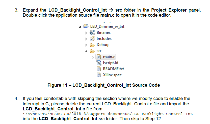
The screenshot shows the "LED Dimmer" application instead of "LCD Dimmer". That was definitely the app we created for the MiniZed since we didn't have any expansion cards for it.
Lab 10 - File System
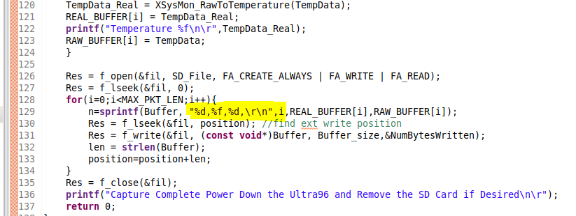
In this lab, we learn about the Xilinx included libraries; and specifically about the xilffs - Xilinx FAT file system library. We read in temeprature values and write them out to a CSV file on the SD Card.
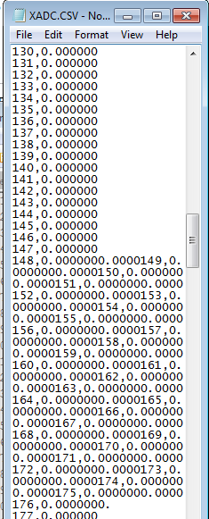
The CSV file ended up very messy. It looks like the \r\n (carriage return / new line) don't work properly in the code, and somehow I got a lot of zeros instead of actual readings.
Lab 11 - Click Mezzanine board
We create a simple application using the LSM6DSL Click Board. The lab has us set up a SPI slave device (the Click Board) and we read in the temperature values and print them on the serial console.
There is a pretty good introduction to the MikroBUS architecture and the availability of boards. It certainly looks like they have their own ecosystem of expansion boards; although there would need to be a good use case for something like an accelerometer or LCD click board on a $250 MPSoC / FPGA development board when a $35 Arduino interface with these sensors just as easily. Now obviously the Atmel 328 is nothing compared to the Xilinx ZU3EG... I suppose that for someone getting into electronics could start with an Arduino, and later on step up into the big leagues with an FPGA trainer board and this simplifies a lot of the work of physically interfacing. And also, the click boards certainly aren't exclusive to the Ultra96 - they have mezzanines for things like the Beagle Bone, RaspberyPi, and the humble Arduino.
Video walkthrough
See the video below for a walkthrough of these lessons.
"I can haz clickboard" or "don't tell me about your watchdog timer"
And with that, I'm on to the Petalinux lessons. Hopefully I can get them done quickly before the end!