


Introduction
This is the final project blog for Path to Programmable III using the MiniZed Xilinx ZYNQ FPGA board. In this project blog, I will show how I made an internal car safety device using some Grove sensors and the MiniZed FPGA board.
From a global viewpoint, a lot of time is spent within the indoor air compartment of vehicles. A German study on mobility has revealed that, on average, people spend 45 minutes daily inside vehicles. I believe in my country Bangladesh the time is even more. In recent years the number of cars has increased to around 43 million vehicles in private households. This means that more than one car can be used in every household. The ratio has been growing. “Overall and especially outside the cities, the car remains by far the number one mode of transport, especially in terms of mileage”. Therefore, numerous international studies have addressed different aspects of indoor air hygiene, in the past years. The car indoor air pollution, related to VOCs, COx, PMs, microbials, BFRs, OPFRs, cigarettes, electronic smoking devices, high molecular weight plasticizers, and NOx are summarized in the form of a review.
Toxic air pollutants like carbon dioxide and nitrogen oxide don’t just float around in the outside air: the insides of our cars can also be full of unhealthy air, which can gravely affect our health. Indoor “bad air” is often a cause of discomfort, but beyond this, it can also lead to serious illnesses.
A recently published report of Bakhtiari et al. focused on measurements of benzene, toluene, ethylbenzene, xylene (BTEX), acetaldehyde, and formaldehyde concentrations in indoor car compartments of different models and ages, before and after the refueling process, with different fuel types (compressed natural gas (CNG), gas, and liquefied petroleum gas (LPG)). The average levels of formaldehyde ranged between 806 (+/-323) and 1,144 (+/-240) ppb, respectively. In 2016, the Committee for Indoor Objectives (AIR) derived a benchmark I (precautionary value) of 0.1 mg per cubic meter of indoor air. This corresponds to 100 micrograms/ m3. This value should not be exceeded even for a short term. The World Health Organization (WHO) recommends a guideline of 0.08 ppm (0.1 mg/m3). Acetaldehyde average concentrations showed results between 410 (+/-223) and 482 (+/-91) ppb, respectively. The BTEX reached values below the guideline amount for all used car models. Interestingly, refueling increased the in-cabin levels of pollutants primarily the CNG and LPG fuels—the concentrations of the above-mentioned BTEX were found to be significantly higher for gasoline, during each observation.
There are some preexisting ways to filter your car’s cabin air clean, particularly with the settings on your car’s dashboard. Fan speed, ventilation mode, and cabin air recirculation options can protect your respiratory health, but these do not filter many of the smaller and hazardous particles in the air.
In this project, I used the Grove Multichannel Gas Sensor & Grove BME280 temperature and pressure sensor for measuring some very important air quality parameters inside the car like CO, NO2, NH3, CH4, C3H8, C4H10, H2, C2H5OH, temperature, and air pressure. If any parameters go beyond the normal range it alerts the users/driver inside the car by ringing sound. It also helps to detect any fuel leakage like CNG or LPG which may lead to severe accidents. Getting the audio alert the users/driver may take necessary action to save themselves from hazardous gas as well as any future threat of fuel leakage.
Components Used In The Project
The main brain of the project is a Xilinx ZYNQ FPGA-based MiniZed Board. You can learn more about this board from my previous blogs. Without this board, the following components were used in my project. All the components are from SeeedStudio.
| {tabbedtable}Components | Details |
|---|---|
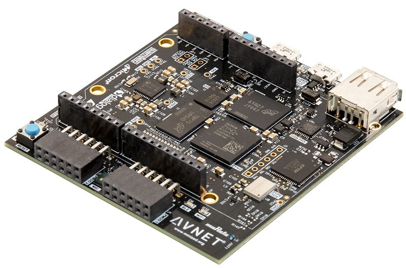
| MiniZed Board |
MiniZed is the perfect launching pad for your next Zynq-7000 SoC project. Featuring a Zynq Z7007S, which integrates an Arm Cortex-A9 processor with Xilinx Artix-7 programmable logic, the MiniZed is a low-cost yet versatile development board targeted for entry-level Zynq designs. This compact single board computer features on-board connectivity through USB, Wi-Fi, and Bluetooth. Peripherals can be plugged into dual Pmod-compatible connectors, the Arduino-compatible shield interface or the USB 2.0 host interface. JTAG circuitry is incorporated onto the MiniZed base board, so with a single microUSB cable to your laptop you are already up and running. User LED’s, a button and a switch allow for a physical board interface. |
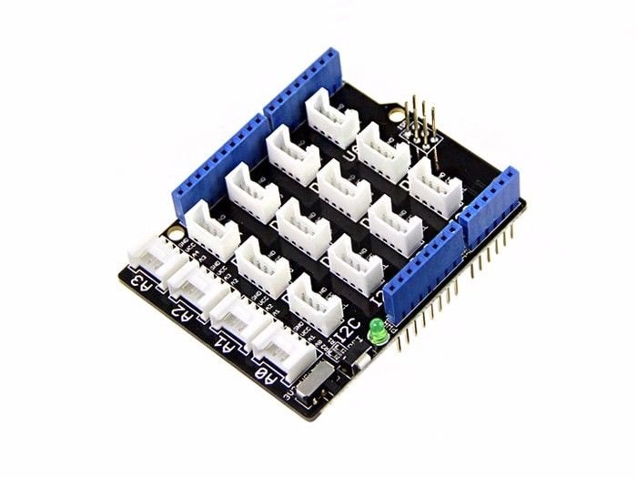
| Grove Base Shield V2.0 |
Base Shield provides a simple way to connect with Arduino or any Arduino-compatible boards and helps you get rid of breadboard and jumper wires. There are 16 onboard Grove connectors including 4 x Analog, 7 x Digital, 1 x UART, and 4 x I2C. Apart from the rich Grove connectors, on the board you can also see an RST button, a green LED to indicate power status, ICSP pin, a toggle switch and four row of Arduino pinouts. |
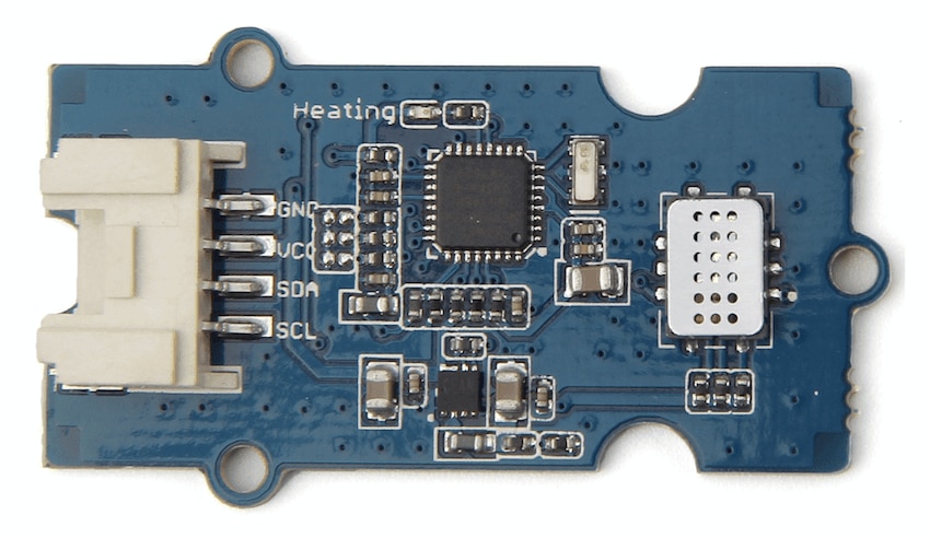
| Grove – Multichannel Gas sensor |
Grove – Multichannel Gas sensor is an environment-detecting sensor with a built-in MiCS-6814 which can detect many unhealthful gases, and three gases can be measured simultaneously due to its multi channels, so it can help you to monitor the concentration which more than one gas. This sensor belongs to Grove system, and you can plug it onto the Base shield and work with Arduino directly without any jumper wires. The interface of it is I2C, so plug it onto the I2C port of Base shield, and then you can start to work it. Detectable gases by the sensor:
|
| Grove BMP280 Sensor |
Grove - Barometer Sensor (BMP280) is a breakout board for Bosch BMP280 high-precision and low-power digital barometer. This module can be used to measure temperature and atmospheric pressure accurately. As the atmospheric pressure changes with altitude, it can also measure the approximate altitude of a place. It can be connected to a microcontroller with I2C (integrated with Grove socket) or through SPI bus. |
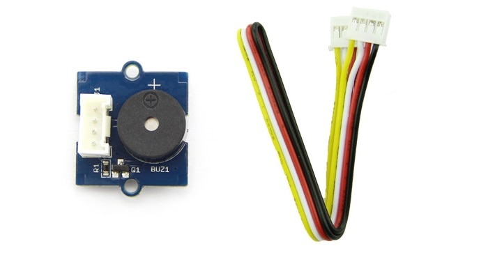
| Grove Buzzer |
The Grove - Buzzer module has a piezo buzzer as the main component. The piezo can be connected to digital outputs, and will emit a tone when the output is HIGH. Alternatively, it can be connected to an analog pulse-width modulation output to generate various tones and effects. I used this here to generate an alert signal for any abnormal sensor reading. |

Hardware Connections
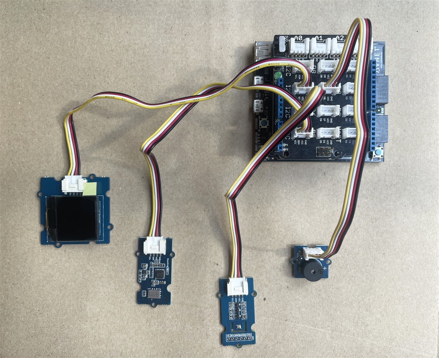
I used two I2C Grove sensors for measuring important air quality parameters inside the car, one Grove I2C OLED display for displaying the measured parameters, and one Grove buzzer for alerting the driver and passengers of any abnormal concentration of any gases. For connecting the sensors and the buzzer with the MiniZed board I used a Grove Base Shield for Arduino. As the MninZed board has Arduino compatible header, we can easily plug a base shield with the MiniZed board. I placed the Grove base shield on top of the MiniZed board as shown in the image below.

After adding the Base shield connecting the sensor with the shield is very easy. All Grove sensors and actuators support plug-and-play connection with the Grove connector through Grove 4 wires cable. I connected the Grove OLED display, Grove Multichannel Gas sensor, and Grove MBE280 sensor with three I2C ports of the base shield. You can choose any I2C port for any one of them. I connected Grove buzzer to the D7 of the base shield. Any other port can be used with necessary changes to the hardware design. The details of the hardware design is provided in the next section.

Hardware Design with Vivado
After connecting the display, sensor, and buzzer with the MiniZed board we need to perform hardware design for the FPGA using the Vivado design tool. I am using Vivado on my Ubuntu 20.2 host machine. For running Vivado I used the following command from the Ubuntu terminal.
source /tools/Xilinx/Vivado/2023.1/settings64.sh
vivado
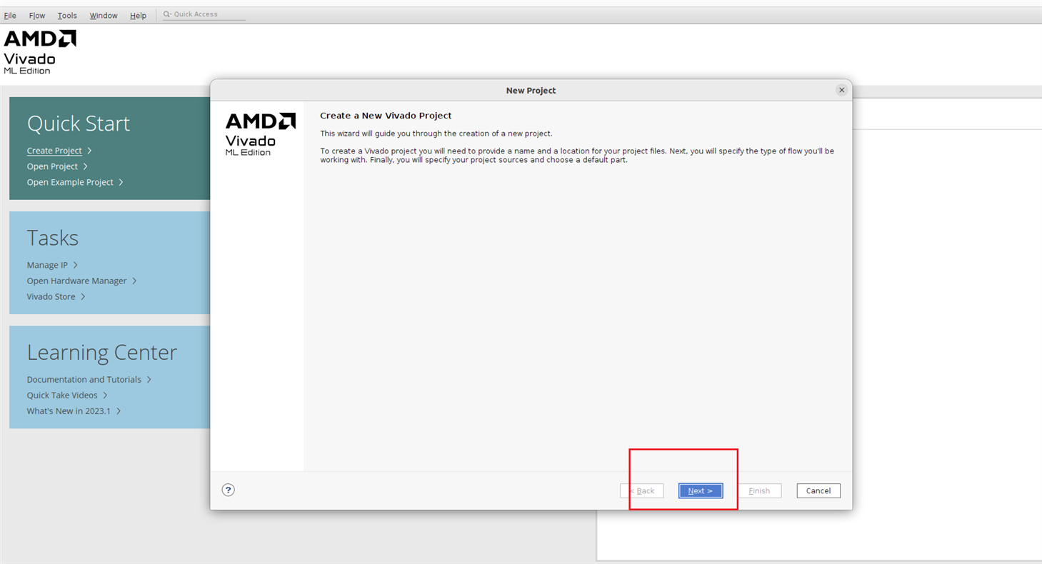
After running the Vivado first you need to create a project. Click on the Create Project option shown in the image below.

A new project window will open. Click on Next.
Give a name for your project and click on Next.

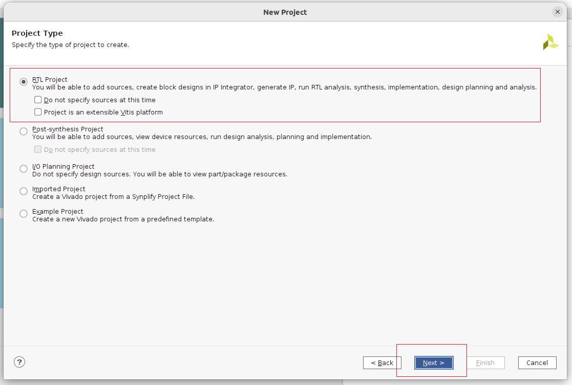
Choose RTL Project and click on Next.
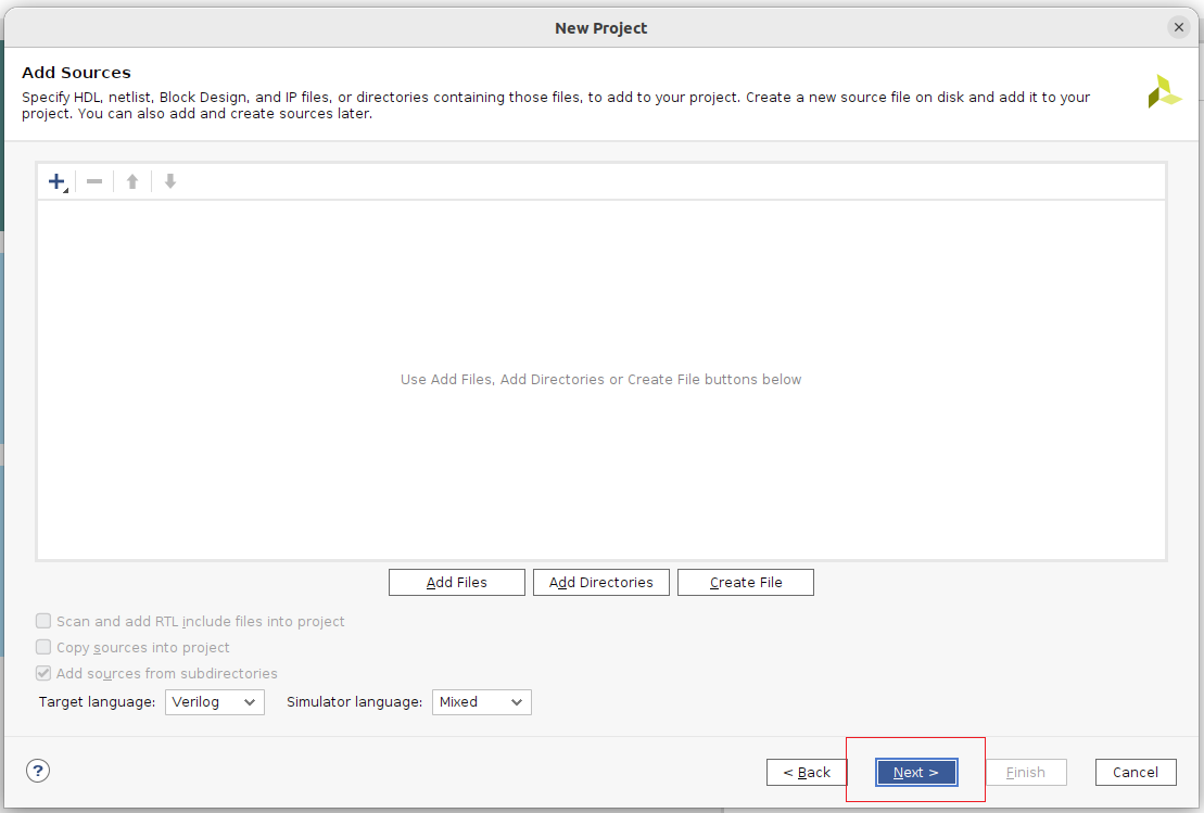
We are not going to add any sources at this time. So, just click on Next.
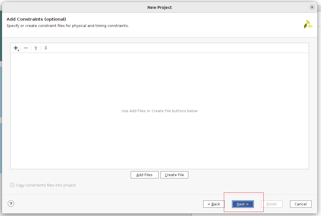
Do the same for the Constraints. We will add a constraint later. Click Next to go to the next step without adding or creating any constraints at this time.
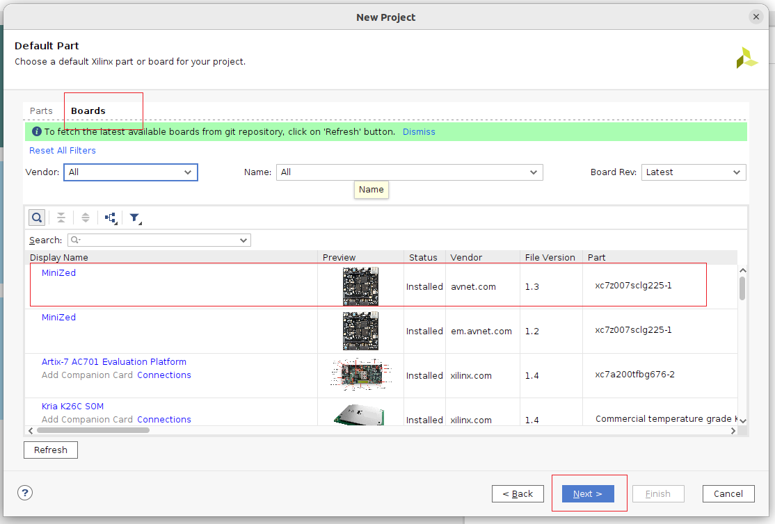
Now you need to add proper hardware parts for your project. I am going to use MiniZed board for my project. To add the board click on the Board tab and choose your preferred board (MiniZed in my case).
You will get a Project Summary as shown in the image below. Click on Finish to complete the project creation.

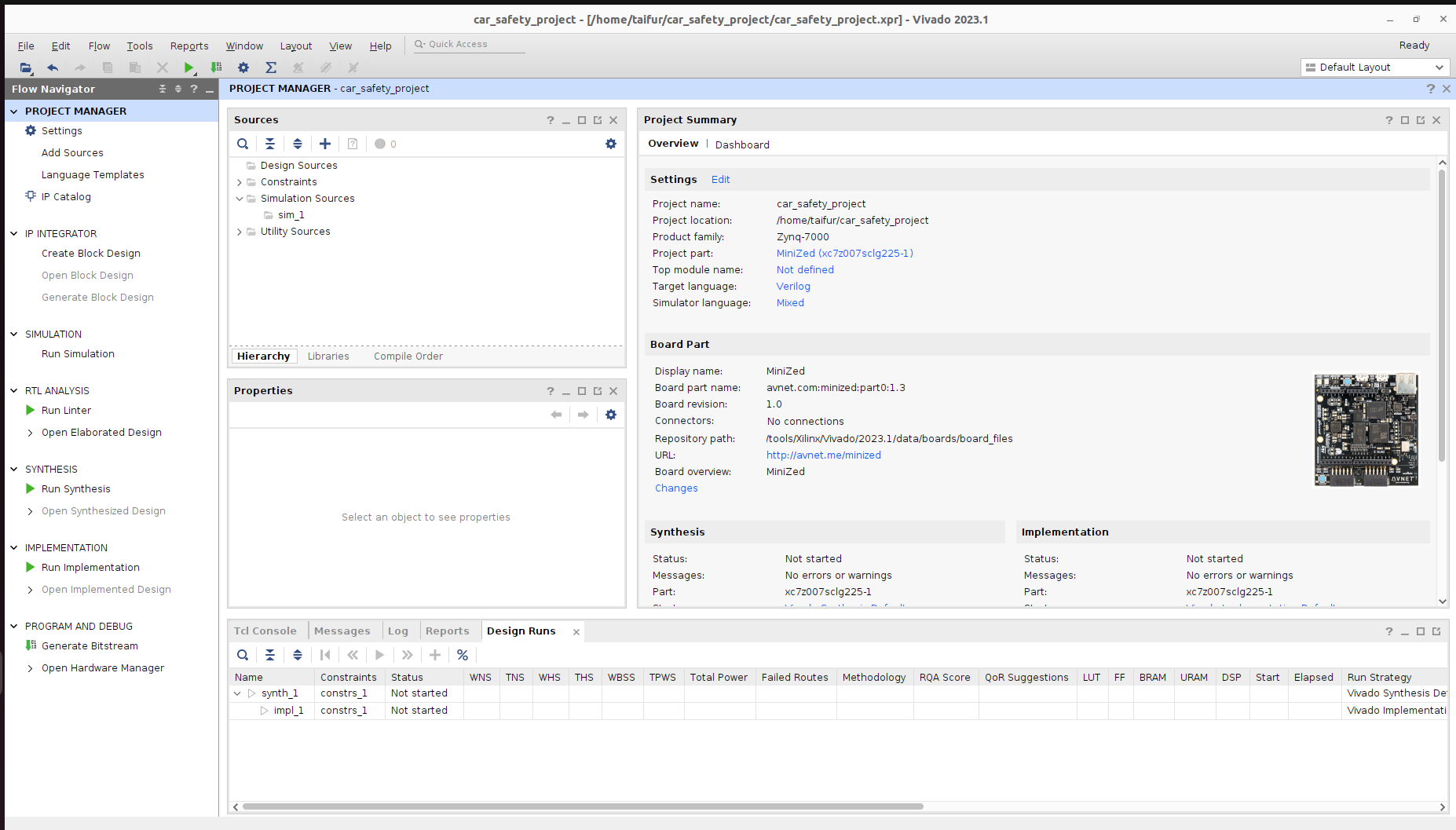
You see a project is successfully created. A more details project summary is visible here.
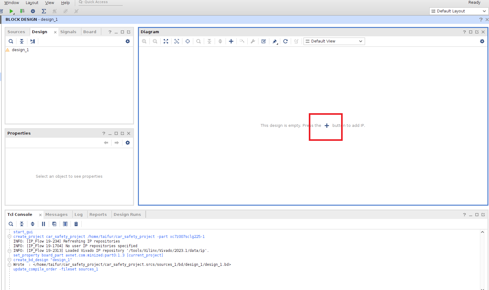
Now, we are going to start our design. From the Flow Navigator click on Create Block Design. Give the name of the block and click on OK. You may also keep the default name.

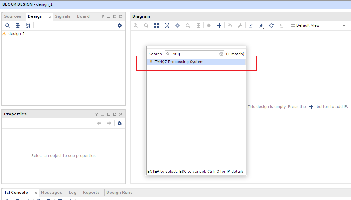
From the middle of the Diagram workspace click on the + sign.
Type zynq on the search bar and select ZYNQ Processing System from the suggestion.
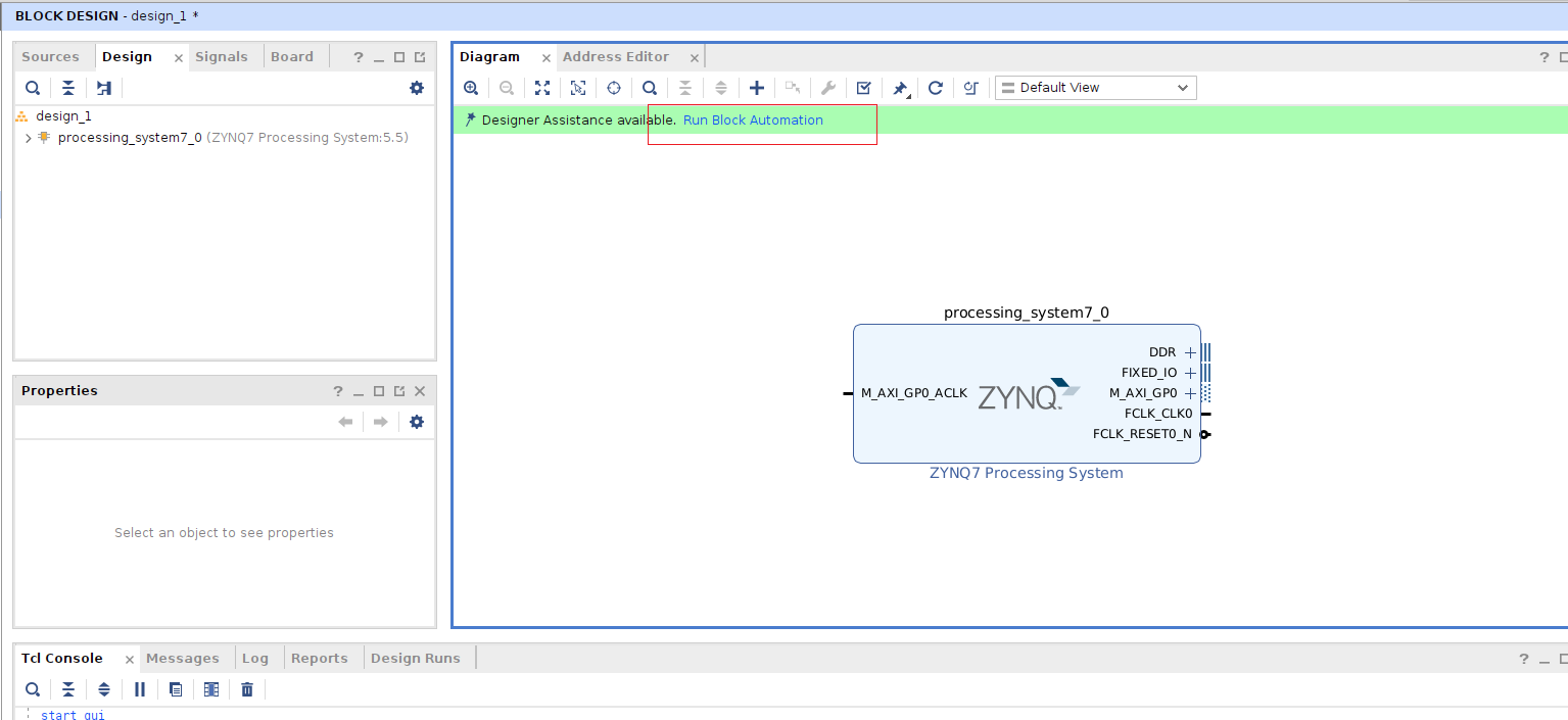
Click on Run Block Automation. It will automatically create the necessary connection for you.
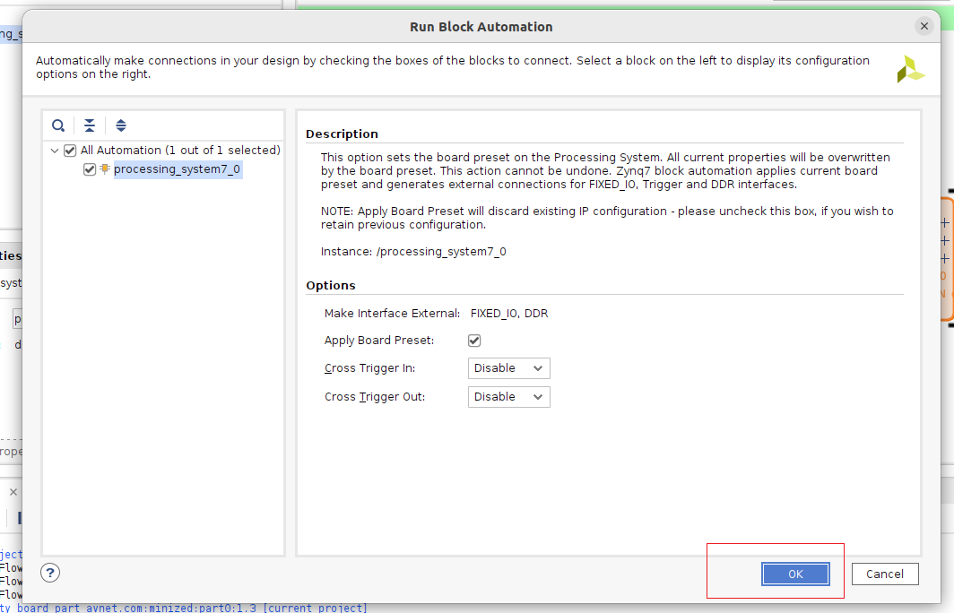
A new dialog box will be opened after running the block automation. Be sure that all checkboxes are checked and click on OK.
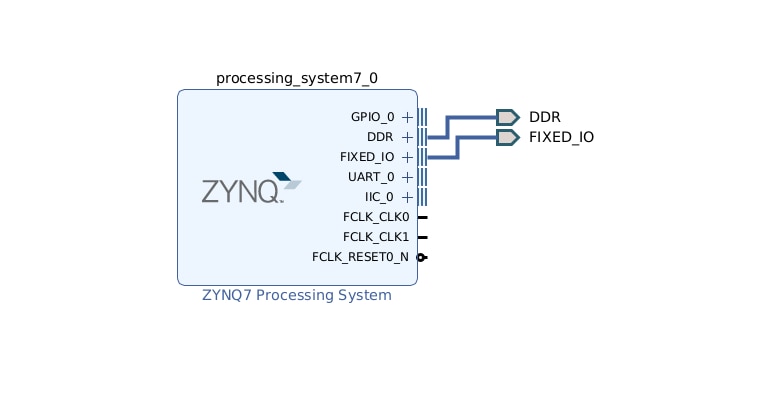
You will see what the block will look like in the image below. Now, we need to add some extra peripherals to the processing system for interfacing with external sensors and displays. To do so double-click on the ZYNQ processing block.

After double-clicking on the block a new customize window will be appared.
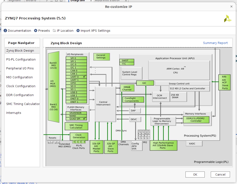
From the Page Navigator palate click on Peripheral I/O Pins and choose UART1, I2C0, and GPIO MIO and GPIO EMIO by marking the corresponding check boxes.
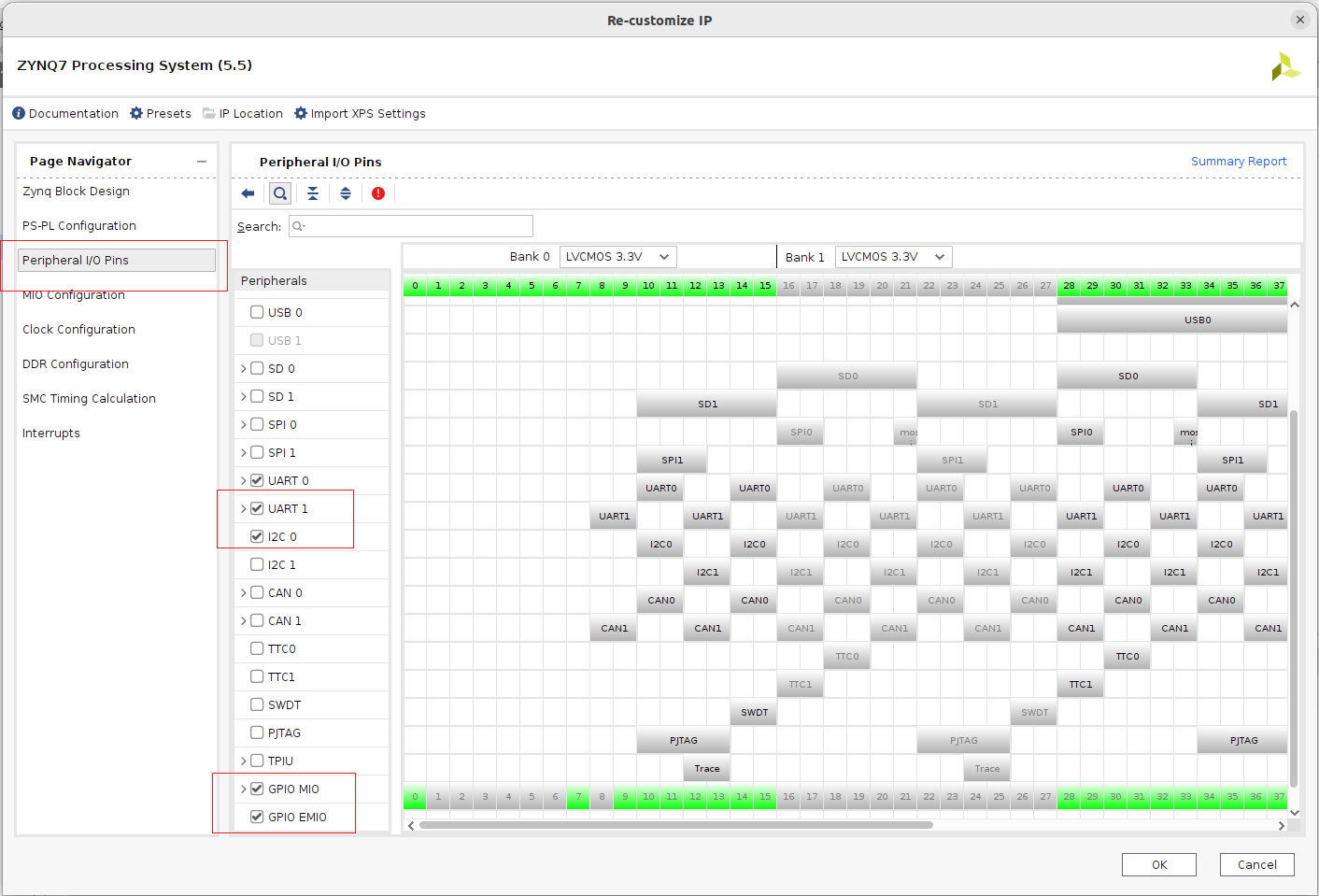
Set EMIO GPIO width as 1 as we will add only one buzzer with the GPIO.

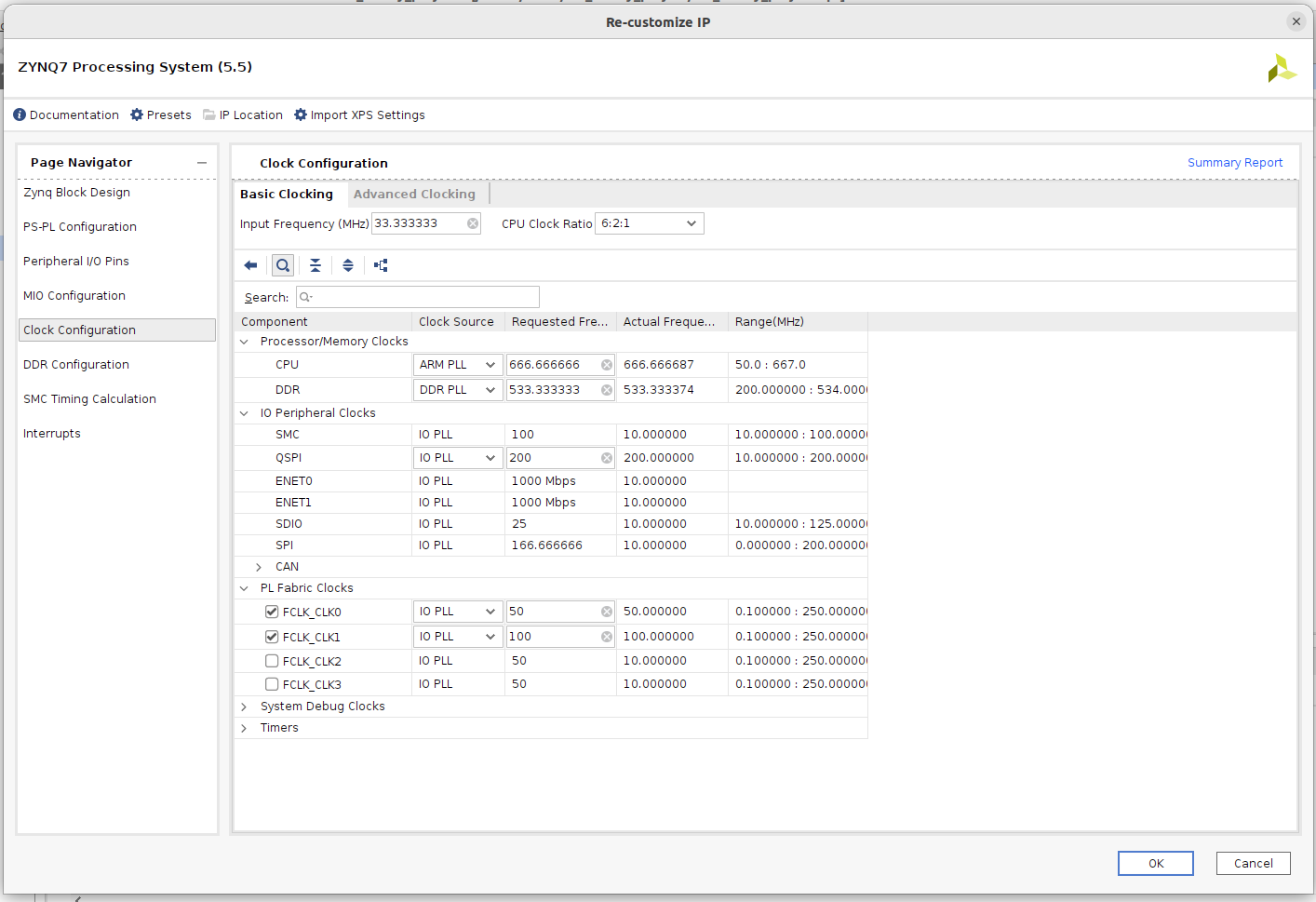
Check all the clock frequencies are as follows.
After confirming click on OK and will see the selected peripheral is marked now. Again click on OK to return to the block.

You will see the block design is updated as follows.
Right-click on IIC_0 and select Make External.

You we see the block is updated as follows.

Do the same for GPIO_O.

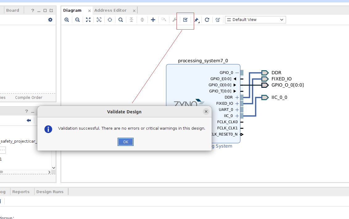
We completed the necessary modification on the processing block. Now, validate the design by clicking the validating icon. If validation is successful select OK.
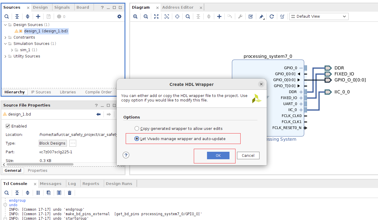
Now you need to create an HDL Wrapper for the design. Right-click on the design_1 from the Sources tab and click on Create HDL Wrapper.

Choose the Vivado manage wrapper option and click on OK.
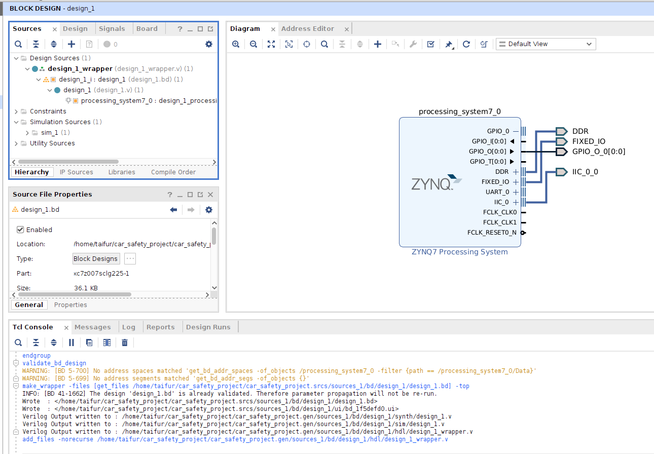
HDL Wrapper will be created and you will get the following output as shown in the image below.
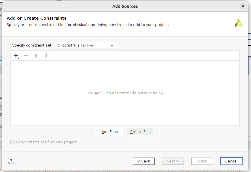
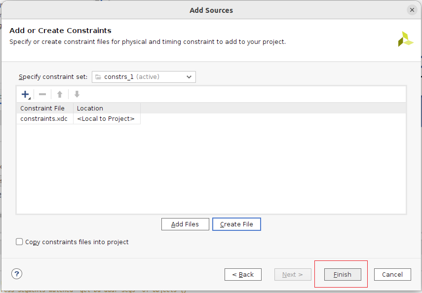
Now we will add constraints to our design. Click on Add Sources....

Choose to Add or create constraints and click next to continue.

Click on the Create File option.
Give a name for the constraint file and click OK.
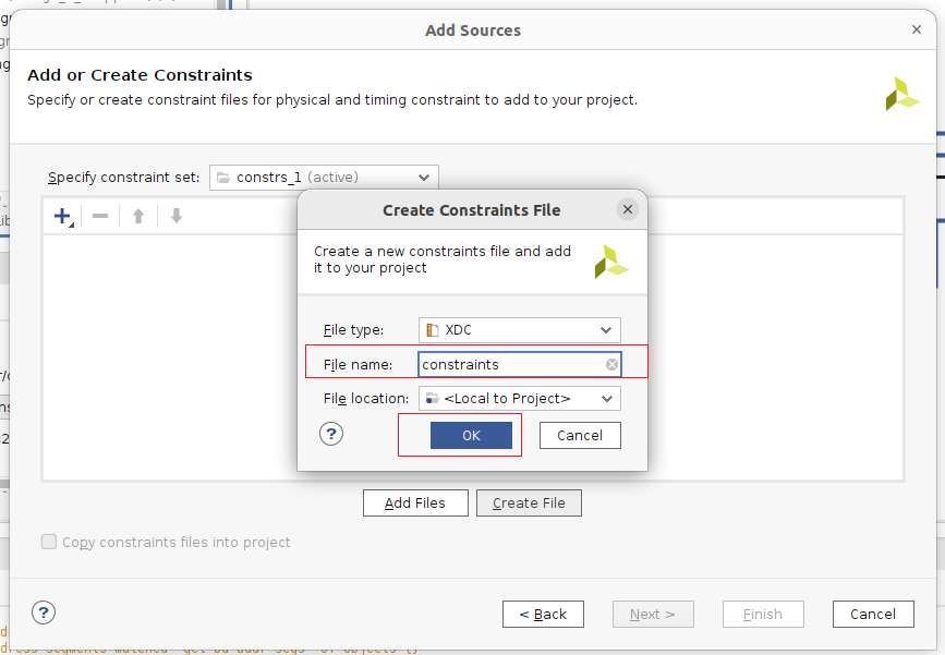
Finally, click on Finish.
Double-click on the newly created constraint file with the .xdc extension to open it and paste the following code on the editor and save it.
set_property PACKAGE_PIN N8 [get_ports {GPIO_O_0 }]; #Arduino D7 pin
set_property IOSTANDARD LVCMOS33 [get_ports GPIO_O_0]

# ----------------------------------------------------------------------------
# I2C bus
# ----------------------------------------------------------------------------
# Bank 35
set_property PACKAGE_PIN G15 [get_ports {IIC_0_0_scl_io        }];  # "G15.I2C_SCL"
set_property PACKAGE_PIN F15 [get_ports {IIC_0_0_sda_io         }];  # "F15.I2C_SDA"
# Set the bank voltage for IO Bank 35 to 3.3V
set_property IOSTANDARD LVCMOS33 [get_ports -of_objects [get_iobanks 35]];

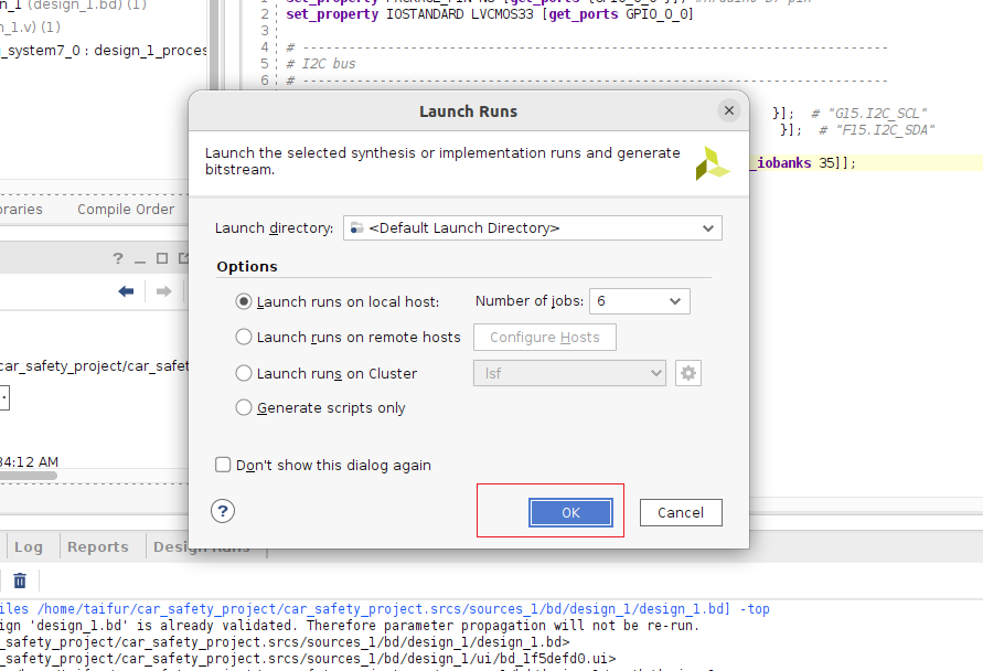
Now, from the Flow Navigator click on Generate Bitstream and click on Yes for the information window.

Click OK to launch the run with the default configuration.
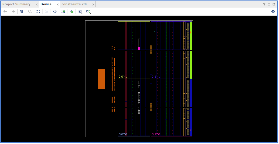
After the generation of the Bitstream, open it by clicking OK.

You will see the following image.
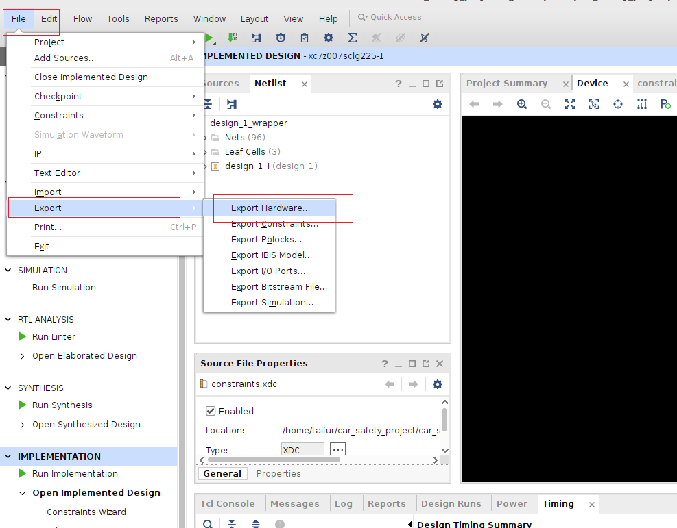
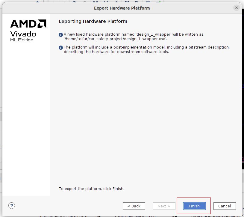
Well done. We have completed our hardware design successfully. Now we will export the hardware. From the File->Export choose Export Hardware.
Click on Next.

Choose the Include bitstream option and click on Next.

Change the name if you like or just click on Next with the default name.

Finally, click on Finish.
The hardware design is created and exported for the next step. Now we are ready to write code for the ZYNQ processing system for interfacing with external sensors and hardware. Follow the next step for developing software.
Developing Software with Vitis
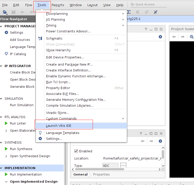
After completing the hardware design the next step is to develop the firmware for the hardware. Software for Xilinx devices is designed using Vitis. You can run Vitis separately or from the Vivado. To run vitis from the Vivado go to the Tools menu. Then choose Launch Vitis IDE.
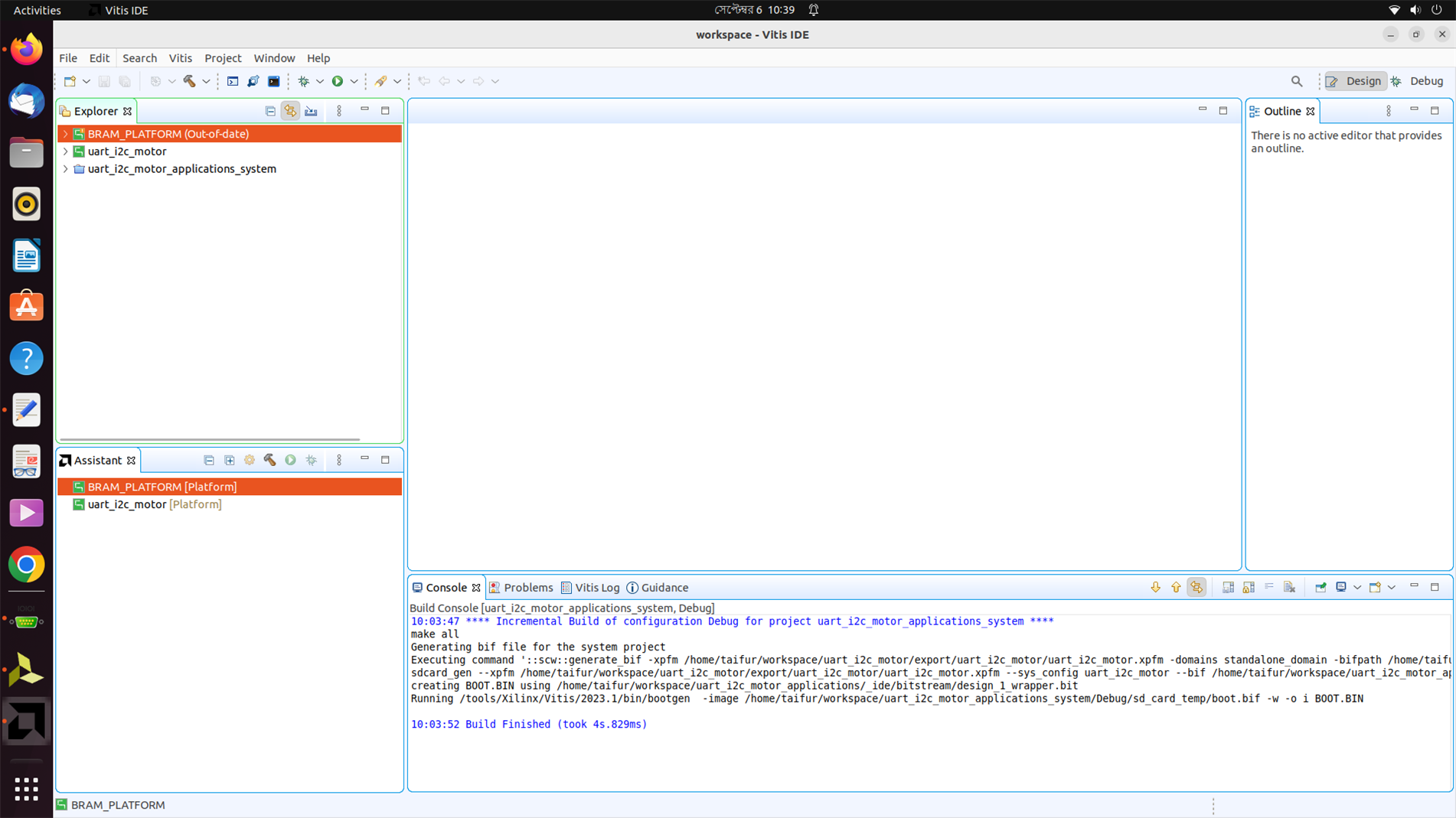
The Vitis IDE will be opened. It will show if any projects were created earlier using Vitis.
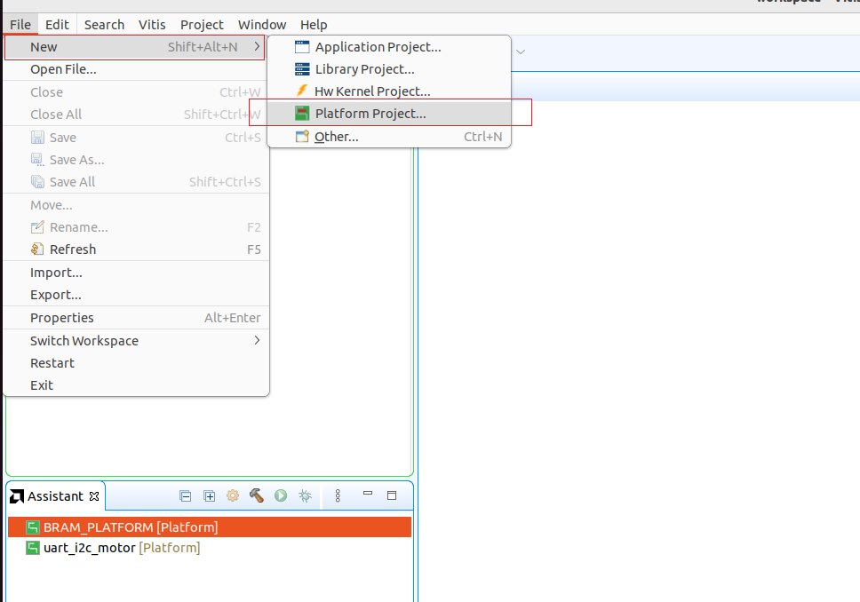
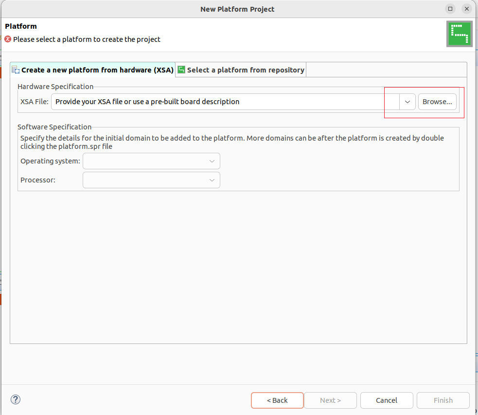
First, we need to create a platform project for the hardware we just created and exported from the Vivado and then we will create an application project. For creating a platform project go to the File menu and from the New choose Platform Project.
Give a name for the project and click Next.

You need to choose the hardware XSA file for any platform project. Click on Browse... to choose the XSA file.
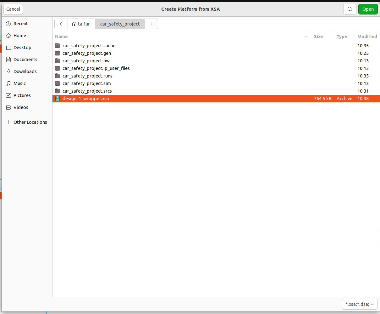
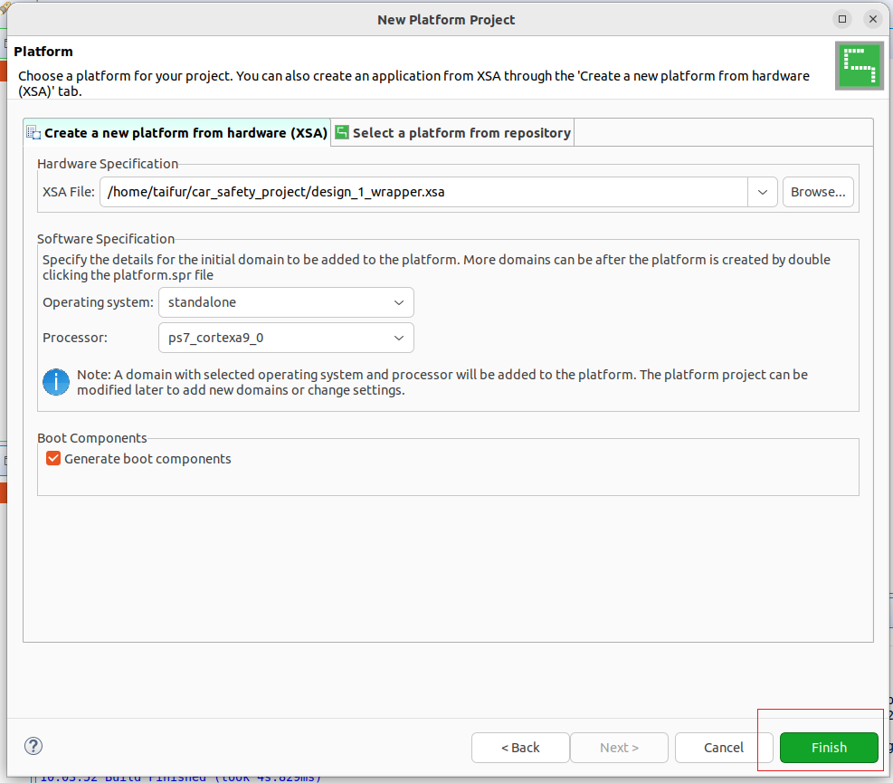
Choose the hardware XSA file you just exported from the Vivado and click Open.
Now, click on Finish.
The platform project is successfully created from the XSA file we selected and is opened now.
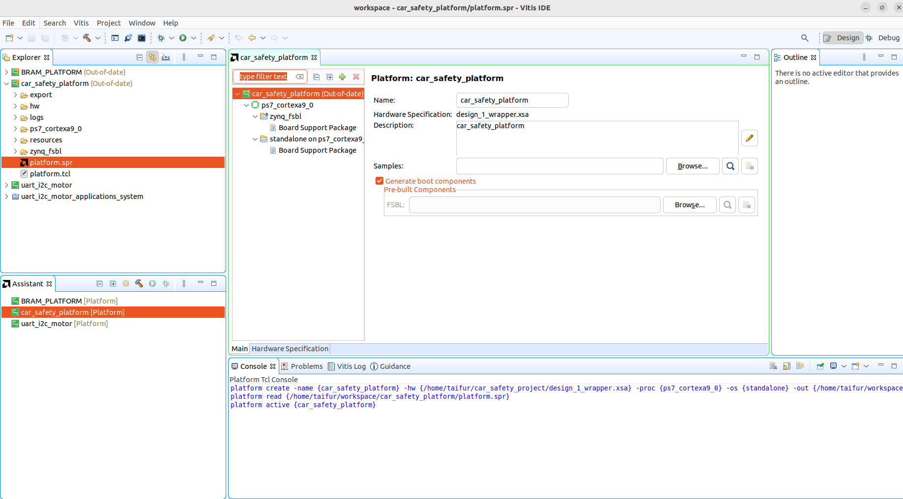
Build the platform project by right-clicking on the platform project you just created.
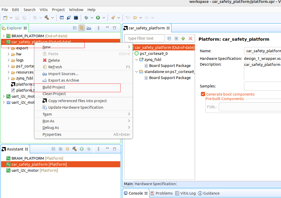
If everything goes well the project will be successfully built and you will get the confirmation from the Console.

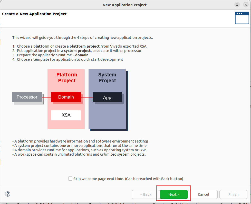
Now we are ready to create an application project on top of this platform project. To do that click on Application Project from the File menu.
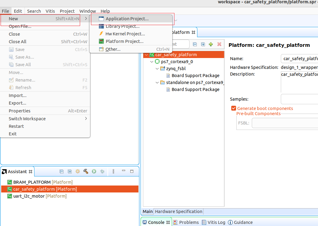
A new window will open. Click on Next.
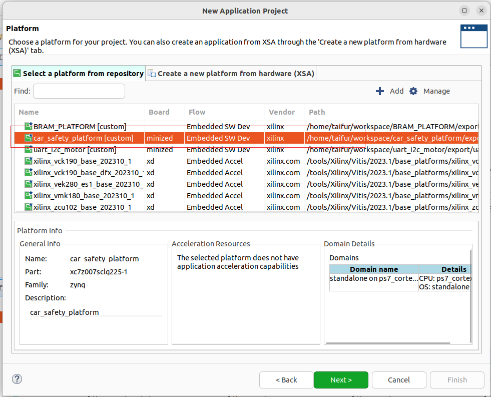
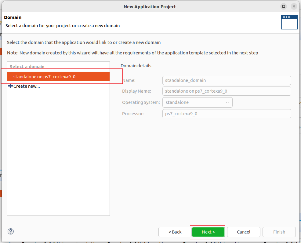
Choose the platform project you just created and click on Next.
Give a name for the application and click on Next.

Again click on Next.
Choose the Hello World template application and click on Finish.

The project will be created and opened automatically.

Expand the src directory to find all the source files in the project.
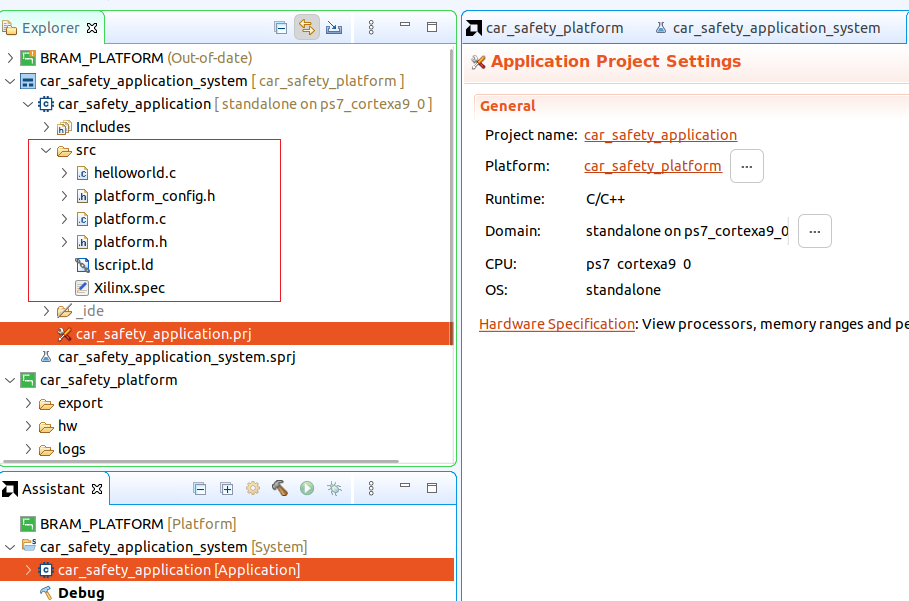
The helloworld.c is the main source file. Double-click on it to open the file in the editor.
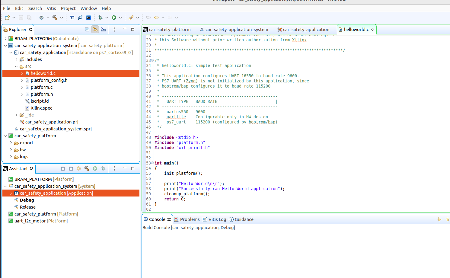
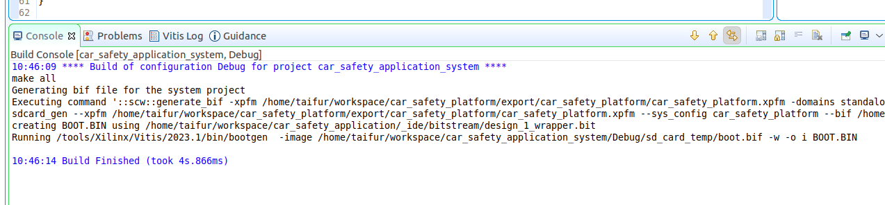
Now, let's build the project by right-clicking on it to check everything is working so far.
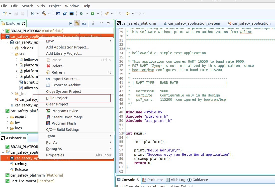
The project was built successfully as shown in the Console. Let's run the application on our target hardware.
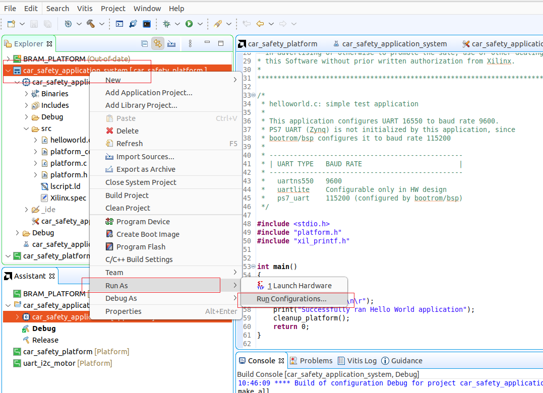
Attach the MiniZed board using a USB cable to your PC. Right-click on the application project and select Run As -> Run Configurations...
Click on System Project Debug and then click on the + icon as shown in the image below.
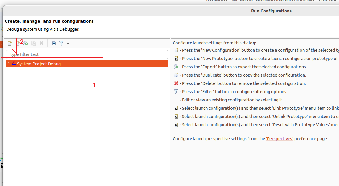
Your project will be added to the Project Debug option.
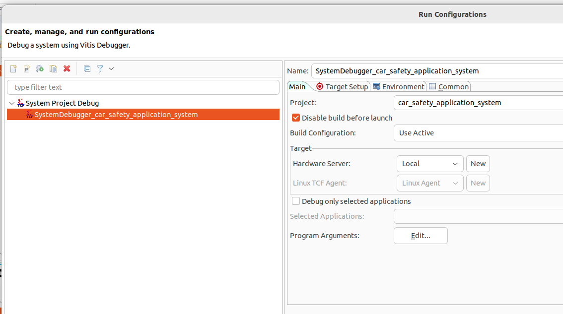
Click on your application and from the Target Setup tab make sure all options are selected.
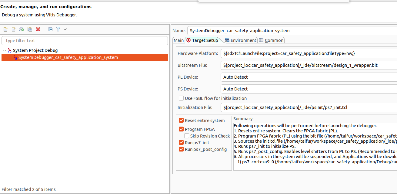
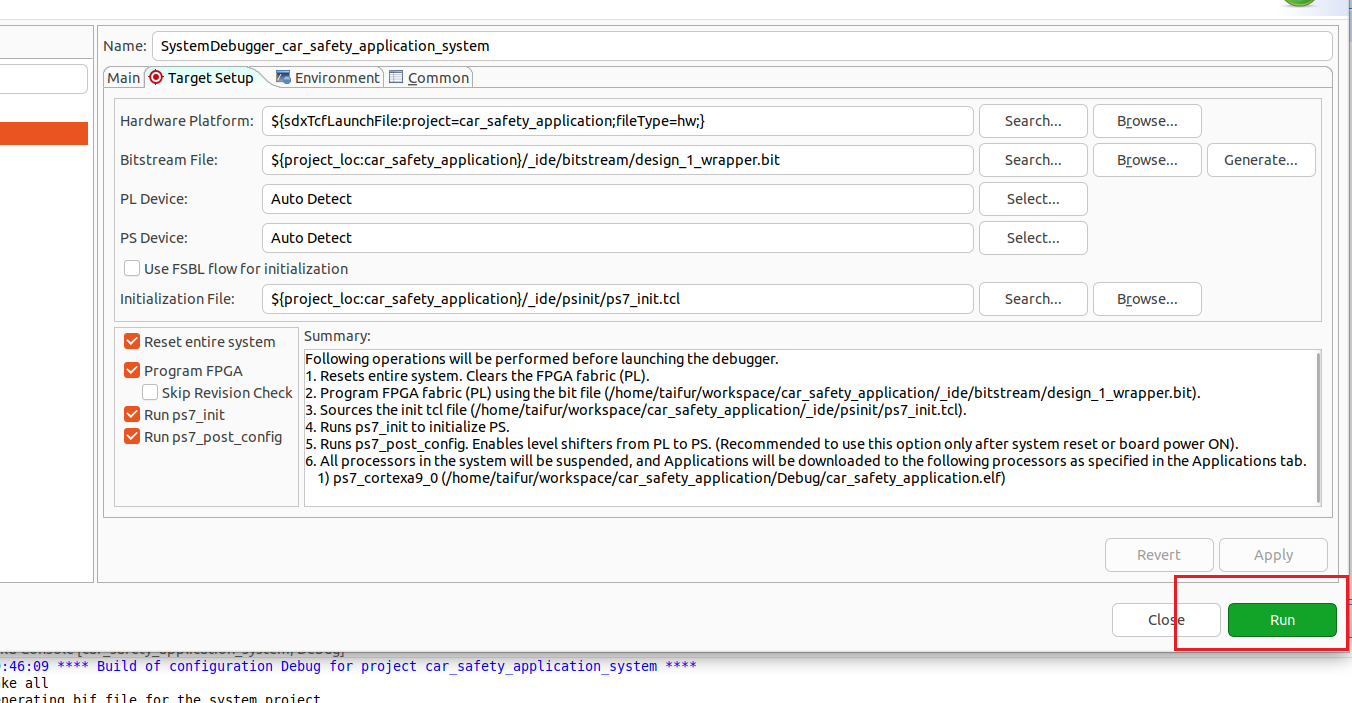
Finally, click on Run. It will run the application on the target device. The current program will print some messages through the serial port. We need to connect any serial terminal software with the device through serial port to watch the messages.
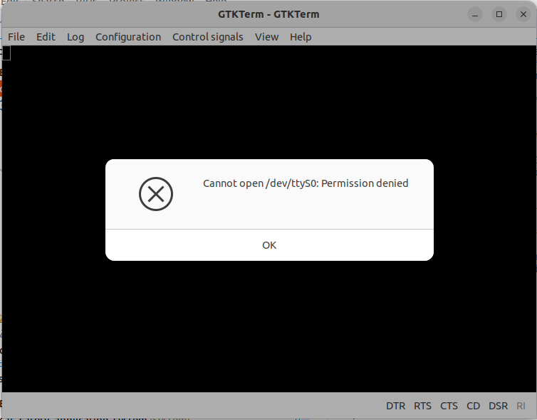
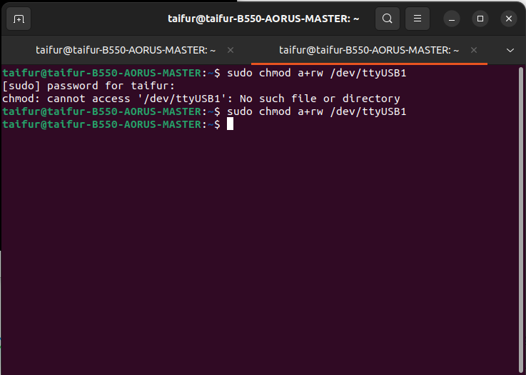
To observe the output you need a serial monitor software. In my Ubuntu, I am using GTKTerm. You may get the permission error when running the GTKTerm for the first time. I got the following warning.
I solved the issue by running the following command from the terminal.
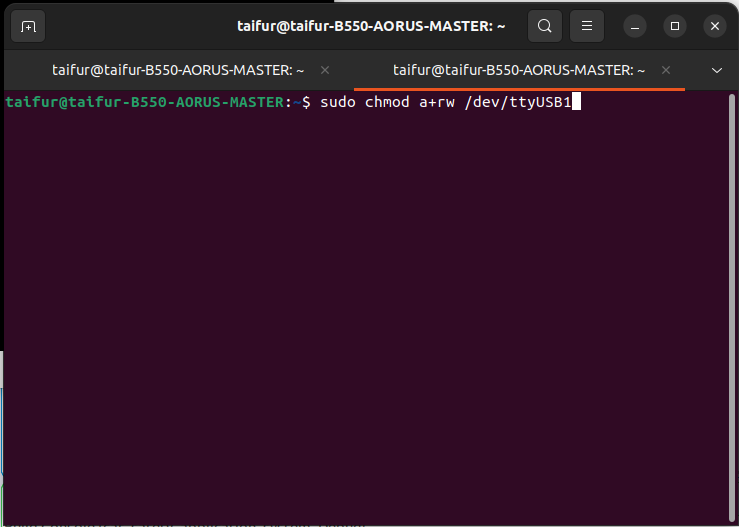
It may ask for the password of your Linux machine. After providing the password I was able to successfully connect the USB with the GTKTerm.
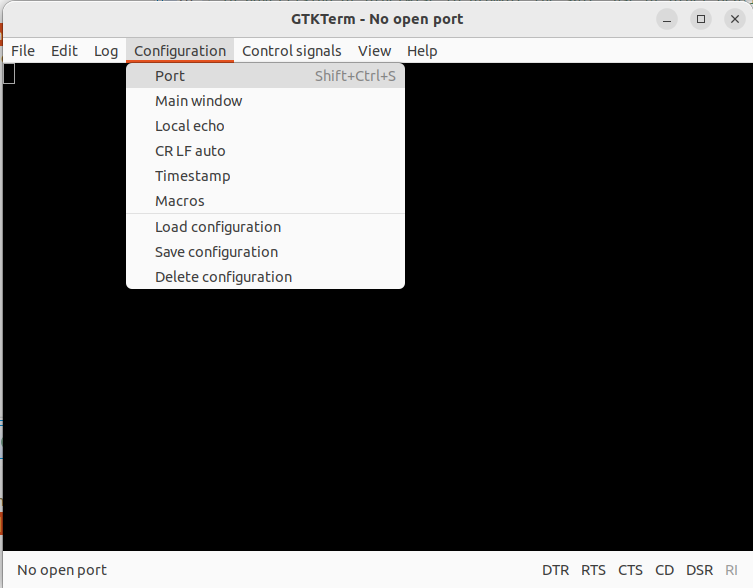
After providing the permission you need to open the appropriate port for the device. Go to the Configuration menu from GTKTerminal and select Port.
Choose the right port (USB1 for my case) and click on OK.
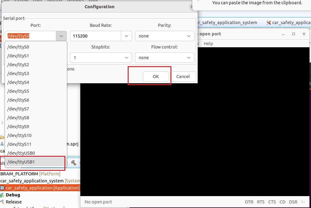
The port will be open like below and you are now ready to receive the data from the selected serial port.

After running the application on the MiniZed board I got the following message on the GTKTerm terminal. Getting the following message means everything is working perfectly so far.

Now I will add my own source file to the application project. For this purpose, I will create a new file under the src directory. I right-clicked on src and choose File from the New submenu.

I am going to add code for interfacing the Grove OLED display with the MiniZed board. To keep the code easy manageable and reusable I will make separate files for every hardware and sensor. First I will make a header file for the OLED display. So, I provided the name for the new file as geove_oled.h with .h extension. The new file will be created and open automatically after clicking on Finish.

I wrote the following code for this grove_oled.h file. I took help from the Arduino library for the oled display provided by SeeedStudio.
#include <stdbool.h>

#define VERTICAL_MODE                       01
#define HORIZONTAL_MODE                     02

#define SeeedGrayOLED_Address               0x3C
#define SeeedGrayOLED_Command_Mode          0x80
#define SeeedGrayOLED_Data_Mode             0x40

#define SeeedGrayOLED_Display_Off_Cmd       0xAE
#define SeeedGrayOLED_Display_On_Cmd        0xAF

#define SeeedGrayOLED_Normal_Display_Cmd    0xA4
#define SeeedGrayOLED_Normal_Display_Cmd_SH1107G    0xA6
#define SeeedGrayOLED_Inverse_Display_Cmd   0xA7
#define SeeedGrayOLED_Activate_Scroll_Cmd   0x2F
#define SeeedGrayOLED_Dectivate_Scroll_Cmd  0x2E
#define SeeedGrayOLED_Set_ContrastLevel_Cmd 0x81

#define Scroll_Left             0x00
#define Scroll_Right            0x01

#define Scroll_2Frames          0x7
#define Scroll_3Frames          0x4
#define Scroll_4Frames          0x5
#define Scroll_5Frames          0x0
#define Scroll_25Frames         0x6
#define Scroll_64Frames         0x1
#define Scroll_128Frames        0x2
#define Scroll_256Frames        0x3

//unsigned char grayH;
//unsigned char grayL;

void init();
void sendCommand(unsigned char command);
void setContrastLevel(unsigned char ContrastLevel) ;
void setHorizontalMode() ;
void setVerticalMode() ;
void setTextXY(unsigned char Row, unsigned char Column) ;
void clearDisplay() ;
void sendData(unsigned char Data);
void setGrayLevel(unsigned char grayLevel);
void putChar(unsigned char C);
void putString(const char* String);
unsigned char putNumber(long long_num);
void drawBitmap(const unsigned char* bitmaparray, int bytes) ;
void setHorizontalScrollProperties(bool direction, unsigned char startRow, unsigned char endRow,
        unsigned char startColumn, unsigned char endColumn, unsigned char scrollSpeed);
void activateScroll();
void deactivateScroll();
void setNormalDisplay();
void setInverseDisplay() ;
Similarly, I have created grove_oled.c file under src directory and added the following code.
#include <stdbool.h>
#include <stdio.h>
#include <unistd.h>
#include "platform.h"
#include "xparameters.h"
#include "xiicps.h"

#include "grove_oled.h"

extern XIicPs Iic;		/**< Instance of the IIC Device */

unsigned char grayH;
unsigned char grayL;

// 8x8 Font ASCII 32 - 127 Implemented
// Users can modify this to support more characters(glyphs)
const unsigned char BasicFont[][8] = {
    {0x00, 0x00, 0x00, 0x00, 0x00, 0x00, 0x00, 0x00},
    {0x00, 0x00, 0x5F, 0x00, 0x00, 0x00, 0x00, 0x00},
    {0x00, 0x00, 0x07, 0x00, 0x07, 0x00, 0x00, 0x00},
    {0x00, 0x14, 0x7F, 0x14, 0x7F, 0x14, 0x00, 0x00},
    {0x00, 0x24, 0x2A, 0x7F, 0x2A, 0x12, 0x00, 0x00},
    {0x00, 0x23, 0x13, 0x08, 0x64, 0x62, 0x00, 0x00},
    {0x00, 0x36, 0x49, 0x55, 0x22, 0x50, 0x00, 0x00},
    {0x00, 0x00, 0x05, 0x03, 0x00, 0x00, 0x00, 0x00},
    {0x00, 0x1C, 0x22, 0x41, 0x00, 0x00, 0x00, 0x00},
    {0x00, 0x41, 0x22, 0x1C, 0x00, 0x00, 0x00, 0x00},
    {0x00, 0x08, 0x2A, 0x1C, 0x2A, 0x08, 0x00, 0x00},
    {0x00, 0x08, 0x08, 0x3E, 0x08, 0x08, 0x00, 0x00},
    {0x00, 0xA0, 0x60, 0x00, 0x00, 0x00, 0x00, 0x00},
    {0x00, 0x08, 0x08, 0x08, 0x08, 0x08, 0x00, 0x00},
    {0x00, 0x60, 0x60, 0x00, 0x00, 0x00, 0x00, 0x00},
    {0x00, 0x20, 0x10, 0x08, 0x04, 0x02, 0x00, 0x00},
    {0x00, 0x3E, 0x51, 0x49, 0x45, 0x3E, 0x00, 0x00},
    {0x00, 0x00, 0x42, 0x7F, 0x40, 0x00, 0x00, 0x00},
    {0x00, 0x62, 0x51, 0x49, 0x49, 0x46, 0x00, 0x00},
    {0x00, 0x22, 0x41, 0x49, 0x49, 0x36, 0x00, 0x00},
    {0x00, 0x18, 0x14, 0x12, 0x7F, 0x10, 0x00, 0x00},
    {0x00, 0x27, 0x45, 0x45, 0x45, 0x39, 0x00, 0x00},
    {0x00, 0x3C, 0x4A, 0x49, 0x49, 0x30, 0x00, 0x00},
    {0x00, 0x01, 0x71, 0x09, 0x05, 0x03, 0x00, 0x00},
    {0x00, 0x36, 0x49, 0x49, 0x49, 0x36, 0x00, 0x00},
    {0x00, 0x06, 0x49, 0x49, 0x29, 0x1E, 0x00, 0x00},
    {0x00, 0x00, 0x36, 0x36, 0x00, 0x00, 0x00, 0x00},
    {0x00, 0x00, 0xAC, 0x6C, 0x00, 0x00, 0x00, 0x00},
    {0x00, 0x08, 0x14, 0x22, 0x41, 0x00, 0x00, 0x00},
    {0x00, 0x14, 0x14, 0x14, 0x14, 0x14, 0x00, 0x00},
    {0x00, 0x41, 0x22, 0x14, 0x08, 0x00, 0x00, 0x00},
    {0x00, 0x02, 0x01, 0x51, 0x09, 0x06, 0x00, 0x00},
    {0x00, 0x32, 0x49, 0x79, 0x41, 0x3E, 0x00, 0x00},
    {0x00, 0x7E, 0x09, 0x09, 0x09, 0x7E, 0x00, 0x00},
    {0x00, 0x7F, 0x49, 0x49, 0x49, 0x36, 0x00, 0x00},
    {0x00, 0x3E, 0x41, 0x41, 0x41, 0x22, 0x00, 0x00},
    {0x00, 0x7F, 0x41, 0x41, 0x22, 0x1C, 0x00, 0x00},
    {0x00, 0x7F, 0x49, 0x49, 0x49, 0x41, 0x00, 0x00},
    {0x00, 0x7F, 0x09, 0x09, 0x09, 0x01, 0x00, 0x00},
    {0x00, 0x3E, 0x41, 0x41, 0x51, 0x72, 0x00, 0x00},
    {0x00, 0x7F, 0x08, 0x08, 0x08, 0x7F, 0x00, 0x00},
    {0x00, 0x41, 0x7F, 0x41, 0x00, 0x00, 0x00, 0x00},
    {0x00, 0x20, 0x40, 0x41, 0x3F, 0x01, 0x00, 0x00},
    {0x00, 0x7F, 0x08, 0x14, 0x22, 0x41, 0x00, 0x00},
    {0x00, 0x7F, 0x40, 0x40, 0x40, 0x40, 0x00, 0x00},
    {0x00, 0x7F, 0x02, 0x0C, 0x02, 0x7F, 0x00, 0x00},
    {0x00, 0x7F, 0x04, 0x08, 0x10, 0x7F, 0x00, 0x00},
    {0x00, 0x3E, 0x41, 0x41, 0x41, 0x3E, 0x00, 0x00},
    {0x00, 0x7F, 0x09, 0x09, 0x09, 0x06, 0x00, 0x00},
    {0x00, 0x3E, 0x41, 0x51, 0x21, 0x5E, 0x00, 0x00},
    {0x00, 0x7F, 0x09, 0x19, 0x29, 0x46, 0x00, 0x00},
    {0x00, 0x26, 0x49, 0x49, 0x49, 0x32, 0x00, 0x00},
    {0x00, 0x01, 0x01, 0x7F, 0x01, 0x01, 0x00, 0x00},
    {0x00, 0x3F, 0x40, 0x40, 0x40, 0x3F, 0x00, 0x00},
    {0x00, 0x1F, 0x20, 0x40, 0x20, 0x1F, 0x00, 0x00},
    {0x00, 0x3F, 0x40, 0x38, 0x40, 0x3F, 0x00, 0x00},
    {0x00, 0x63, 0x14, 0x08, 0x14, 0x63, 0x00, 0x00},
    {0x00, 0x03, 0x04, 0x78, 0x04, 0x03, 0x00, 0x00},
    {0x00, 0x61, 0x51, 0x49, 0x45, 0x43, 0x00, 0x00},
    {0x00, 0x7F, 0x41, 0x41, 0x00, 0x00, 0x00, 0x00},
    {0x00, 0x02, 0x04, 0x08, 0x10, 0x20, 0x00, 0x00},
    {0x00, 0x41, 0x41, 0x7F, 0x00, 0x00, 0x00, 0x00},
    {0x00, 0x04, 0x02, 0x01, 0x02, 0x04, 0x00, 0x00},
    {0x00, 0x80, 0x80, 0x80, 0x80, 0x80, 0x00, 0x00},
    {0x00, 0x01, 0x02, 0x04, 0x00, 0x00, 0x00, 0x00},
    {0x00, 0x20, 0x54, 0x54, 0x54, 0x78, 0x00, 0x00},
    {0x00, 0x7F, 0x48, 0x44, 0x44, 0x38, 0x00, 0x00},
    {0x00, 0x38, 0x44, 0x44, 0x28, 0x00, 0x00, 0x00},
    {0x00, 0x38, 0x44, 0x44, 0x48, 0x7F, 0x00, 0x00},
    {0x00, 0x38, 0x54, 0x54, 0x54, 0x18, 0x00, 0x00},
    {0x00, 0x08, 0x7E, 0x09, 0x02, 0x00, 0x00, 0x00},
    {0x00, 0x18, 0xA4, 0xA4, 0xA4, 0x7C, 0x00, 0x00},
    {0x00, 0x7F, 0x08, 0x04, 0x04, 0x78, 0x00, 0x00},
    {0x00, 0x00, 0x7D, 0x00, 0x00, 0x00, 0x00, 0x00},
    {0x00, 0x80, 0x84, 0x7D, 0x00, 0x00, 0x00, 0x00},
    {0x00, 0x7F, 0x10, 0x28, 0x44, 0x00, 0x00, 0x00},
    {0x00, 0x41, 0x7F, 0x40, 0x00, 0x00, 0x00, 0x00},
    {0x00, 0x7C, 0x04, 0x18, 0x04, 0x78, 0x00, 0x00},
    {0x00, 0x7C, 0x08, 0x04, 0x7C, 0x00, 0x00, 0x00},
    {0x00, 0x38, 0x44, 0x44, 0x38, 0x00, 0x00, 0x00},
    {0x00, 0xFC, 0x24, 0x24, 0x18, 0x00, 0x00, 0x00},
    {0x00, 0x18, 0x24, 0x24, 0xFC, 0x00, 0x00, 0x00},
    {0x00, 0x00, 0x7C, 0x08, 0x04, 0x00, 0x00, 0x00},
    {0x00, 0x48, 0x54, 0x54, 0x24, 0x00, 0x00, 0x00},
    {0x00, 0x04, 0x7F, 0x44, 0x00, 0x00, 0x00, 0x00},
    {0x00, 0x3C, 0x40, 0x40, 0x7C, 0x00, 0x00, 0x00},
    {0x00, 0x1C, 0x20, 0x40, 0x20, 0x1C, 0x00, 0x00},
    {0x00, 0x3C, 0x40, 0x30, 0x40, 0x3C, 0x00, 0x00},
    {0x00, 0x44, 0x28, 0x10, 0x28, 0x44, 0x00, 0x00},
    {0x00, 0x1C, 0xA0, 0xA0, 0x7C, 0x00, 0x00, 0x00},
    {0x00, 0x44, 0x64, 0x54, 0x4C, 0x44, 0x00, 0x00},
    {0x00, 0x08, 0x36, 0x41, 0x00, 0x00, 0x00, 0x00},
    {0x00, 0x00, 0x7F, 0x00, 0x00, 0x00, 0x00, 0x00},
    {0x00, 0x41, 0x36, 0x08, 0x00, 0x00, 0x00, 0x00},
    {0x00, 0x02, 0x01, 0x01, 0x02, 0x01, 0x00, 0x00},
    {0x00, 0x02, 0x05, 0x05, 0x02, 0x00, 0x00, 0x00}
};

void init_groveOLED() {

    sendCommand(0xae);  //Display OFF
    sendCommand(0xd5);  // Set Dclk
    sendCommand(0x50);  // 100Hz
    sendCommand(0x20);  // Set row address
    sendCommand(0x81);  // Set contrast control
    sendCommand(0x80);
    sendCommand(0xa0);  // Segment remap
    sendCommand(0xa4);  // Set Entire Display ON
    sendCommand(0xa6);  // Normal display
    sendCommand(0xad);  // Set external VCC
    sendCommand(0x80);
    sendCommand(0xc0);  // Set Common scan direction
    sendCommand(0xd9);  // Set phase leghth
    sendCommand(0x1f);
    sendCommand(0xdb);  // Set Vcomh voltage
    sendCommand(0x27);
    sendCommand(0xaf);  //Display ON
    sendCommand(0xb0);
    sendCommand(0x00);
    sendCommand(0x11);
}

void sendCommand(unsigned char command) {
	u8 cmd[2] = {0,0};
	int Status;
	cmd[0] = SeeedGrayOLED_Command_Mode;
	cmd[1] = command;
	Status = XIicPs_MasterSendPolled(&Iic, cmd, 2, SeeedGrayOLED_Address);
	if (Status != XST_SUCCESS) {
		//return XST_FAILURE;
	}
		/*
	     * Wait until bus is idle to start another transfer.
		 */
	while (XIicPs_BusIsBusy(&Iic)) {
			/* NOP */
	}

	//return XST_SUCCESS;

}

void setContrastLevel(unsigned char ContrastLevel) {
    sendCommand(SeeedGrayOLED_Set_ContrastLevel_Cmd);
    sendCommand(ContrastLevel);
}

void setHorizontalMode() {
    sendCommand(0xA0);
    sendCommand(0xC8);
}

void setVerticalMode() {
    sendCommand(0xA0);
    sendCommand(0xC0);
}

void setTextXY(unsigned char Row, unsigned char Column) {
    sendCommand(0xb0 + (Row & 0x0F)); // set page/row
    sendCommand(0x10 + ((Column >> 4) & 0x07)); // set column high 3 byte
    sendCommand(Column & 0x0F);  // set column low 4 byte
}

void clearDisplay() {
    unsigned char i, j;

    for (i = 0; i < 16; i++) {
        sendCommand(0xb0 + i);
        sendCommand(0x0);
        sendCommand(0x10);
        for (j = 0; j < 128; j++) {
            sendData(0x00);
        }
    }

}

void sendData(unsigned char Data) {
    u8 cmd[2] = {0,0};
    int Status;
    cmd[0] = SeeedGrayOLED_Data_Mode;
    cmd[1] = Data;
    Status = XIicPs_MasterSendPolled(&Iic, cmd, 2, SeeedGrayOLED_Address);
    if (Status != XST_SUCCESS) {
    	//return XST_FAILURE;
    }
    /*
     * Wait until bus is idle to start another transfer.
    */
    while (XIicPs_BusIsBusy(&Iic)) {
    	/* NOP */
    }

    	//return XST_SUCCESS;
}

void setGrayLevel(unsigned char grayLevel) {
    grayH = (grayLevel << 4) & 0xF0;
    grayL =  grayLevel & 0x0F;
}

void putChar(unsigned char C) {
    if (C < 32 || C > 127) { //Ignore non-printable ASCII characters. This can be modified for multilingual font.
        C = ' '; //Space
    }

    for (int i = 0; i < 8; i++) {
        //read bytes from code memory
        sendData(BasicFont[C - 32][i]); //font array starts at 0, ASCII starts at 32. Hence the translation
    }

}

void putString(const char* String) {
    unsigned char i = 0;
    while (String[i]) {
        putChar(String[i]);
        i++;
    }
}

unsigned char putNumber(long long_num) {
    unsigned char char_buffer[10] = "";
    unsigned char i = 0;
    unsigned char f = 0;

    if (long_num < 0) {
        f = 1;
        putChar('-');
        long_num = -long_num;
    } else if (long_num == 0) {
        f = 1;
        putChar('0');
        return f;
    }

    while (long_num > 0) {
        char_buffer[i++] = long_num % 10;
        long_num /= 10;
    }

    f = f + i;
    for (; i > 0; i--) {
        putChar('0' + char_buffer[i - 1]);
    }
    return f;

}


void drawBitmap(const unsigned char* bitmaparray, int bytes) {

    int Row = 0, column_l = 0x00, column_h = 0x10;

    setHorizontalMode();
    for (int i = 0; i < bytes; i++) {
        sendCommand(0xb0 + Row);
        sendCommand(column_l);
        sendCommand(column_h);

        unsigned char bits = (unsigned char)(bitmaparray[i]);
        unsigned char tmp = 0x00;
        for (int b = 0; b < 8; b++) {
            tmp |= ((bits >> (7 - b)) & 0x01) << b;
        }
        sendData(tmp);
        Row++;
        if (Row >= 16) {
            Row = 0;
            column_l++;
            if (column_l >= 16) {
                column_l = 0x00;
                column_h += 0x01;
            }
        }
    }

}


void setHorizontalScrollProperties(bool direction, unsigned char startRow, unsigned char endRow,
        unsigned char startColumn, unsigned char endColumn, unsigned char scrollSpeed) {
    /*
        Use the following defines for 'direction' :

        Scroll_Left
        Scroll_Right

        Use the following defines for 'scrollSpeed' :

        Scroll_2Frames
        Scroll_3Frames
        Scroll_4Frames
        Scroll_5Frames
        Scroll_25Frames
        Scroll_64Frames
        Scroll_128Frames
        Scroll_256Frames

    */

    if (Scroll_Right == direction) {
        //Scroll Right
        sendCommand(0x27);
    } else {
        //Scroll Left
        sendCommand(0x26);
    }
    sendCommand(0x00);       //Dummmy byte
    sendCommand(startRow);
    sendCommand(scrollSpeed);
    sendCommand(endRow);
    sendCommand(startColumn + 8);
    sendCommand(endColumn + 8);
    sendCommand(0x00);      //Dummmy byte

}

void activateScroll() {
    sendCommand(SeeedGrayOLED_Activate_Scroll_Cmd);
}

void deactivateScroll() {
    sendCommand(SeeedGrayOLED_Dectivate_Scroll_Cmd);
}

void setNormalDisplay() {
    sendCommand(SeeedGrayOLED_Normal_Display_Cmd_SH1107G);
}

void setInverseDisplay() {
    sendCommand(SeeedGrayOLED_Inverse_Display_Cmd);
}


/*
////Example code
init_groveOLED();
clearDisplay();
setNormalDisplay();
setVerticalMode();

//for (char i = 0; i < 16 ; i++) {
    setTextXY(5, 0); //set Cursor to ith line, 0th column
    setGrayLevel(5); //Set Grayscale level. Any number between 0 - 15.
    putString("Hello World OLED"); //Print Hello World

    setTextXY(7, 0); //set Cursor to ith line, 0th column
    setGrayLevel(7); //Set Grayscale level. Any number between 0 - 15.
    putString("Hello MiniZed"); //Print Hello World
  //}

*/

I tested the code on my device by adding the following code on helloworld.c source after adding these two source files to the src directory.
#include <stdio.h>
#include <stdlib.h>
#include "platform.h"
#include "xil_printf.h"
#include "xgpiops.h"
#include "sleep.h"
#include "xil_exception.h"
#include "xparameters.h"
#include "xiicps.h"

#include "multi_gas_sensor.h"
#include "grove_oled.h"
#include "bme280.h"


#define GPIO_DEVICE_ID XPAR_XGPIOPS_0_DEVICE_ID
#define IIC_DEVICE_ID		XPAR_XIICPS_0_DEVICE_ID
#define IIC_SCLK_RATE		400000


XIicPs_Config  *IICConfig;
XIicPs Iic;


void init_iic(){
    IICConfig = XIicPs_LookupConfig(IIC_DEVICE_ID);
    XIicPs_CfgInitialize(&Iic, IICConfig, IICConfig->BaseAddress);
    XIicPs_SetSClk(&Iic, IIC_SCLK_RATE);
}


int main()
{

    init_platform();
    init_iic();

    init_groveOLED();
    clearDisplay();
    setNormalDisplay();
    setVerticalMode();

    setTextXY(0, 0); //set Cursor to ith line, 0th column
    setGrayLevel(5); //Set Grayscale level. Any number between 0 - 15.
    putString("Hello World OLED"); //Print Hello World

    setTextXY(1, 0); //set Cursor to ith line, 0th column
    setGrayLevel(7); //Set Grayscale level. Any number between 0 - 15.
    putString("Hello MiniZed"); //Print Hello World


    while (1)
    {


    }
    cleanup_platform();
    return 0;
}
I was fortunate and the OLED was working as expected.

I developed the following code for the Grove multichannel gas sensor.
The contents of the header file multi_gas_sensor.h is as follows:
#define GAS_SENSOR_I2C_ADDR     0x04

#define ADDR_IS_SET             0           // if this is the first time to run, if 1126, set
#define ADDR_FACTORY_ADC_NH3    2
#define ADDR_FACTORY_ADC_CO     4
#define ADDR_FACTORY_ADC_NO2    6

#define ADDR_USER_ADC_HN3       8
#define ADDR_USER_ADC_CO        10
#define ADDR_USER_ADC_NO2       12
#define ADDR_IF_CALI            14          // IF USER HAD CALI

#define ADDR_I2C_ADDRESS        20

#define CH_VALUE_NH3            1
#define CH_VALUE_CO             2
#define CH_VALUE_NO2            3

#define CMD_ADC_RES0            1           // NH3
#define CMD_ADC_RES1            2           // CO
#define CMD_ADC_RES2            3           // NO2
#define CMD_ADC_RESALL          4           // ALL CHANNEL
#define CMD_CHANGE_I2C          5           // CHANGE I2C
#define CMD_READ_EEPROM         6           // READ EEPROM VALUE, RETURN UNSIGNED INT
#define CMD_SET_R0_ADC          7           // SET R0 ADC VALUE
#define CMD_GET_R0_ADC          8           // GET R0 ADC VALUE
#define CMD_GET_R0_ADC_FACTORY  9           // GET FACTORY R0 ADC VALUE
#define CMD_CONTROL_LED         10
#define CMD_CONTROL_PWR         11

enum {CO, NO2, NH3, C3H8, C4H10, CH4, H2, C2H5OH};

unsigned int get_addr_dta_2(unsigned char addr_reg, unsigned char __dta);
unsigned int get_addr_dta_1(unsigned char addr_reg);
int16_t readData(uint8_t cmd1);
int16_t readR0(void);
int16_t readR(void);
float getR0(unsigned char ch);
float getRs(unsigned char ch);
float measureGas(int gas);
void powerOn(void);
void powerOff(void);
void ledOff(void);
void ledOn(void);
The contents of the source file multi_gas_sensor.c is as follows:
#include <stdbool.h>
#include <stdio.h>
#include <math.h>
#include <unistd.h>
#include "platform.h"
#include "xil_printf.h"
#include "xparameters.h"
#include "xiicps.h"

#include "multi_gas_sensor.h"


extern XIicPs Iic;		/**< Instance of the IIC Device */

int __version;
unsigned int adcValueR0_NH3_Buf;
unsigned int adcValueR0_CO_Buf;
unsigned int adcValueR0_NO2_Buf;
uint16_t res0[3];       //sensors res0
uint16_t res[3];        //sensors res
bool r0_inited;
unsigned char dta_test[20];


unsigned char getVersion() {
    if (get_addr_dta_2(CMD_READ_EEPROM, ADDR_IS_SET) == 1126) {     // get version
        __version = 2;
        printf("Version = 2\n\r");
        return 2;
    }

    __version = 1;
    printf("Version = 1\n\r");
    return 1;
}

unsigned int get_addr_dta_1(unsigned char addr_reg) {

    u8 cmd[1] = {0};
    cmd[0] = addr_reg;
    unsigned char raw[10];

    XIicPs_SetOptions(&Iic,XIICPS_REP_START_OPTION);
    XIicPs_MasterSendPolled(&Iic, cmd, 1, GAS_SENSOR_I2C_ADDR);

    XIicPs_MasterRecvPolled(&Iic, raw, 2, GAS_SENSOR_I2C_ADDR);
    while (XIicPs_BusIsBusy(&Iic)) {
    	/* NOP */
    }
    XIicPs_ClearOptions(&Iic,XIICPS_REP_START_OPTION);

    unsigned int dta = 0;

    dta = raw[0];
    dta <<= 8;
    dta += raw[1];

    switch (addr_reg) {
        case CH_VALUE_NH3:

            if (dta > 0) {
                adcValueR0_NH3_Buf = dta;
            } else {
                dta = adcValueR0_NH3_Buf;
            }

            break;

        case CH_VALUE_CO:

            if (dta > 0) {
                adcValueR0_CO_Buf = dta;
            } else {
                dta = adcValueR0_CO_Buf;
            }

            break;

        case CH_VALUE_NO2:

            if (dta > 0) {
                adcValueR0_NO2_Buf = dta;
            } else {
                dta = adcValueR0_NO2_Buf;
            }

            break;

        default:;
    }
    return dta;
}


unsigned int get_addr_dta_2(unsigned char addr_reg, unsigned char __dta) {

    u8 cmd[2] = {0, 0};
    cmd[0] = addr_reg;
    cmd[1] = __dta;
    unsigned char raw[10];

    XIicPs_SetOptions(&Iic,XIICPS_REP_START_OPTION);
    XIicPs_MasterSendPolled(&Iic, cmd, 2, GAS_SENSOR_I2C_ADDR);

    XIicPs_MasterRecvPolled(&Iic, raw, 2, GAS_SENSOR_I2C_ADDR);
    while (XIicPs_BusIsBusy(&Iic)) {
	/* NOP */
    }
    XIicPs_ClearOptions(&Iic,XIICPS_REP_START_OPTION);

    unsigned int dta = 0;

    dta = raw[0];
    dta <<= 8;
    dta += raw[1];

    return dta;
}


int16_t readData(uint8_t cmd1) {

    uint8_t buffer[4];
    uint8_t checksum = 0;
    int16_t rtnData = 0;

    u8 cmd[1] = {0};
    cmd[0] = cmd1;

    XIicPs_SetOptions(&Iic,XIICPS_REP_START_OPTION);
    XIicPs_MasterSendPolled(&Iic, cmd, 1, GAS_SENSOR_I2C_ADDR);
    usleep(2000);

    XIicPs_MasterRecvPolled(&Iic, buffer, 4, GAS_SENSOR_I2C_ADDR);
    while (XIicPs_BusIsBusy(&Iic)) {
        /* NOP */
    }
    XIicPs_ClearOptions(&Iic,XIICPS_REP_START_OPTION);

    checksum = (uint8_t)(buffer[0] + buffer[1] + buffer[2]);
    if (checksum != buffer[3]) {
        return -4;    //checksum wrong
    }
    rtnData = ((buffer[1] << 8) + buffer[2]);

    return rtnData;//successful
}


int16_t readR0(void) {
    int16_t rtnData = 0;

    rtnData = readData(0x11);

    if (rtnData > 0) {
        res0[0] = rtnData;
    } else {
        return rtnData;    //unsuccessful
    }

    rtnData = readData(0x12);
    if (rtnData > 0) {
        res0[1] = rtnData;
    } else {
        return rtnData;    //unsuccessful
    }

    rtnData = readData(0x13);
    if (rtnData > 0) {
        res0[2] = rtnData;
    } else {
        return rtnData;    //unsuccessful
    }

    return 1;//successful
}

int16_t readR(void) {
    int16_t rtnData = 0;

    rtnData = readData(0x01);
    if (rtnData >= 0) {
        res[0] = rtnData;
    } else {
        return rtnData;    //unsuccessful
    }

    rtnData = readData(0x02);
    if (rtnData >= 0) {
        res[1] = rtnData;
    } else {
        return rtnData;    //unsuccessful
    }

    rtnData = readData(0x03);
    if (rtnData >= 0) {
        res[2] = rtnData;
    } else {
        return rtnData;    //unsuccessful
    }

    return 0;//successful
}


float getR0(unsigned char ch) {       // 0:CH3, 1:CO, 2:NO2
    if (__version == 1) {
        printf("ERROR: getR0() is NOT support by V1 firmware.\n\r");
        return -1;
    }

    int a = 0;
    switch (ch) {
        case 0:         // CH3
            a = get_addr_dta_2(CMD_READ_EEPROM, ADDR_USER_ADC_HN3);
            printf("a_ch3 = ");
            printf("%d\n\r",a);
            break;

        case 1:         // CO
            a = get_addr_dta_2(CMD_READ_EEPROM, ADDR_USER_ADC_CO);
            printf("a_co = ");
            printf("%d\n\r",a);
            break;

        case 2:         // NO2
            a = get_addr_dta_2(CMD_READ_EEPROM, ADDR_USER_ADC_NO2);
            printf("a_no2 = ");
            printf("%d\n\r",a);
            break;

        default:;
    }

    float r = 56.0 * (float)a / (1023.0 - (float)a);
    return r;
}

float getRs(unsigned char ch) {       // 0:CH3, 1:CO, 2:NO2

    if (__version == 1) {
        printf("ERROR: getRs() is NOT support by V1 firmware.\n\r");
        return -1;
    }

    int a = 0;
    switch (ch) {
        case 0:         // NH3
            a = get_addr_dta_1(1);
            break;

        case 1:         // CO
            a = get_addr_dta_1(2);
            break;

        case 2:         // NO2
            a = get_addr_dta_1(3);
            break;

        default:;
    }

    float r = 56.0 * (float)a / (1023.0 - (float)a);
    return r;
}


float measureGAS(int gas) {

    float ratio0, ratio1, ratio2;
    if (1 == __version) {
        if (!r0_inited) {
            if (readR0() >= 0) {
                r0_inited = true;
            } else {
                return -1.0f;
            }
        }

        if (readR() < 0) {
            return -2.0f;
        }

        ratio0 = (float)res[0] / res0[0];
        ratio1 = (float)res[1] / res0[1];
        ratio2 = (float)res[2] / res0[2];
        //printf("%f %f %f", ratio0, ratio1, ratio2);
    } else if (2 == __version) {
        // how to calc ratio/123
        ledOn();
        int A0_0 = get_addr_dta_2(6, ADDR_USER_ADC_HN3);
        int A0_1 = get_addr_dta_2(6, ADDR_USER_ADC_CO);
        int A0_2 = get_addr_dta_2(6, ADDR_USER_ADC_NO2);

        int An_0 = get_addr_dta_1(CH_VALUE_NH3);
        int An_1 = get_addr_dta_1(CH_VALUE_CO);
        int An_2 = get_addr_dta_1(CH_VALUE_NO2);

        ratio0 = (float)An_0 / (float)A0_0 * (1023.0 - A0_0) / (1023.0 - An_0);
        ratio1 = (float)An_1 / (float)A0_1 * (1023.0 - A0_1) / (1023.0 - An_1);
        ratio2 = (float)An_2 / (float)A0_2 * (1023.0 - A0_2) / (1023.0 - An_2);
        //printf("Ratio0 = %f \tRatio1 = %f \tRation2 = %f", ratio0, ratio1, ratio2);
    }

    float c = 0.0;

    switch (gas) {
        case CO: {
            c = pow(ratio1, -1.179) * 4.385; //mod by jack
        	return c;
            break;
            }
        case NO2: {
            c = pow(ratio2, 1.007) / 6.855; //mod by jack
        	return c;
            break;
            }
        case NH3: {
            c = pow(ratio0, -1.67) / 1.47; //modi by jack
        	return c;
            break;
            }
        case C3H8: { //add by jack
            c = pow(ratio0, -2.518) * 570.164;
        	return c;
            break;
            }
        case C4H10: { //add by jack
            c = pow(ratio0, -2.138) * 398.107;
        	return c;
            break;
            }
        case CH4: { //add by jack
            c = pow(ratio1, -4.363) * 630.957;
        	return c;
            break;
            }
        case H2: { //add by jack
            c = pow(ratio1, -1.8) * 0.73;
        	return c;
            break;
            }
        case C2H5OH: { //add by jack
            c = pow(ratio1, -1.552) * 1.622;
        	return c;
            break;
            }
        default:
            break;
    }

    if (2 == __version) {
        ledOff();
    }
    return c;
}

//power on sensor heater
void powerOn(void) {
    if (__version == 1) {
    	u8 cmd[1] = {0};
    	cmd[0] = 0x21;
    	XIicPs_MasterSendPolled(&Iic, cmd, 1, GAS_SENSOR_I2C_ADDR);
    } else if (__version == 2) {
        dta_test[0] = CMD_CONTROL_PWR;
        dta_test[1] = 1;
        XIicPs_MasterSendPolled(&Iic, dta_test, 2, GAS_SENSOR_I2C_ADDR);
    }
}

//power off sensor heater
void powerOff(void) {
    if (__version == 1) {
    	u8 cmd[1] = {0};
    	cmd[0] = 0x20;
    	XIicPs_MasterSendPolled(&Iic, cmd, 1, GAS_SENSOR_I2C_ADDR);
    } else if (__version == 2) {
        dta_test[0] = CMD_CONTROL_PWR;
        dta_test[1] = 0;
        XIicPs_MasterSendPolled(&Iic, dta_test, 2, GAS_SENSOR_I2C_ADDR);
    }
}

void ledOn() {
    dta_test[0] = CMD_CONTROL_LED;
    dta_test[1] = 1;
    XIicPs_MasterSendPolled(&Iic, dta_test, 2, GAS_SENSOR_I2C_ADDR);
}

void ledOff() {
    dta_test[0] = CMD_CONTROL_LED;
    dta_test[1] = 0;
    XIicPs_MasterSendPolled(&Iic, dta_test, 2, GAS_SENSOR_I2C_ADDR);
}


/*
//get raw data
powerOn();
getVersion();

float R0_NH3, R0_CO, R0_NO2;
float Rs_NH3, Rs_CO, Rs_NO2;
float ratio_NH3, ratio_CO, ratio_NO2;

R0_NH3 = getR0(0);
R0_CO  = getR0(1);
R0_NO2 = getR0(2);

Rs_NH3 = getRs(0);
Rs_CO  = getRs(1);
Rs_NO2 = getRs(2);

ratio_NH3 = Rs_NH3 / R0_NH3;
ratio_CO  = Rs_CO / R0_CO;
ratio_NO2 = Rs_NH3 / R0_NO2;

printf("R0_NH3 = %.2f\tR0_CO = %.2f\tR0_NO2 = %.2f\n\r", R0_NH3, R0_CO, R0_NO2);
printf("Rs_NH3 = %.2f\tRs_CO = %.2f\tRs_NO2 = %.2f\n\r", Rs_NH3, Rs_CO, Rs_NO2);

//Measure gas concentration
float c;

c = measureGAS(NH3);
printf("The concentration of NH3 is ");
if (c >= 0) {
   printf("%.2f", c);
   printf(" ppm\n\r");
} else {
   printf("invalid\n\r");
}

c = measureGAS(CO);
printf("The concentration of CO2 is ");
if (c >= 0) {
   printf("%.2f", c);
   printf(" ppm\n\r");
} else {
   printf("invalid\n\r");
}

c = calcGAS(NO2);
printf("The concentration of NO2 is ");
if (c >= 0) {
   printf("%.2f", c);
   printf(" ppm\n\r");
} else {
   printf("invalid\n\r");
}

*/
The code for the bme280 temperature and pressure sensor is as follows:
bme280.h
#define BMP280_ADDRESS   0x77

#define BMP280_REG_DIG_T1    0x88
#define BMP280_REG_DIG_T2    0x8A
#define BMP280_REG_DIG_T3    0x8C

#define BMP280_REG_DIG_P1    0x8E
#define BMP280_REG_DIG_P2    0x90
#define BMP280_REG_DIG_P3    0x92
#define BMP280_REG_DIG_P4    0x94
#define BMP280_REG_DIG_P5    0x96
#define BMP280_REG_DIG_P6    0x98
#define BMP280_REG_DIG_P7    0x9A
#define BMP280_REG_DIG_P8    0x9C
#define BMP280_REG_DIG_P9    0x9E

#define BMP280_REG_CHIPID          0xD0
#define BMP280_REG_VERSION         0xD1
#define BMP280_REG_SOFTRESET       0xE0

#define BMP280_REG_CONTROL         0xF4
#define BMP280_REG_CONFIG          0xF5
#define BMP280_REG_PRESSUREDATA    0xF7
#define BMP280_REG_TEMPDATA        0xFA

//uint8_t bmp280Read8(uint8_t reg);
uint16_t bmp280Read16(uint8_t reg);
uint16_t bmp280Read16LE(uint8_t reg);
int16_t bmp280ReadS16(uint8_t reg);
int16_t bmp280ReadS16LE(uint8_t reg);
uint32_t bmp280Read24(uint8_t reg);
void writeRegister(uint8_t reg, uint8_t val);
bool init_bme280();
float getTemperature(void) ;
uint32_t getPressure(void) ;
float calcAltitude_1(float p0, float p1, float t);
float calcAltitude(float p0);
bme280.c
#include <stdbool.h>
#include <stdio.h>
#include <math.h>
#include <unistd.h>
#include "platform.h"
#include "xil_printf.h"
#include "xparameters.h"
#include "xiicps.h"

#include "bme280.h"

extern XIicPs Iic;		/**< Instance of the IIC Device */

uint16_t dig_T1;
int16_t dig_T2;
int16_t dig_T3;
uint16_t dig_P1;
int16_t dig_P2;
int16_t dig_P3;
int16_t dig_P4;
int16_t dig_P5;
int16_t dig_P6;
int16_t dig_P7;
int16_t dig_P8;
int16_t dig_P9;
int32_t t_fine;


uint8_t bmp280Read8(uint8_t reg) {

	u8 cmd[1] = {0};
	cmd[0] = reg;
	u8 data = 0;
	s32 Status;

	while (XIicPs_BusIsBusy(&Iic));

	Status = XIicPs_MasterSendPolled(&Iic, cmd, 1, BMP280_ADDRESS);

	if (Status != XST_SUCCESS) {
		printf("Failure of iic send\n\r");
		return XST_FAILURE;
	}

	while (XIicPs_BusIsBusy(&Iic));

	Status = XIicPs_MasterRecvPolled(&Iic, &data, 1, BMP280_ADDRESS);

	if (Status != XST_SUCCESS) {
		printf("Failure of iic receive\n\r");
		return XST_FAILURE;
    }

	while (XIicPs_BusIsBusy(&Iic));

    return data;
}

uint16_t bmp280Read16(uint8_t reg) {

  uint8_t msb, lsb;
  u8 cmd[1] = {0};
  cmd[0] = reg;
  uint8_t raw[2];

  //XIicPs_SetOptions(&Iic, XIICPS_REP_START_OPTION);
  while (XIicPs_BusIsBusy(&Iic));

  XIicPs_MasterSendPolled(&Iic, cmd, 1, BMP280_ADDRESS);
  while (XIicPs_BusIsBusy(&Iic));

  XIicPs_MasterRecvPolled(&Iic, raw, 2, BMP280_ADDRESS);

  while (XIicPs_BusIsBusy(&Iic));

  //XIicPs_ClearOptions(&Iic, XIICPS_REP_START_OPTION);

  msb = raw[0];
  lsb = raw[1];

  return (uint16_t) msb << 8 | lsb;

}

uint16_t bmp280Read16LE(uint8_t reg) {
  uint16_t data = bmp280Read16(reg);
  return (data >> 8) | (data << 8);
}

int16_t bmp280ReadS16(uint8_t reg) {
  return (int16_t)bmp280Read16(reg);
}

int16_t bmp280ReadS16LE(uint8_t reg) {
  return (int16_t)bmp280Read16LE(reg);
}

uint32_t bmp280Read24(uint8_t reg) {

  uint32_t data;
  u8 cmd[1] = {0};
  cmd[0] = reg;
  uint8_t raw[3] = {0,0,0};

  //XIicPs_SetOptions(&Iic, XIICPS_REP_START_OPTION);
  XIicPs_MasterSendPolled(&Iic, cmd, 1, BMP280_ADDRESS);
  while (XIicPs_BusIsBusy(&Iic));

  XIicPs_MasterRecvPolled(&Iic, raw, 3, BMP280_ADDRESS);

  while (XIicPs_BusIsBusy(&Iic));

  //XIicPs_ClearOptions(&Iic, XIICPS_REP_START_OPTION);

  data = raw[0];
  data <<= 8;
  data |= raw[1];
  data <<= 8;
  data |= raw[2];
  //printf("Raw data = %d", data);
  return data;

}

void writeRegister(uint8_t reg, uint8_t val) {

  u8 cmd[2] = {0, 0};
  cmd[0] = reg;
  cmd[1] = val;

  XIicPs_MasterSendPolled(&Iic, cmd, 2, BMP280_ADDRESS);
  while (XIicPs_BusIsBusy(&Iic));
}

bool init_bme280() {
  uint8_t chip_id = 0;
  uint8_t retry = 0;

  while ((retry++ < 5) && (chip_id != 0x58)) {
    chip_id = bmp280Read8(BMP280_REG_CHIPID);
    printf("Read chip ID: ");
    printf("%d\n\r", chip_id);
    usleep(100000);
  }

  dig_T1 = bmp280Read16LE(BMP280_REG_DIG_T1);
  dig_T2 = bmp280ReadS16LE(BMP280_REG_DIG_T2);
  dig_T3 = bmp280ReadS16LE(BMP280_REG_DIG_T3);
  dig_P1 = bmp280Read16LE(BMP280_REG_DIG_P1);
  dig_P2 = bmp280ReadS16LE(BMP280_REG_DIG_P2);
  dig_P3 = bmp280ReadS16LE(BMP280_REG_DIG_P3);
  dig_P4 = bmp280ReadS16LE(BMP280_REG_DIG_P4);
  dig_P5 = bmp280ReadS16LE(BMP280_REG_DIG_P5);
  dig_P6 = bmp280ReadS16LE(BMP280_REG_DIG_P6);
  dig_P7 = bmp280ReadS16LE(BMP280_REG_DIG_P7);
  dig_P8 = bmp280ReadS16LE(BMP280_REG_DIG_P8);
  dig_P9 = bmp280ReadS16LE(BMP280_REG_DIG_P9);
  writeRegister(BMP280_REG_CONTROL, 0x3F);
  return true;
}

float getTemperature(void) {
  int32_t var1, var2;
  int32_t adc_T = bmp280Read24(BMP280_REG_TEMPDATA);

  adc_T >>= 4;
  var1 = (((adc_T >> 3) - ((int32_t)(dig_T1 << 1))) *
          ((int32_t)dig_T2)) >> 11;
  var2 = (((((adc_T >> 4) - ((int32_t)dig_T1)) *
            ((adc_T >> 4) - ((int32_t)dig_T1))) >> 12) *
          ((int32_t)dig_T3)) >> 14;
  t_fine = var1 + var2;
  float T = (t_fine * 5 + 128) >> 8;
  //printf("Temp = %f\n\r", T/100);
  return T / 100;
}

uint32_t getPressure(void) {
  int64_t var1, var2, p;
  // Call getTemperature to get t_fine
  getTemperature();

  int32_t adc_P = bmp280Read24(BMP280_REG_PRESSUREDATA);
  //printf("Pressure adc= %d\n\r", adc_P);

  adc_P >>= 4;

  var1 = ((int64_t)t_fine) - 128000;
  var2 = var1 * var1 * (int64_t)dig_P6;
  var2 = var2 + ((var1 * (int64_t)dig_P5) << 17);
  var2 = var2 + (((int64_t)dig_P4) << 35);
  var1 = ((var1 * var1 * (int64_t)dig_P3) >> 8) + ((var1 * (int64_t)dig_P2) << 12);
  var1 = (((((int64_t)1) << 47) + var1)) * ((int64_t)dig_P1) >> 33;
  if (var1 == 0) {
    return 0; // avoid exception caused by division by zero
  }

  p = 1048576 - adc_P;
  p = (((p << 31) - var2) * 3125) / var1;
  var1 = (((int64_t)dig_P9) * (p >> 13) * (p >> 13)) >> 25;
  var2 = (((int64_t)dig_P8) * p) >> 19;
  p = ((p + var1 + var2) >> 8) + (((int64_t)dig_P7) << 4);
  //printf("Pressure = %ld\n\t", (long)p/256);
  return (uint32_t)p / 256;
}

float calcAltitude_1(float p0, float p1, float t) {
  float C;
  C = (p0 / p1);
  //C = pow(C, (1 / 5.25588)) - 1.0;
  C = (C * (t + 273.15)) / 0.0065;
  return C;
}

float calcAltitude(float p0) {
  float t = getTemperature();
  float p1 = getPressure();
  return calcAltitude_1(p0, p1, t);
}

//example read
/*
init_bme280();
float temperature = getTemperature();
printf("Temperature = %.2f\n\n", temperature);
uint32_t pressure = getPressure() ;
printf("Atmospheric pressure = %d HPa\n\r", pressure/100);
float altitude = calcAltitude(1020.09); //mean see level 1020.09
printf("Altitude = %.2f m\n\r", altitude);
*/
The final main code (helloworld.c) is as follows. This code uses the sensors for measuring the gases, temperature, and pressure inside the car, displays the measurements on the OLED display, and runs the buzzer alert on any abnormal findings.
#include <stdio.h>
#include <stdlib.h>
#include "platform.h"
#include "xil_printf.h"
#include "xgpiops.h"
#include "sleep.h"
#include "xil_exception.h"
#include "xparameters.h"
#include "xiicps.h"

#include "multi_gas_sensor.h"
#include "grove_oled.h"
#include "bme280.h"


#define GPIO_DEVICE_ID XPAR_XGPIOPS_0_DEVICE_ID
#define IIC_DEVICE_ID		XPAR_XIICPS_0_DEVICE_ID
#define IIC_SCLK_RATE		400000


XGpioPs Gpio;
XGpioPs_Config *ConfigPtr;

XIicPs_Config  *IICConfig;
XIicPs Iic;

void warning_bell();
void read_and_display_bme280();
void read_and_display_gas();

void init_iic(){
    IICConfig = XIicPs_LookupConfig(IIC_DEVICE_ID);
    XIicPs_CfgInitialize(&Iic, IICConfig, IICConfig->BaseAddress);
    XIicPs_SetSClk(&Iic, IIC_SCLK_RATE);
}

void init_gpio(){
	ConfigPtr = XGpioPs_LookupConfig(GPIO_DEVICE_ID);
	XGpioPs_CfgInitialize(&Gpio, ConfigPtr, ConfigPtr->BaseAddr);
	XGpioPs_SetDirectionPin(&Gpio, 54, 1);
    XGpioPs_SetOutputEnablePin(&Gpio, 54, 1);
}

float temperature, altitude;
uint32_t pressure;

float co, no2, nh3, c3h8, c4h10, ch4, h2, c2h5oh;

int main()
{

    init_platform();
    init_iic();
    init_gpio();

    init_bme280();

    init_groveOLED();
    clearDisplay();
    setNormalDisplay();
    setVerticalMode();

    setTextXY(0, 0); //set Cursor to ith line, 0th column
    setGrayLevel(1); //Set Grayscale level. Any number between 0 - 15.
    putString("CarSafety Device"); //Print Hello World

    setTextXY(0, 0); //set Cursor to ith line, 0th column
    setGrayLevel(2); //Set Grayscale level. Any number between 0 - 15.
    putString("Measured Values:"); //Print Hello World

    //warning_bell();

    while (1)
    {

    	read_and_display_bme280();
    	usleep(1000000);
    	read_and_display_gas();
    	usleep(1000000);

    	if(temperature>35 || pressure>1200 || co>100 || nh3>2 || ch4>5100000){
    		warning_bell();
    	}

    }
    cleanup_platform();
    return 0;
}

void warning_bell(){
	XGpioPs_WritePin(&Gpio, 54, 0x1);
	usleep(500000);
	XGpioPs_WritePin(&Gpio, 54, 0x0);
	usleep(500000);
	XGpioPs_WritePin(&Gpio, 54, 0x1);
	usleep(500000);
	XGpioPs_WritePin(&Gpio, 54, 0x0);
	usleep(500000);
	XGpioPs_WritePin(&Gpio, 54, 0x1);
	usleep(500000);
	XGpioPs_WritePin(&Gpio, 54, 0x0);
}

void read_and_display_bme280(){
	//init_bme280();
	usleep(100000);
	temperature = getTemperature();
	printf("Temperature = %.2f C\n\r", temperature);
	usleep(100000);

	pressure = getPressure();
	printf("Atmospheric pressure = %d HPa\n\r", pressure/100);
	usleep(100000);

	altitude = calcAltitude(1020.09); //mean see level 1020.09
	printf("Altitude = %.2f m\n\r", altitude);

	//convert float value to string for showing in oled display.
	int tempInt1 = temperature;
	float tempF = temperature - tempInt1;
	int tempInt2 = tempF * 100;

	char temperature_string[30];
	snprintf(temperature_string, sizeof(temperature_string), "Temp. = %d.%d C", tempInt1, tempInt2);

	int presInt1 = pressure/100;

	char pressure_string[30];
	snprintf(pressure_string, sizeof(pressure_string), "Pres. = %d HPa", presInt1);

	int altiInt1 = altitude;
	float altiF = altitude - altiInt1;
	int altiInt2 = altiF * 100;

	char altitude_string[30];
	snprintf(altitude_string, sizeof(altitude_string), "Alti. = %d.%d m", altiInt1, altiInt2);

	setTextXY(3, 0); //set Cursor to ith line, 0th column
	putString(temperature_string);

    setTextXY(4, 0);
	putString(pressure_string);

	setTextXY(5, 0);
	putString(altitude_string);
}

void read_and_display_gas(){
	powerOn();
	getVersion();

	co = measureGAS(CO);
    printf("The concentration of CO is %.2f ppm\n\r", co);

	no2 = measureGAS(NO2);
	printf("The concentration of NO2 is %.2f ppm\n\r", no2);

	nh3 = measureGAS(NH3);
	printf("The concentration of NH3 is %.2f ppm\n\r", nh3);

	c3h8 = measureGAS(C3H8);
	printf("The concentration of C3H8 is %.2f ppm\n\r", c3h8);

	c4h10 = measureGAS(C4H10);
	printf("The concentration of C4H10 is %.2f ppm\n\r", c4h10);

	ch4 = measureGAS(CH4);
	printf("The concentration of CH4 is %.2f ppm\n\r", ch4);

	h2 = measureGAS(H2);
	printf("The concentration of H2 is %.2f ppm\n\r", h2);

	c2h5oh = measureGAS(C2H5OH);
	printf("The concentration of C2H5OH is %.2f ppm\n\r", c2h5oh);

	powerOff();

	int co1 = co;
    float cof = co - co1;
    int co2 = cof * 100;
    char co_string[20];
    snprintf(co_string, sizeof(co_string), "CO = %d.%d", co1, co2);

    int no21 = no2;
    float no2f = no2 - no21;
    int no22 = no2f * 100;
    char no2_string[20];
    snprintf(no2_string, sizeof(no2_string), "NO = %d.%d", no21, no22);

    int nh31 = nh3;
    float nh3f = nh3 - nh31;
    int nh32 = nh3f * 100;
    char nh3_string[20];
    snprintf(nh3_string, sizeof(nh3_string), "NH3 = %d.%d", nh31, nh32);

    int c3h81 = c3h8;
    float c3h8f = c3h8 - c3h81;
    int c3h82 = c3h8f * 100;
    char c3h8_string[20];
    snprintf(c3h8_string, sizeof(c3h8_string), "C3H8 = %d.%d", c3h81, c3h82);

    int c4h101 = c4h10;
    float c4h10f = c4h10 - c4h101;
    int c4h102 = c4h10f * 100;
    char c4h10_string[20];
    snprintf(c4h10_string, sizeof(c4h10_string), "C4H10 = %d.%d", c4h101, c4h102);

    int ch41 = ch4;
    float ch4f = ch4 - ch41;
    int ch42 = ch4f * 100;
    char ch4_string[20];
    snprintf(ch4_string, sizeof(ch4_string), "CH4 = %d.%d", ch41, ch42);

    int h21 = h2;
    float h2f = h2 - h21;
    int h22 = h2f * 100;
    char h2_string[20];
    snprintf(h2_string, sizeof(h2_string), "H2 = %d.%d", h21, h22);

    int c2h5oh1 = c2h5oh;
    float c2h5ohf = c2h5oh - c2h5oh1;
    int c2h5oh2 = c2h5ohf * 100;
    char c2h5oh_string[20];
    snprintf(c2h5oh_string, sizeof(c2h5oh_string), "C2H5OH = %d.%d", c2h5oh1, c2h5oh2);

    setTextXY(7, 0);
    putString(co_string);
    setTextXY(8, 0);
    putString(no2_string);
    setTextXY(9, 0);
    putString(nh3_string);
    setTextXY(10, 0);
    putString(c3h8_string);
    setTextXY(11, 0);
    putString(c4h10_string);
    setTextXY(12, 0);
    putString(ch4_string);
    setTextXY(13, 0);
    putString(h2_string);
    setTextXY(14, 0);
    putString(c2h5oh_string);
    setTextXY(15, 0);
    putString("All units ppm");
}
Running the Final Code
After developing the final code, it was run in the MiniZed board with all the sensors, display, and buzzer connected. The device is working perfectly.

The display is showing all the measurements. The gas parameters are shown in ppm.

Demo Video
I prepared a very short video demonstration for my project. To show the alert functionality I used a soldering Iron. When a heated soldering iron is brought very close to the BME280 sensor the temperature goes abnormally high and runs the buzzer alert.
Full Design Source
The full source both hardware and software design are available in the following GitHub link. You are free to download and modify the code according to your requirements. I tried to keep the source code as clean as possible so that anyone could reuse the code.
GitHub link of all the source files: https://github.com/taifur20/CarSafety_FPGA_Project


