


Introduction
In this blog post I want to touch a more operational topic related to working with AMD FPGAs. I have been working with AMD FPGAs for some time and this blog post is inspired by an issue I have faced several times in the past
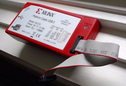
When debugging and updating AMD FPGA designs, usually you would need to have a JTAG cable attached. This can either be a Xilinx platform cable
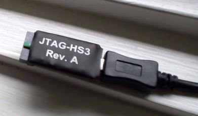
or a compatible 3rd party tool such as the Digilent HSIII cable
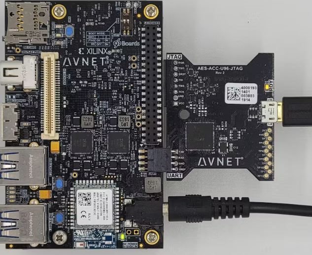
or perhaps the development board comes with a USB-JTAG interface built on to the board itself, or available as an add-on (as in case of the Ultra96-v2)
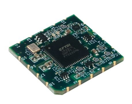
or if you built a custom board, you can also use one of the USB-JTAG interface modules from Digilent added to your board. The castellated holes allow easy integration.
In all cases, you need a physical cable connected to your board. For development/testing on the desk, it is fine. However sometimes it's not the ideal solution for situations like
- When you have your FPGA board mounted on a mobile platform (e.g., a camera gimbal)
- When you have your FPGA board inside an enclosure
- For field deployed systems, where you want the ability to debug if/when needed, without exposing a full JTAG header out to the device chassis.
Cost is another factor since either of the above solutions will set you back some $$. Not so bad for a development system, but the costs can add up in deployment.
Based on some past experience with projects, I wanted to explore some new options for my upcoming project. For this particular project, the FPGA will be mounted on a motorized gimbal, so having a cable going to it from the development machine all the time will not be very suitable.
Xilinx Virtual Cable (XVC)
AMD (previously Xilinx) has made available something called XVC (Xilinx Virtual Cable) for some time, which allows another embedded processor/controller to act as the device facilitating a JTAG connection between the FPGA and host machine. However, implementing the XVC code for your own controller required some work. Recently, I have come across some open source projects whereby some smart people have ported the XVC code to some of the popular microcontrollers. Most notable are the ports to ESP-32 and RPi Pico (RP2040). Both open up exciting possibilities. I have looked at both of them and have (so far) concluded the following:
- XVC - ESP32 : Provides JTAG over a WIFI connection
- XVC - RP2040: Provides JTAG over a USB interface
You might be thinking, what's the advantage of the RP2040 port of the XVC, since the official solutions mentioned before already provide USB over JTAG. Well, one main advantage is cost, since RP2040 is a very cost effective controller. Secondly, in many designs you need a low power system controller that takes care of basic IO functions, especially when the main FPGA is now powered up. A controller such as the RP2040 is a good candidate for such. If it can also act as the JTAG cable, then we only need one interface out of the system, i.e., a USB connection to the RP2040 which can update not just the RP2040 software but also help debug and update the FPGA code.
For my application, I need a wireless JTAG interface, so I am going to look at the ESP32 port in this post.
Preparing our XVC-ESP32 probe
First , I went to the XVC-ESP32 github project (https://github.com/kholia/xvc-esp32 ) to download the source code files. The two files that I was mainly interested in were:
- xvc-esp32.ino -> All the XVC implementation code is in this file
- credentials.h -> Only contains the Wifi SSID and password to connect to your network.
First, I installed Arduino IDE from the official arduino page. (https://www.arduino.cc/en/software ) and then installed the ESP32 boards into it. There are plenty of tutorials of doing this on the internet so I will not go into the details here.
Once installed, I created a new sketch and copied the two files above into the sketch. Then I selected the respective ESP32 board (in my case "DOIT ESP32 DEVKIT V1") and set the code to compile. It compiled without errors. After this, I changed the credentials.h file to reflect the SSID and password for my home wifi, and then I clicked "verify" again to compile with the updated wifi credentials.
Hardware connections
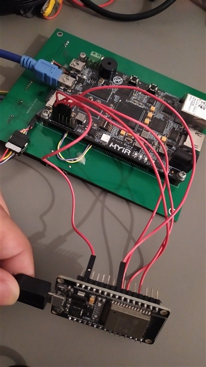
At this point I needed to make the hardware connections between the ESP32 board and the AMD FPGA board. I was originally planning to use the Ultra96v2, however, I found out that the JTAG headers have less than 2.54mm spacing, so while I source the appropriated connector, I decided to use another Zynq 7020 based board from AMD's partner company MYIR, which I already have from another project. The board is called the Zturn board, and the good thing about this board is that the JTAG pins have 2.54mm spacing, which matches perfectly with my DuPont jumper wires.
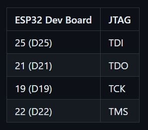
The XVC-ESP32 project's readme gives the default wiring pinout, which I did not change:
And this is the pinout of the JTAG connector on my Zturn-7020 board:
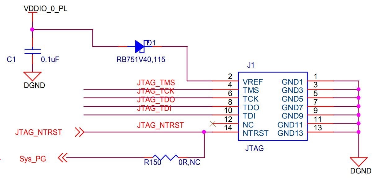
Since both the boards will get their own power, all I needed to do was connect GND, TMS, TCK, TDO, TDI (5 wires in total).
However, I got a bit confused with the TDI/TDO connections. Normally TDO is the "data out" while TDI is the "data In" for JTAG and I was wondering whether I need to do a cross-over connection, or if the signals in the XVC-ESP32 refer to the what pins they should be connected to on the FPGA side. I felt it was important to sort this out before making connections because the JTAG TDO signals are push-pull signals (actively driven) and not open drain, so connecting one side's output to the other side's output pin would not do well with our hardware.
Anyway, I looked at the code and saw that the TDI pin was set to output, while the TDO pin was set to input in the ESP32 code.
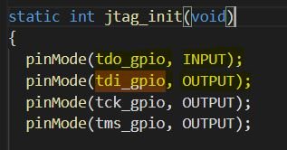
This confirmed that the TDI and TDO pins in XVC-ESP32 actually refer to the pins on FPGA JTAG that they will connect to. Once this was clear, I made the connections using 5 commonly available DuPont jumper wires.

Once this was done, I uploaded the XVC-ESP32 code to my ESP32 board, and then powered on both boards.
When running the XVC-ESP32 code, the board connects to the SSID using the credentials given in the credentials.h file. I used the "Fing" app on my smartphone to scan the home wireless network and found the ESP32 in the list of connected devices. This also gave me the IP address of the ESP32.
Testing with Vivado
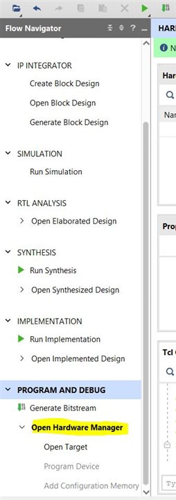
Now, to test with Vivado, I opened an existing design I had previously created for that board. After the design had opened, since it already had the bitstream generated, I directly opened the "Hardware Manager" under "Program and Debug"
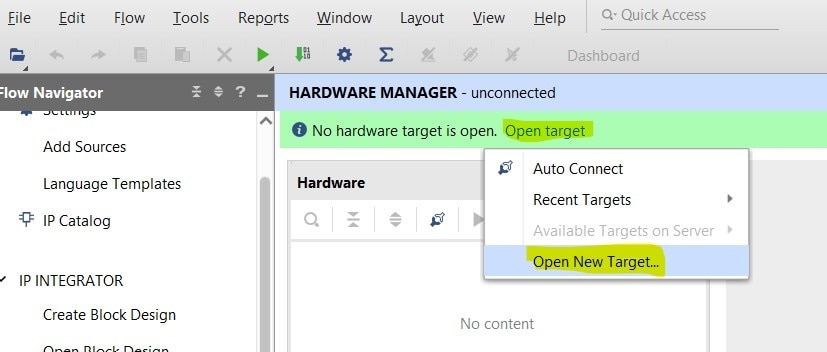
This opened the hardware manager window. To connect to the target board, I needed to tell Vivado where the "virtual cable" was located. I clicked "Open Target" -> "Open new Target"
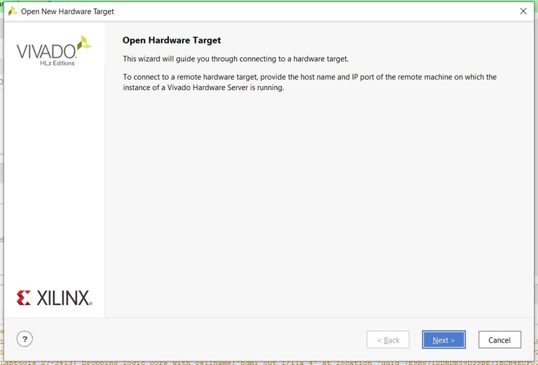
The "Open new hardware" wizard opened. Press next on the first page
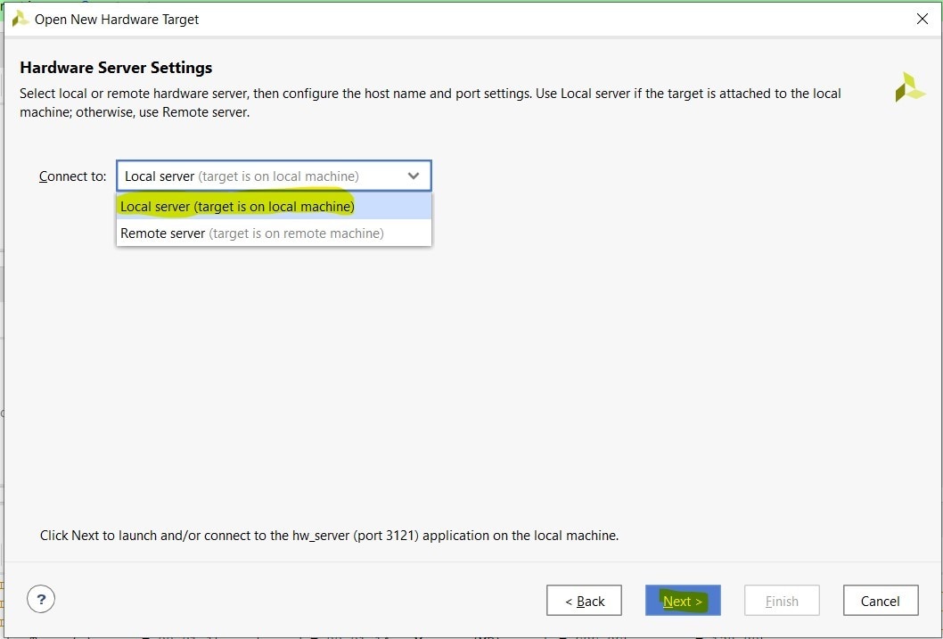
The next one might feel a bit counter-intuitive. We might think we need to specify "remote server" since the XVC-ESP32 is not connected to our machine, but actually this is referring to the "hw_server" process that actually runs on our own machine, and does the work of connecting to the remote target in this case.
So select "local server" and hit "Next"
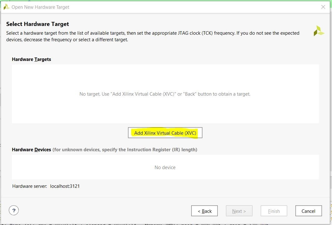
On the next page, click "Add Xilinx Virtual Cable(XVC)".
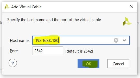
This opens a new dialog box. Here I use the IP address of the XVC-ESP32 which I obtained from the network using the "Fing" app. I did not change the default port and clicked OK.
Now I could see that the XVC interface was detected by Vivado.
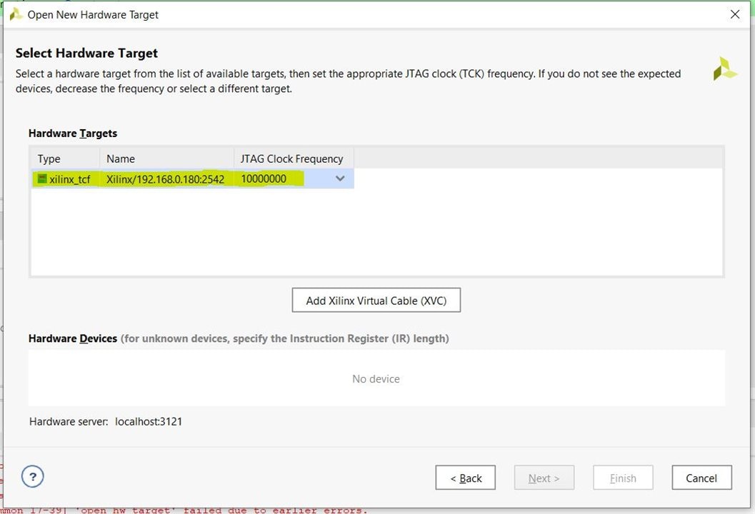
however, for some reason it did not detect any device. The solution to this, I found was to just click "Back" and then "Next" again to come back to this page. Now the Zynq 7020 FPGA was seen as detected.
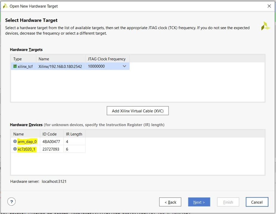
Click "next" and then "Finish" on the summary page.
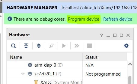
Vivado took a minute to establish connection. It then showed the connected device status. I clicked "program device" to initiate configuring the FPGA.
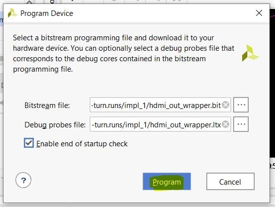
On the dialog box that appeared, Vivado automatically picked the correct files to send to the FPGA, so I clicked "program" to proceed.
The .bit file was 3951KB in size and it took 70 seconds to program the device, so the actual throughput/programming speed I got was around 57KB/s. This is a bit slower than if you do this via a USB-JTAG cable but its still very usable.
Once the process completed, I could open a Debug core. In this particular design I did not have an ILA included so as a test I just opened the XADC to log the chip temperature, which was working flawlessly.
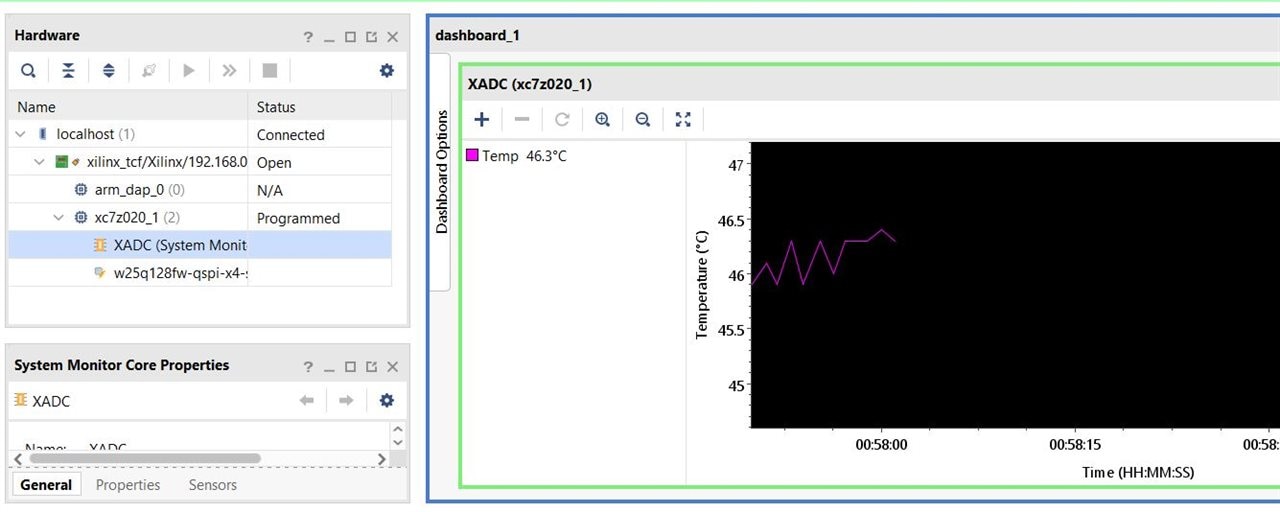
The experiment is a success!!
Now that we can see that we can connect to the remote FPGA through the XVC-ESP32 debug probe, we can even debug the design via VITIS, or program the flash on the board remotely. This opens up new possibilities for my upcoming project and I am very excited about it!
My special thanks to the smart people who worked on this and made it available for all of us to use in our projects!. Please consider visiting the github pages and "Star"-ing the repositories to show your love for these amazing projects
https://github.com/kholia/xvc-esp32
https://github.com/kholia/xvc-pico
Thanks for reading and ..see you in the next blog post!
Top Comments