


Table of Contents
Objectives
As my Blog #2 said, the MiniZed is a single ARM Cortex®-A9 processor APU FPGA device. That means I am able to build an embedded OS, such as AMD Petalinux on MiniZed. The blog will demonstrate how to build AMD Petalinux for Lab 7 and boot the Petalinux through JTAG chain. The main reason I did not plan to erase the image on QSPI memory is to keep a golden image on MiniZed for the WiFi Linux APIs in my future homework.
Build BRAM + PWM IP Vivado Project
There is a gap between the source code from Avnet MiniZed TTC training materials, bram_test.c and Vivado FPGA project as I mentioned in my Blog 2. I presented how to update the software to get BRAM-to-BRAM testing case up into running. In fact, a better solution to close the gap is presented below.

Fig1: BRAM Memory Configuration for BRAM_test.c
Avnet MiniZed TTC lecture and Lab 7 instruction are able to lead any student to build the Vivado project very smoothly. Fig 1 setting can get BRAM-to-BRAM test case: bram_test.c from Avent training source codes, up into running without any issues. The largest memory block moving, Sending 8192Byte data, is tested as Fig 2.

Fig 2. BRAM-to-BRAM Data Transfer: 8192 Bytes
Why do I need the memory range of the BRAM controller to be as big as 64KB as Fig 1 presented? Here is the theory under the hood.
AXI bus is a type of 64-Bit width bus, however the C source codes defined the data moving package is 32-bit as this:
source = (u32 *) BRAM_MEMORY;
destination = (u32 *) (BRAM_MEMORY + LENGTH);  // LENGTH = 8196
8192B *32bit/8bit = 4*8KB=32KB. BRAM_test.c can move 32KB data from BRAM in one direction and need another 32KB space to receive the data packages. That means it needs twice of 32KB memory at BRAM. 64KB becomes the memory range for BRAM setting for Lab 6/7.
I uploaded the Vivado project output(xsa file) in Github (ref[2]).
Lab 7 is a good training material for learning Vivado IP flow. I am not going to repeat the details on how to create an IP repo and integrate it into a Vivado project in the blog. I plan to discuss how I build Petalinux from the Lab 7 Vivado project as below.
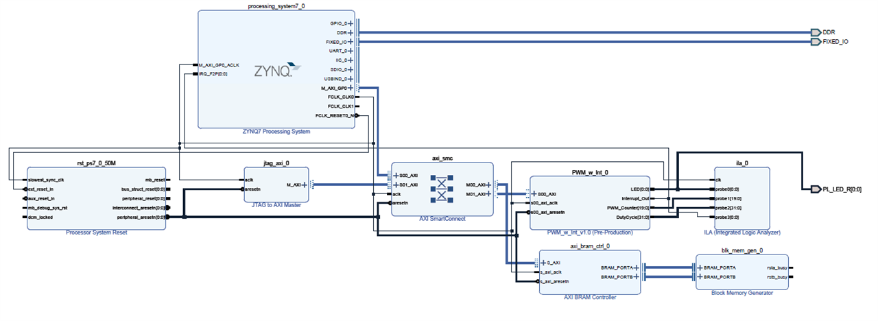
Fig 3. Lab 7 Vivado Project Block Design View
Petalinux Project For Lab 7
I plan to boot Petalinux from JTAG chain without using QSPI flash for the lab7/8/9. So a local Petalinux project is a must for the tasks. The way I build a Petalinux is simple. AMD UG 1144 (ref[1])is my guidance for the homework.
Step 01: Create Petalinux project
petalinux-create --force --type project --template zynq --name MiniZed_BRAM

Fig 4. Petalinux Command demo: petalinux-create
Notes: ug1144(Chapter 3), petalinux-create command is used to create a new Petalinux project.
--template zynq : I select zynq platform for MiniZed project. There are five platforms from Petalinux 2021.1: versal, zynqMP, zynq, microblaze.
Step 02: Get into Petalinux project folder
cd MiniZed_BRAM

Fig 5. Petalinux command demo: get into Petalinux project folder
Step 03: Configure Vivado/Petalinux hardware
petalinux-config --get-hw-description=../

Fig 6. Petalinux command demo: petalinux-config
I import the hardware description with petalinux-config command by giving the path of the directory containing the .xsa file.
Then Petalinux tool will pop up configuration GUI as below.
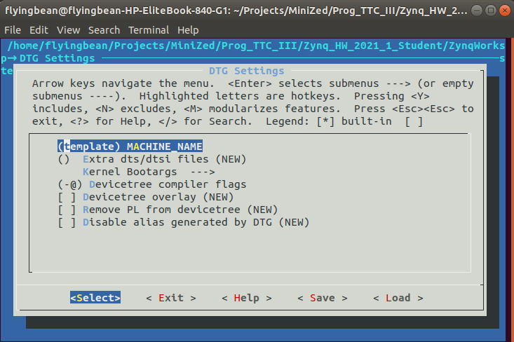
Fig 7. Petalinux command demo: Petalinux configuration GUI
I do not change any configuration at the initial Petalinux running. I also leave (template) MACHIN_NAME without choosing any Xilinx evaluation board/BSP name, since there is no MINIZED BSP from the Petalinux tool chain for now.
Step 04: Build Petalinux Images
I kick off the final Petalinux command:
petalinux-build

Fig 8. Petalinux command demo: petalinux-build
After 2-3 hours building time, there are some errors print out from Ubuntu.

Fig 9. MiniZed Lab 7 Petalinux Initial Build Errors
The red error messages are very overwhelming. After I review the error messages, there is only one error matter to the build, which is marked in yellow as Fig 10.

Fig 10. Petalinux Build Error Message Trouble-shooting
Error message: /axi/ptm@f889d000: reference to non-existent node or label “cpu1”.
MiniZed is a single core FPGA system. There is no second cpu (cpu1) on FPGA. So the default device tree generated from Petalinux needs some manual workarounds as below.

Fig 11. Petalinux Build Device Tree Update: system-user.dtsi
Element14 Community already had some discussion on this topic./technologies/fpga-group/f/forum/39566/petalinux-2020-1-for-single-core-zynq-soc_variant
Root case:
Please check device tree file zynq-7000.dtsi from 2021.1 as below. It looks debug_cpu_pt entry was added with 2021.1 version as default for both CPUs.
ptm@f889c000 {

compatible = "arm,coresight-etm3x", "arm,primecell";

reg = <0xf889c000 0x1000>;

clocks = <&clkc 27>, <&clkc 46>, <&clkc 47>;

clock-names = "apb_pclk", "dbg_trc", "dbg_apb";

cpu = <&cpu0>;

out-ports {

port {

ptm0_out_port: endpoint {

remote-endpoint = <&funnel0_in_port0>;

};

};

};

};


ptm@f889d000 {

compatible = "arm,coresight-etm3x", "arm,primecell";

reg = <0xf889d000 0x1000>;

clocks = <&clkc 27>, <&clkc 46>, <&clkc 47>;

clock-names = "apb_pclk", "dbg_trc", "dbg_apb";

cpu = <&cpu1>;

out-ports {

port {

ptm1_out_port: endpoint {

remote-endpoint = <&funnel0_in_port1>;

};

};

};

};
I think the permanent solution should be
ptm@f889c000 {

compatible = "arm,coresight-etm3x", "arm,primecell";

reg = <0xf889c000 0x1000>;

clocks = <&clkc 27>, <&clkc 46>, <&clkc 47>;

clock-names = "apb_pclk", "dbg_trc", "dbg_apb";

cpu = <&cpu0>;

out-ports {

port {

ptm0_out_port: endpoint {

remote-endpoint = <&funnel0_in_port0>;

};

};

};

};


//ptm@f889d000 {

//compatible = "arm,coresight-etm3x", "arm,primecell";

//reg = <0xf889d000 0x1000>;

////clocks = <&clkc 27>, <&clkc 46>, <&clkc 47>;

clock-names = "apb_pclk", "dbg_trc", "dbg_apb";

//cpu = <&cpu1>;

//out-ports //{

//port {

//ptm1_out_port: endpoint {

//remote-endpoint = <&funnel0_in_port1>;

//};

//};

//};

//};
Update system_user.dtsi as Fig 11 and rerun petalinux-build command line as Fig 8.
The working Petalinux images can be found at ref[2].
Boot Petalinux from JTAG
I finally found myself a good excuse to boot Petalinux image from JTAG since MiniZed has no SD card port. UG1144(ref[1]) chapter 5 gives all details on this feature.
Step 01: Power off the board and connect the JTAG port on MiniZed via USB cable to the Ubuntu host PC.
Step 02: Booting mode of MiniZed has to be JTAG mode as Fig 12, SW1 has a mark, J, beside the part, which means JTAG booting mode.

Fig 12. Boot Mode Setting on MiniZed
Step 03: Testing and check JTAG port name from XSCT
Vitis XSCT utility can detect JTAG url number as Fig 13.

Fig 13. MiniZed JTAG Port url Number
Step 04: Package pre-built folder under Petalinux project
petalinux-package --prebuilt

Fig 14. Petalinux command demo: petalinux-package
Step 05: Boot Petalinux via JTAG
Petalinux-boot –jtag -prebuild 3 –hw_server-url TCP:127.0.0.1:3121

Fig 15. Petalinux command demo: petalinux-boot
I finally boot Petalinux from JTAG and I can communicate with MiniZed via UART on Petalinux OS. Great start point for Petalinux API development.

Fig 16. Petalinux of Lab 7 from UART
In summary, JTAG booting Petalinux image will give me a lot of freedom to develop Petalinux API projects on MiniZed platform before I get a beta version of the Petalinux images to be programmed into either eMMC flash memory or QSPI flash memory.
References
[1] UG1144, Petalinux Tools Documentation Reference Guid, V2021.1, 2021
[2] Flyingbean MiniZed Github link: https://github.com/flyingbean/MiniZed.git

